Table of Contents
Advertisement
Advertisement
Table of Contents
Troubleshooting

Related Manuals for Fluke Hart Scientific 1522


Summary of Contents for Fluke Hart Scientific 1522
- Page 1 Hart Scientific 1522 Handheld Thermometer Readout User’s Guide Rev. 5B2202...
- Page 2 Fluke Corporation, Hart Scientific Division 799 E. Utah Valley Drive • American Fork, UT 84003-9775 • USA Phone: +1.801.763.1600 • Telefax: +1.801.763.1010 E-mail: support@hartscientific.com www.hartscientific.com Subject to change without notice. • Copyright © 2005 • Printed in USA Rev. 5B2202...
-
Page 3: Table Of Contents
Unpacking ......13 Use Proper Care with the 1522 and Accessories ..13 Learn About the Features and Components . - Page 4 7 Display Functions......31 8 Communications Interface....47 Probe .
- Page 5 8.2.1 Primary Commands ....... 48 8.2.2 Calibration Commands ......50 9 Calibration .
- Page 6 Figures and Tables Table 1 Figure 1 Figure 2 Figure 3 Figure 4 Figure 5 Figure 6 Figure 7 Figure 8 Figure 9 Figure 10 Infrared Dongle Position ......60 International Electrical Symbols .
-
Page 7: Before You Start
Before You Start Symbols Used Table 1 lists the International Electrical Symbols. Some or all of these symbols may be used on the instrument or in this manual. Table 1 International Electrical Symbols Symbol Description AC (Alternating Current) AC-DC Battery CE Complies with European Union Directives Double Insulated Electric Shock... -
Page 8: Safety Information
1522 Handheld Thermometer Readout User’s Guide Symbol Safety Information Use this instrument only as specified in this manual. Otherwise, the protection provided by the instrument may be impaired. The following definitions apply to the terms “Warning” and “Caution”. “WARNING” identifies conditions and actions that may pose hazards to the user. -
Page 9: Cautions
AC adapter. Refer repairs or replacement components to the manufacturer. The instrument and thermometer probes are sensitive and can be easily damaged. Always handle these devices with care. DO NOT allow them to be dropped, struck, stressed, or overheated. -
Page 10: Authorized Service Centers
1522 Handheld Thermometer Readout User’s Guide Keep the probe wires clean and away from fluids. Authorized Service Centers Please contact one of the following authorized Service Centers to coordinate service on your Hart product: Fluke Corporation, Hart Scientific Division 799 E. Utah Valley Drive American Fork, UT 84003-9775 Phone: +1.801.763.1600... - Page 11 Fluke South East Asia Pte Ltd. Fluke ASEAN Regional Office Service Center 60 Alexandra Terrace #03-16 The Comtech (Lobby D) 118502 SINGAPORE Phone: +65 6799-5588 Telefax: +65 6799-5588 E-mail: antng@singa.fluke.com When contacting these Service Centers for support, please have the following...
-
Page 12: Introduction
Introduction The Hart 1522 is a low-cost, high-accuracy digital thermometer readout de- signed to be used with PRTs and thermistors. The unique combination of fea- tures makes this instrument suitable for a wide variety of applications in industry. Features and capabilities of the 1522 include the following:... -
Page 13: Specifications And Environmental Conditions
Specifications and Environmental Conditions Specifications Resistance Range Resistance Accuracy, PRT, one year † Resistance Accuracy, thermistor, one year Temperature Range Temperature Accuracy, PRT Temperature Accuracy, 2.25 k thermistor † Temperature Accuracy, 10 k thermistor † Temperature Accuracy, 100 k thermistor †... -
Page 14: Environmental Conditions
Indoor use only Warranty Fluke Corporation, Hart Scientific Division (Hart) warrants this product to be free from defects in material and workmanship under normal use and service for a period as stated in our current product catalog from the date of shipment. - Page 15 3 Specifications and Environmental Conditions Warranty This warranty extends only to the original purchaser and shall not apply to any product which, in Hart’s sole opinion, has been subject to misuse, alteration, abuse or abnormal conditions of operation or handling. Software is warranted to operate in accordance with its programmed instruc- tions on appropriate Hart products.
-
Page 16: Quick Start
1.3). Use Proper Care with the 1522 and Accessories First and most important is to understand the safety issues related to the 1522 and its accessories. Be aware that potential hazards exist due to high tempera- tures, high voltages, and battery chemicals. Carefully read Section . -
Page 17: Connect The Probe
To use the AC adapter, plug it into a wall outlet of the appropriate voltage and insert the DC plug into the DC power input of the 1522 (see Figure 2.) The battery pack must first be fully charged prior to using the AC adapter (see Sec- tion 6.1). - Page 18 DO NOT force the probe or otherwise allow it to be bent, stressed, or overheated. It can be easily damaged if misused. For further suggestions on handling the probe and using the 1522 and probe to measure temperature accurately, see Section 6.5. For information on the various...
-
Page 19: Parts And Controls
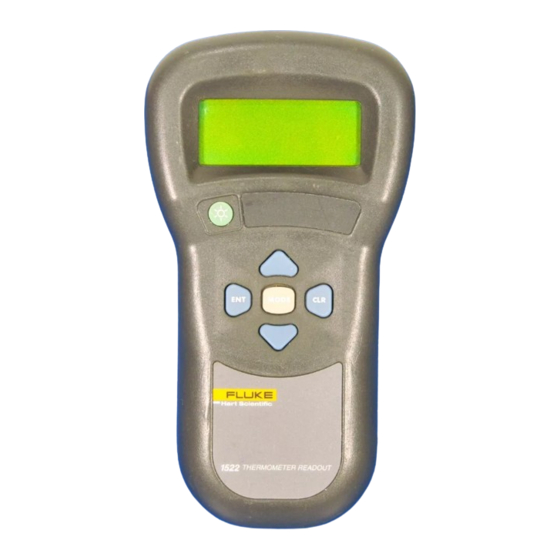
5 Parts and Controls Front View Parts and Controls The functions of the various features of the 1522 are described below. Front View The front of the 1522 features the LCD display and control buttons. Figure 1 Front View... - Page 20 1522 Handheld Thermometer Readout User’s Guide Display-The display shows the current temperature (or resistance) measure- ment on the large numeric upper portion of the display. It can also show a vari- ety of information on the smaller alphanumeric lower portion such as minimum, maximum, delta(x), and other instrument settings.
-
Page 21: Top And Side View
Stand Figure 2 Top and Side View The top and side of the 1522 feature the probe connector, DC power input, se- rial port, and infrared window. Probe Connector - At the top of the thermometer readout is the opening where the probe connector is inserted. -
Page 22: Back View
Back View See Figure 5 on page 25. Stand - The stand at the back of the 1522 can be flipped down to prop up the instrument for better viewing. Battery Compartment - Behind the stand is the compartment that contains the battery pack. -
Page 23: Accessories
The 1522's accessories and their features are described here. AC Adapter - The AC adapter recharges the internal battery pack and may also be used to supply power to operate the 1522 while the battery is being charged (see Section 6.2). - Page 24 1522 Handheld Thermometer Readout User’s Guide Ordering Information Model Type 5613 Pt-100 Ohm, 4-wire 5612 Pt-100 Ohm, 4-wire 5627–6 Pt-100 Ohm, 4-wire 5627–9 Pt-100 Ohm, 4-wire 5627–12 Pt-100 Ohm, 4-wire 5610-6 10K-ohm Thermistor 5610-9 10K-ohm Thermistor 5611 10K-ohm Thermistor 5611T...
-
Page 25: Figure 4 Infrared Dongle
PC. The INFO-CON Download Adapter software can then be used to read, edit, and write changes to the INFO-CON connector. Carrying Cases - There are two types of cases available for your 1522 ther- mometer readout. The Model 9318 case is a hard case for carrying the ther- mometer readout and a 12"... -
Page 26: General Operation
(normally 115V, optionally 230V). Connect the DC plug of the adapter into the DC input of the 1522 located on the right side. The battery charges as necessary whether or not the instrument is switched on. The power control cir-... -
Page 27: Dc Power Source
The DC power source provides power to charge the battery. It can also be used to power the 1522 while the battery is being charged. The AC adapter provided with the 1522 is intended to be used for these purposes. Use only the AC... -
Page 28: Power Button
Hart Scientific. The DC power source plugs into the DC power input on the right side of the 1522. – Figure 6 12V DC Power Source Polarity WARNING: The AC adapter contains high voltage circuits that could present danger of electric shock or fire if exposed. -
Page 29: Probe
Probe The probe is used to sense temperature and attaches to the 1522 using a Hart INFO-CON probe connector that plugs into the top of the instrument. The probe connector must be properly programmed with the correct charac- teristics of the probe for measurements to be accurate (see Section 6.6). -
Page 30: Info-Con Connector
Connectors can be purchased separately and installed onto probes by the user. The INFO-CON can be programmed di- rectly from the 1522 or from a PC with the optional Model 2372 accessory and 9972 software. -
Page 31: Figure 7 Probe Wiring Diagrams
1522 Handheld Thermometer Readout User’s Guide C1 and P1 terminals and the other single wire to the C2 and P2 terminals (which are shorted together). Hart Scientific Four-wire Connection Figure 7 Probe Wiring Diagrams Hart Scientific Three-wire Connection Short Hart Scientific... -
Page 32: Display Functions
Display Functions The insturment operates in any of several modes which determine what infor- mation is visible in the lower alphanumeric portion of the display. The MODE button sequences through the menu functions. This button can be pressed re- peatedly until a desired mode is set. The various modes are listed below in the order they appear. -
Page 33: Blank Mode
1522 Handheld Thermometer Readout User’s Guide Each of these operating modes is described in the sections that follow. Figure 8 Operating Modes Flowchart Blank Mode This mode is identified by “Blank” that temporarily appears on the display. Blank Mode button... -
Page 34: Min/Max Mode
The resolution of the displayed values match the current setting of the thermometer as set in the Resolution mode (see Section 7.8). Pressing the CLR button at anytime while in this mode clears the minimum and maximum values setting them to the last measurement. -
Page 35: Dump Data
This function allows the user to download the stored values using the se- rial port or print the data to a serial printer. To download using the serial port, the 1522 must be connected to a computer using the serial cable sent with the instrument at the time of purchase. Windows communications program must be running. -
Page 36: Clear Autolog
This function configures the rate at which data is stored into the memory of the 1522. The following rates are available: 1, 5, 10, 15, 30, or 60 seconds, 2, 5, 10, 15, 30 or 60 minutes. Scroll through the rates using the Up or Down buttons until the desired rate is shown and then press the ENT button to select the rate. -
Page 37: Dump Data
1522 Handheld Thermometer Readout User’s Guide Press the ENT button to stop autologging and to advance to the next function. 7.4.5 Dump Data? This function allows the user to download the autologged data using the serial port or print the downloaded dats to a serial printer. To download using the se- rial port, see Section 8 of this guide before selecting “Yes”... -
Page 38: Rate
button stores the selection. If the MODE button or CLR button is pressed with- out pressing ENT the unit remains unchanged. Once the unit is selected, subse- quent measurements will appear in that unit. After the Min/Max and Delta(x) modes are initiated, their values are automatically converted when changing units between °C, K, °F, or R. - Page 39 1522 Handheld Thermometer Readout User’s Guide When editing any parameter, be sure to press the ENT button through the entire line of alphanumeric characters to ensure that the edits are stored. Pressing any button other than the ENT button advances to the next function without storing the new value.
-
Page 40: Mtr Due
b4 [ITS-90 only] - Set the b4 or b5 probe coefficient R(0) [CVD only] - Set the R0 probe coefficient Alpha [CVD only] - Set the alpha probe coefficient Delta [CVD only] - Set the delta probe coefficient Beta [CVD only] - Set the beta probe coefficient b0 [Therm only] - Set the b0 probe coefficient b1 [Therm only] - Set the b1 probe coefficient b2 [Therm only] - Set the b2 probe coefficient... -
Page 41: Date
1522 Handheld Thermometer Readout User’s Guide pressed, the message “Invalid Passcode” is displayed and the instrument is re- turned to the display mode that follows the function that was active when the CAL Mode was entered. Each individual instrument has its own unique passcode. The passcode number is given on a notice provided with this instrument. -
Page 42: Its-90
7.9.8 Prb Type This function specifies the type of probe and its characterization. It allows the instrument to use the appropriate algorithm to calculate temperature from the measured resistance of the probe. The functions that follow the probe conver- sion function for setting probe characterization coefficients depend on the se- lected probe type. - Page 43 1522 Handheld Thermometer Readout User’s Guide Coefficients R(.01) Consider the following examples. Example 1: A PRT was calibrated to ITS-90 and its calibration certificate states values for coefficients R(273.16K), a4, b4, a8, and b8. Set the instrument's coefficients to the certificate values as follows.
-
Page 44: Iec751
Coefficients R(.01) 7.9.10 IEC751 The IEC751 probe type is for standard PRTs (RTDs) conforming to the IEC751 or DIN-43760 standards. This type of probe is generally low cost and has a wide operating range (–180°C to 420°C or higher), but has limited accuracy (0.15°C to 4°C). -
Page 45: Therm
1522 Handheld Thermometer Readout User’s Guide 7.9.13 THERM The THERM type is for thermistors that have unique calibration coefficients or do not match the YSI-400 specification. This type of probe generally has mod- erate cost, a limited operating range (–40°C to 150°C), excellent accuracy (0.005°C to 0.01°C) and excellent resolution (0.002°C). -
Page 46: Pcal
measurement error due to the resistance of the wires. With four wires the in- strument can completely cancel the error. The internal measurement circuit is configured differently depending on the number of wires. Note: The instrument tries to calculate a measurement even if the wire settings are incorrect. -
Page 47: Mdue
1522 Handheld Thermometer Readout User’s Guide each date segment and the ENT button to move to the next date segment on the right. Press ENT when the date is correctly entered. Press CLR to move to the next function without changing the date. -
Page 48: Rs-232 Connection
Communications Interface Remote communications allows an external device, such as a computer, to com- municate with the instrument to obtain measurement data and control its opera- tion. Communication is accomplished with various commands issued to the instrument through the RS-232 serial port. RS-232 Connection The three-conductor jack for the serial port is located on the top of the instru- ment near the probe connector. -
Page 49: Communication Command List
1522 Handheld Thermometer Readout User’s Guide The protocol for serial communications is 8 data bits, 1 stop bit, and no parity. Use no flow control. The baud rate is fixed at 2400, the linefeed to ON (all car- riage returns are followed by a linefeed (ASCII decimal 10)), and the duplex to HALF disabling echo. - Page 50 15, 30, 60, 120, 300, 600, 900, 1800, 3600 dx: -0.118 C u: C C, O, F, K, R sa: 10 0 to 10,000 res: 3 1 to 3 ti: 16:23:45 00:00:00 to 23:59:59 Hart, 1522 95001, 1.24 ver.1522, 1.24...
-
Page 51: Calibration Commands
1522 Handheld Thermometer Readout User’s Guide Description Command n Numeric data supplied by user 9 Numeric data returned to user x Character data returned to user 8.2.2 Calibration Commands The following group of commands directly or indirectly affect the accuracy of the instrument. - Page 52 Description Command Read probe wires w[ires] Set probe wires w[ires]=2/3/4 Read probe calibration date pc[al] Set probe calibration date pc[al]=yyyy-mm-dd Read probe due date pd[ue] Set probe due date pd[ue]=yyyy-mm-dd Read filter fi[lter] Set filter fi[lter]=n Read low range calibration Set low range calibration *c1=n Read high range calibration...
-
Page 53: Calibration
Calibration The 1522 should be calibrated at regular intervals to ensure that it continues to measure with proper accuracy. Calibration should only be done by qualified, authorized personnel. Required Equipment The following items are required to test and calibrate the 1522: 0 four-wire resistor (short) 25 four-wire resistor, accurate within 20 ppm (±0.0005 ) - Page 54 1522 Handheld Thermometer Readout User’s Guide 4. Verify the accuracy at 0 , 4k , 10 k , 40 k , 100 k , and 500 k . 5. Set the meter calibration date to the present date (see Section 7.9.18).
-
Page 55: Maintenance
If the AC adapter becomes damaged, have it replaced immediately. Never disassemble the AC adapter or attempt to repair it. If the instrument is used in a manner not in accordance with the equip- ment design, the operation of the thermometer readout may be impaired or safety hazards may arise. -
Page 56: Troubleshooting
Troubleshooting In case you run into difficulty while operating the 1522, this section provides some suggestions that may help you solve the problem. Below are several situa- tions that may arise followed by possible causes of the problem and suggested actions you might take. -
Page 57: Downloading Autologged Data
The 1522 Handheld Thermometer readout stores up to 10,000 readings in its autolog memory. These readings can be downloaded to a computer using the RS-232 serial port. By default, the 1522 serial port operates at 2400 baud. However, when downloading autologged readings over the serial port or print- ing to a serial printer, the instrument temporarily changes its baud rate to 9600 baud to reduce the download time. -
Page 58: Troubleshooting
If you wish to abort the download process before it has completed, press 'CLR' on the front panel of the 1522. The 1522 sets its baud rate back to 2400 baud automatically. Reset the terminal program's baud rate to 2400 baud. -
Page 59: Ce Comments
1522 Handheld Thermometer Readout User’s Guide sion. For best results, place the IR dongle and the IR window on the 1522 at an angle of 0° and within 0.5 meters. Figure 10 Infrared Dongle Position 11.4 CE Comments 11.4.1 EMC Directive Hart Scientific’s equipment has been tested to meet the European Electromag-... -
Page 60: Emission Testing
11 Troubleshooting CE Comments Electric Fast Transit (EFT, Burst, IEC 61000-4-4). If the instrument is sub- jected to EFT conditions at 2kV, the instrument may require the user to cycle the power to return to normal operation. 11.4.1.2 Emission Testing The instrument fulfills the limit requirements for Class A equipment but does not fulfill the limit requirements for Class B equipment.
Need help?
Do you have a question about the Hart Scientific 1522 and is the answer not in the manual?
Questions and answers