MUTOH VC-600 User Manual
Sign cutting plotter
Hide thumbs
Also See for VC-600:
- User manual (108 pages) ,
- User manual (107 pages) ,
- Maintenance manual (63 pages)

Related Manuals for MUTOH VC-600


Summary of Contents for MUTOH VC-600
- Page 1 USER MANUAL Sign Cutting Plotter VC-600 VC-1300 VC-1800 Read This Manual Before Using The Plotter. Rev No. V5a 2015 Jan...
- Page 2 Caution No part of this product or publication may be reproduced, copied, or transmitted in any form or by any means, except for personal use, without the permission of MUTOH INDUSTRIES LTD. The product and the contents of this publication may be changed without prior notification.
-
Page 3: Important Information
ValueCut USER MANUAL Important Information Important Information Thank you for purchasing the ValueCut Cutting Plotter. Before you use the cutting plotter, please make sure that you have read the safety precautions and instructions below. Caution SAFETY PRECAUTION For safety concern, please always hold the cutter firmly from the bottom while moving it. - Page 4 Important Information ValueCut USER MANUAL Hazardous moving parts keep fingers and other body parts away! Do not shake or drop the blade holder, a blade tip can fly out. During an operation, do not touch any of the moving parts of this machine (such as the carriage).
- Page 5 ValueCut USER MANUAL Important Information Operation precaution Always put the pinch rollers within the white marks. Note: Never press the top release grip (the release grip is fully pressed when a clip sound is heard) and pull the bottom release grip at the same time as the pictures shown below.
-
Page 6: Table Of Contents
2 Installatopn ............15 2.1 Precaution ....................... 15 2.2 Stand & Flexible Media Support System (VC-1300/1800) ........16 2.3 Desktop Flexible Media Support System (VC-600) ..........22 2.4 Instruction of Damper Roller ................. 24 2.5 Installation of Media Basket System ..............25 2.6 Cutting Pad Installation .................. - Page 7 ValueCut USER MANUAL Table of Contents 4.1.2 Loading the Roll Media ......................45 4.2 Tracking Performance .................... 48 4.3 Cutting Force and Offset Adjustment ..............49 4.4 How to Cut 3mm Letters ..................50 4.5 How to Make A Long Plot ..................50 4.6 When Completing the Cutting Job ................
- Page 8 Table of Contents ValueCut USER MANUAL 8.5.2 Change unit of measures used in the Production Manager ............ 74 8.6 Basic Settings ......................75 8.6.1 Overview of the FlexiSTARTER screen .................. 75 8.6.2 Standard Toolbar ........................76 8.6.3 Main Toolbar ........................... 77 8.7 Create the Character ....................
-
Page 9: General Information
The package of the ValueCut model contents the items listed below, please check carefully. If you find any item missing, please consult your local dealer for further assistance. 1. Cutting Plotter Main unit 2. Stand Set ( for VC-1300/1800 only )(Optional for VC-600) 2 piece of T-shape stand ... - Page 10 4 pieces of Plastic Foot 4 pieces of M4 screws 12 pieces of M6 screws 1 piece of M4 L-shape hexagon screw driver 4.Media Basket (VC-1300/1800 only) (VC-600 : opt.) 2 pieces of Basket Arm 2 pieces of Basket Rod ...
-
Page 11: Production Features
ValueCut USER MANUAL General Information 1.3 Production Features The following are the main features of the ValueCut series cutting plotters: ‧ Tri-port connectivity provides you with greater flexibility ‧ Up to 600-gram cutting force ‧ Up to 60-inch/per second cutting speed ‧... -
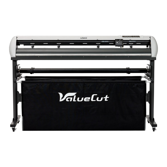
Page 12: Appearance Of Valuecut
General Information ValueCut USER MANUAL 1.4 Appearance of ValueCut 1.4.1 The Front View Grid Drums – move the Tool Carriage performs the – media back and forth cutting with the installed blade and during operation. pen with AAS module. Control panel consists of 14 –... -
Page 13: The Back Vuew
ValueCut USER MANUAL General Information 1.4.2 The Back Vuew Lever – raises or lowers the pinch rollers. Pinch Rollers – hold the media during cutting. Figure 1-2 1.4.3 The Whole View of ValueCut Roll Holder – holds and supplies the roll media for cutting. -
Page 14: The Left Side View
General Information ValueCut USER MANUAL 1.4.4 The Left Side View Power Switch – On when switches to [I]; Off to Circuit Breaker – 3 Amp. Figure 1-4 AC Power Connector – used to insert the AC power 1.4.5 The Right Side View Serial Interface Connector (RS232C) –... -
Page 15: Installatopn
ValueCut USER MANUAL Installation 2 Installatopn 2.1 Precaution Please read the following information carefully before you start installation. Note: Make sure the power switch is off before installing the cutting plotter. Carefully handle the cutter to prevent any injuries. ... -
Page 16: Stand & Flexible Media Support System (Vc-1300/1800)
Installation ValueCut USER MANUAL 2.2 Stand & Flexible Media Support System (VC-1300/1800) Step 1 Please examine supplied items in the accessory box of stand carton: 2 pieces of base beams 2 pieces of side beams 1 piece of stand beam ... - Page 17 ValueCut USER MANUAL Installation Step 3 Place the stand beam upright on the T-stand and follow number (1) (2)to assemble. (See Figure 2-4 & 2-5) (1) T-Stand (2) Stand beam Figure 2-4 Figure 2-5 Step 4 Position the stand beam perpendicularly to part (1)and put the screws into the holes and tighten them as Figure 2-5.
- Page 18 Installation ValueCut USER MANUAL Step 5 Remove the cutting plotter from the carton. Position your stand under the plotter, and then insert the screws into the holes on plotter’s bottom and tighten them up as shown in Figure 2-6. Screw(M6) Figure 2-6 を...
- Page 19 ValueCut USER MANUAL Installation Step 6 Insert the roll holder support with the screws into the holes of the stand, and then tighten them up as shown in Figure 2-7. You could decide roll holder support’s position by inserting into different holes. 3 screws Figure 2-7 Roll holder support...
- Page 20 Installation ValueCut USER MANUAL Step 8 Turn the screw counter-clockwisely for around three times after unpacking roll holder 2 ( Figure 2-9) . Figure 2-9 Step 9 Insert the end of the roll holder without the damper into the left roll holder support and then insert the end of the roll holder with the damper into the right roll holder support.
- Page 21 ValueCut USER MANUAL Installation Step 10 Tighten the screw on the damper until it is securely attached to the right roll holder support ( Figure 2-11) . Figure 2-11 Step 11 Lastly, the complete picture will be shown like below ( Figure 2-12 ). Figure 2-12 V5a 2015 Jan...
-
Page 22: Desktop Flexible Media Support System (Vc-600)
Installation ValueCut USER MANUAL 2.3 Desktop Flexible Media Support System (VC-600) Step 1 Please examine the following items in stand carton’s accessory box: 1 set of Roll Media Flange (2 pieces) 1 set of Roll Holder (2 pieces) ... - Page 23 ValueCut USER MANUAL Installation Step 3 Position the Desktop Support Brackets beside the Roll Holder Support and insert M6 screws into the Roll Holder Support and tighten them with M6 L-shape screw driver. (Refer to Figure 2-14 at the left). Step 4 Put the bottom of machine in lateral, and position the Roll Holder Assembly beside the bottom of the machine.
-
Page 24: Instruction Of Damper Roller
Installation ValueCut USER MANUAL 2.4 Instruction of Damper Roller Step 1 Turn the wheel as instructed below to adjust damping. The bigger the number is, the stronger the damping. The volume symbol sticker indicates the damping level (Figure 2-18, 2-19). Figure 2-18 Figure 2-19 V5a 2015 Jan... -
Page 25: Installation Of Media Basket System
ValueCut USER MANUAL Installation 2.5 Installation of Media Basket System Step 1 Please examine the supplied items in the accessory box 2 pieces of basket arms 2 pieces of basket rods 1 piece of basket 2 pieces of fixtures (for basket arms) 8 pieces of M3 screws ... - Page 26 Installation ValueCut USER MANUAL Step 3 Insert the basket rods to the basket holes (See Figure 2-21) Basket rods Basket Figure 2-21 Step 4 Loosen the basket screws from the basket arms. Position the basket rod in front of the basket arms and insert the basket screws into the holes on the basket rod and tighten them.
- Page 27 ValueCut USER MANUAL Installation Step 5 The complete Media Basket System will be like Figure 2-23. Figure 2-23 V5a 2015 Jan...
-
Page 28: Cutting Pad Installation
Installation ValueCut USER MANUAL 2.6 Cutting Pad Installation 1 piece of cutting pad is included in the accessory pack. Follow the instruction below to install a new cutting pad when the existing pad is worn out. Step 1 Carefully remove the cutting pad from the unit. Figure 2-24 Step 2 Remove the remaining adhesive on the groove with alcohol or cleaning naphtha. - Page 29 ValueCut USER MANUAL Installation Step 3 Attach the new cutting pad to the groove after unrolling it and removing the backing sheet and the installation process is completed. Figure 2-26 Figure 2-27 V5a 2015 Jan...
-
Page 30: Blade Installation
Installation ValueCut USER MANUAL 2.7 Blade Installation Figure 2-28 is the illustrator of the blade holder. Insert a blade into the bottom of the blade holder and remove the blade by pushing the pin. Make sure that your fingers are away from the blade tip. Adjustment depth knob Outward ring Figure 2-28... - Page 31 ValueCut USER MANUAL Installation Step 4 Insert the blade holder into tool carriage. Please note the outward ring of the holder must put into the grooves of carriage firmly (see Figure 2-32), then fasten the case (Figure2-33). Figure 2-32 Figure 2-33 Step 5 Use the reversing steps to remove the blade holder.
-
Page 32: Automatic Blade Length Detection
Installation ValueCut USER MANUAL 2.8 Automatic Blade Length Detection Figure 2-34 is the new blade holder with a scale and the carriage with a mark. This blade holder detects blade length automatically and shows how the knob needs to be turned on the LCM. Scale 1 unit Mark... - Page 33 ValueCut USER MANUAL Installation 4. When blade holder and blade length tests are finished, the screen will show you to what degree (the unit of the value following “CW” or “CCW” is “circle”) and in which direction [CW (clockwise) or CCW (counterclockwise)] you should turn the adjustment knob.
-
Page 34: Cable Connection
Installation ValueCut USER MANUAL 2.9 Cable Connection The cutting plotter communicates with a computer through a USB (Universal Serial Bus) or a Serial port (RS-232C). This chapter shows you how to connect the cutting plotter to a host computer and how to set up the computer/cutting plotter interconnection. Note: When USB connection is enabled, both parallel port and serial port will be disabled automatically Serial port... -
Page 35: The Control Panel
ValueCut USER MANUAL Control Panel 3 The Control Panel This chapter describes the button operations with the LCM menu flowcharts of ValueCut. When the cutting plotter is ready for use as described in Chapter 1 & 2, all functions are under default parameters. -
Page 36: Menu In On-Line Mode
Control Panel ValueCut USER MANUAL 3.2 Menu in On-line mode Power On ValueCut in processing MUTOH LCM Version 1.3 Firmware V3.01 VC-1300 Place Media And Then Lower Up The Lever Roll Edge Single ~ Key | Key } Key Sizing Media Width... -
Page 37: Menu In Off-Line Mode
ValueCut USER MANUAL Control Panel 3.3 Menu in Off-line Mode Press [ON/OFF LINE] to switch to the offline mode Offline For System Setup Force: gf ~ [ FORCE] 5~600 with an increment of 5(gram force) Ok:ENTER| Offset: 0.250 mm ~ [ OFFSET ] Ok:ENTER| 0.000~1.000 with an increment of 0.025(mm) - Page 38 Control Panel ValueCut USER MANUAL Offline For System Setup use ~| to select from 1S to 4S; [ENTER] to adjust the 72 F 80 O0.250M Select:{} Ok:ENTER| parameters [TOOL SELECT ] Set Smoothing Cut Select:{} Ok:ENTER OverCut: 0.00 mm ~ OverCut:0.00-3.00mm with an Select:{} Ok:ENTER|...
-
Page 39: Menu Items
ValueCut USER MANUAL Control Panel 3.4 Menu Items Below describes the functions of menu items Menu or Key Function Setting Default --- Media sizing --- Place Media To instruct the user to lower the lever after the material is And Then loaded. - Page 40 Control Panel ValueCut USER MANUAL 300g-449g, the maximum cutting speed would be 30 cm/sec and the cutting quality would be Fine Mode (0.5g) [ SPEED ] Speed To set or modify tool down speed at horizontal moving. 3~153cm/sec; 72cm/sec 3cm/sec per step Up Speed To set or modify tool up speed at horizontal moving.
- Page 41 ValueCut USER MANUAL Control Panel [ TOOL SELECT ] Set Smoothing To enable smooth-cutting function. Enable This function aims to make connections smoother and is suggested to be disabled when cutting small-sized images or characters Over Cut To generate an overcut to facilitate weeding. 0.00mm-3.00mm 0.00mm This function mainly applies to thick materials, aiming to...
- Page 42 Control Panel ValueCut USER MANUAL 9600, o, 7, 1, p 9600pbs, 7 Bits with ODD Parity 9600, e, 7, 1, p 9600pbs, 7 Bits with EVEN Parity 9600, n, 8, 1, p 9600pbs, 8 Bits with NO Parity 9600, o, 8, 1, p 9600pbs, 8 Bits with ODD Parity 9600, e, 8, 1, p 9600pbs, 8 Bits with EVEN Parity...
-
Page 43: Operation
ValueCut USER MANUAL Operation 4 Operation 4.1 Media Loading 4.1.1 Loading the Sheet Media To load the media properly, please follow the procedures listed below: Step 1 Use the lever on the upper right side of the cutting plotter to raise or lower down pinch rollers. Pull the lever forward until it makes a clicking sound then the pinch rollers are raised ( Figure 4-1 ). - Page 44 Operation ValueCut USER MANUAL Step 3 Then move the pinch rollers manually to the proper position. Be sure the pinch rollers must be positioned above the grid drum. The white marks on the top trail will remind you where the grid drums are (Figure 4-3).
-
Page 45: Loading The Roll Media
ValueCut USER MANUAL Operation Note: Please pull up the bottom of all pinch rollers (Figure 4-5) before the lever is pushed backwards to ensure accurate media width detection. Pull up bottom to release grip Enable Figure 4-5 4.1.2 Loading the Roll Media Step 1 Put the roll media guide bushes on two roll holders (Figure 4-6). - Page 46 Operation ValueCut USER MANUAL Step 2 -- Option A (Recommended) Insert the two roll holders into the roll media support set then place the roll media directly between the two roll holders ( Figure 4-7 ). Figure 4-7 Figure 4-8 -- Option B (Use the media flanges ) ...
- Page 47 ValueCut USER MANUAL Operation 図 4-10 図 4-11 Step 4 Turn the roll downward to make an equal tension across the media (Figure 4-11) Step 5 Move the pinch rollers to the appraise location and note that the pinch rollers must be positioned above the grid drums.
-
Page 48: Tracking Performance
Operation ValueCut USER MANUAL 4.2 Tracking Performance In order to achieve the best tracking performance for a long plot, we recommend some significant media loading procedures described as follows: If the media length is less than 4 meters, leave the margin of 0.5mm—25mm in the left and right edges of the media (Figure 4-12). -
Page 49: Cutting Force And Offset Adjustment
ValueCut USER MANUAL Operation 4.3 Cutting Force and Offset Adjustment Before sending your designs for cutting, you may perform a “cut test” to generate satisfactory cutting results. The “Cut Test” should be repeated until the appropriate cutting conditions for the media are discovered. -
Page 50: How To Cut 3Mm Letters
Operation ValueCut USER MANUAL 4.4 How to Cut 3mm Letters To obtain good quality output, narrow media is recommended. However, if wide media is used, you should: Position two pinch rollers as close as possible to both edges of the cutting area. Make sure the loaded media is held flat with equal tension across the platen. -
Page 51: When Completing The Cutting Job
ValueCut USER MANUAL Operation Then turn the roll downward to make an equal tension across the media (See Figure 4-16) Make sure that the media tension is equally distributed from left to right. If the media is not tight enough against the platen, it will cause tracking problems. -
Page 52: Automatic Aligning System Ii
Automatic Aligning System ValueCut USER MANUAL 5 Automatic Aligning System II 5.1 Introduction The ValueCut series cutting plotters feature a standard Automatic Aligning System (AAS II) to guarantee precise contour cutting quality by detecting the registration marks printed around the graphic. Notice ... -
Page 53: Aas Calibrating The System
ValueCut USER MANUAL Automatic Aligning System 5.2 AAS Calibrating the System The AAS system has one calibration procedures to ensure maximum accuracy of AAS operation. To operate the AAS you need to learn about the method of media feeding firstly. (Refer to 4.1 Media Loading.) 5.2.1 Media Calibration Media Calibration is to ensure the sensor being able to recognize the registration marks. -
Page 54: Aas Ii On Valuecut
Copies. Note that before print out your designs by inkjet printers, the registration marks have to be created on your graphic designs by cutting software. Hand-made marks or drawings won’t be reorganized by Mutoh cutting plotters. 1. 4-Point Positioning This is the basic mark pattern that AAS II will auto detect four registration marks and contour cut images inside those marks. - Page 55 ValueCut USER MANUAL Automatic Aligning System High Precision Long Picture Cutting ValueCut performs segmental cutting to enhance output qualities. The object will be output following the Data Block pattern based on the Segmental Positioning parameters. Cutting sequence: Date Block1-> Date Block2-> Date Block3- >Date Block4 3.
-
Page 56: Printer Test
Automatic Aligning System ValueCut USER MANUAL 4. Automatic Distinction of the Plot Direction For the convenience of users, ValueCut automatically detects the feeding direction of the material when performing contour cutting. Figure 5-1 shows the Registration Mark detection sequence when the material is fed in the standard way (1->2->3->4) while Figure 5-2 is how ValueCut detects registration marks (3->4->1->2) when the material is reversely fed. - Page 57 ValueCut USER MANUAL Automatic Aligning System AAS offset Calibration.pdf (Print data) AAS offset Calibration.plt (Cutting data) Print out the Print data by 100%. ( Please use high precision printer) Load the graphic to ValueCut and sent the Cutting data to test the cutting job You can output the cutting data from Production Manager of FlexiSTARTER.
-
Page 58: Registration Mark Offset Range
Automatic Aligning System ValueCut USER MANUAL Note: Before adjusting the AAS II settings, please proceed scaling for width and length. The blade offset value isn’t set for this test graphic, please set it according to the blade you use. - Page 59 ValueCut USER MANUAL Automatic Aligning System TIPS1: Leave some space between the graphic and contour line. TIPS2: Create the contour in a separate layer and assign a different color for it. Add registration marks around the graphic. Note: The Multiple Copies function is also available. It automatically copy the graphic and registration marks.
-
Page 60: Tips For Aas
Automatic Aligning System ValueCut USER MANUAL Step 3 Print the Graphics Print the graphic and the marks with your printer (Scaling = 100%). When printing on a roll media, make sure the orientation as following: Step 4 The Origin Mark is is different from the rest registration marks. -
Page 61: Maintenance
ValueCut USER MANUAL Maintenance 6 Maintenance This chapter explains the basic maintenance (i.e. cleaning the cutting plotter) required for the cutting plotter. Except for the procedures mentioned below, all other maintenance must be performed by a qualified service technician. 6.1 Cleaning the Cutting Plotter Cleaning the machine properly and regularly will ensure optimal performance out of your machine. -
Page 62: Cleaning The Grid Drum
Maintenance ValueCut USER MANUAL 6.2 Cleaning the Grid Drum Turn off the cutting plotter, and move the tool carriage away from the area needed to be cleaned. Raise the pinch rollers and move them away from the grid drum for cleaning. Use a bristle brush (a toothbrush is acceptable) to remove dust from the drum surface. -
Page 63: Trouble Shooting
ValueCut USER MANUAL Trouble Shooting 7 Trouble Shooting This chapter is to help you correct some common problems you may come across. Prior to getting into the details of this chapter, please be sure that your application environment is compatible with the cutting plotter. Note: Before having your cutting plotter serviced, please make sure that the malfunction is in your cutting plotter, not the result of an interface problem or a malfunction in your computer or a software problem. -
Page 64: Operational Problems
Trouble Shooting ValueCut USER MANUAL 7.2 Operational Problems Some mechanical problems or failure during operation will cause some problems. If the problem still exists after the recommended actions have been taken, have your cutting plotter serviced. 7.2.1 LCM Error Messages The error messages shown on the LCM present the problem first, and followed by recommended actions. -
Page 65: Other Operational Problems
ValueCut USER MANUAL Trouble Shooting 7.2.2 Other operational problems 1. Pinch rollers Note: Never press the top release grip (the release grip is fully pressed when a clip sound is heard) and pull the bottom release grip at the same time as the pictures shown below. This will prevent you from disabling the pinch roller as the stop bar will not reach the correct position and therefore will not be functioning. - Page 66 Trouble Shooting ValueCut USER MANUAL 2. Media is rolled up during the cutting process Step 1 Turn off the cutting plotter Step 2 Move the pinch rollers to the side Step 3 Pull the lever up Step 4 Trim off the rolled up part of the media Step 5 Reload the material 3 The media runs diagonally Step 1 Stop the operation...
-
Page 67: Cutting Plotter/Computer Communication Problems
ValueCut USER MANUAL Trouble Shooting 7.3 Cutting Plotter/Computer Communication Problems The messages showed below present problems in relation to cutting plotter/computer communication. Is the connection cable connected to Communication Error the cutting plotter and computer Setup: MISC. key properly? Has the interface setting been Refer to Chapter 2 - done correctly? Connecting your cutting... -
Page 68: Software Problems
Trouble Shooting ValueCut USER MANUAL 7.4 Software Problems Check the following first: Does your software package indicate that it will work with your computer and cutting plotter? Does your software support HP-GL and HP-GL/2 drivers? (* check the configuration settings of your software.) Does the cutting plotter interface Most well known cutting softwares in match the requirements of your... -
Page 69: Cutting Quality Problems
ValueCut USER MANUAL Trouble Shooting 7.5 Cutting Quality Problems Note: The daily maintenance of your cutting plotter is very important. Be sure to clean up the grid drum and pinch rollers regularly for better cutting accuracy and output quality. Is the blade installed correctly and the blade holder fastened securely? Refer to Chapter 2.4 Is the blade dull or... -
Page 70: Flexistarter Quick Start Guide
FlexiSTARTER Quick Start Guide ValueCut USER MANUAL 8 FlexiSTARTER Quick Start Guide 8.1 Introduction FlexiSTARTER ValueCut Edition is a special software to plot AI / EPS / PDF...etc format data from the ValueCut with a simple operation. 8.2 Install of the FlexiSTARTER Note: Please do not put the attached the USB Hardware Key in the computer until after software is installed. -
Page 71: Start Up Of The Flexistarter
ValueCut USER MANUAL FlexiSTARTER Quick Start Guide First of all, after the Install Manager screen appears, put a 3:password in the attached password sheet into "Password". Then, USER ID may show up in a:"User Number". Select "FlexiSTARTER ValueCut Edition" in 4:"Product" and "English" in 5:"Language" and click on Finally, the installation is done. -
Page 72: Add Device By Using The Production Manager
When the Production Manager starts up for the first time after the installation of the program, the Add Setup window appears as the diagram below. This screen enables you to set up device of the ValueCut. You can see "Mutoh" selected in the box saying "What is the brand name of your vinyl cutter?"... -
Page 73: Initial Settings Of The Production Manager
ValueCut USER MANUAL FlexiSTARTER Quick Start Guide 8.5 Initial Settings of the Production Manager 8.5.1 Change to the setting of leaving job that finishes running The Production Manager window can hold a job following the figure below. This is how to leave cutting job in the screen after the cut. -
Page 74: Change Unit Of Measures Used In The Production Manager
FlexiSTARTER Quick Start Guide ValueCut USER MANUAL 8.5.2 Change unit of measures used in the Production Manager Open the Preferences window from the Edition menu of the Production Manager and change settings as follows. 1. Change the unit. 2. Select the precision and press the button. -
Page 75: Basic Settings
ValueCut USER MANUAL FlexiSTARTER Quick Start Guide 8.6 Basic Settings 8.6.1 Overview of the FlexiSTARTER screen After the FlexiSTARTER starts up, the screen is as follows. Change a setting of length following the instruction written in blue. Origin: Clicking and dragging makes it possible to change the original point of the scale. -
Page 76: Standard Toolbar
FlexiSTARTER Quick Start Guide ValueCut USER MANUAL Additionally, select "Design Central" and "Fill/Stroke Editor" from the View Window menu and open the screens. These screens are frequency in use. The displayed content of the Design Central screen depends on a selected tool. The figure example right above means a size of paper in the Design Central window. -
Page 77: Main Toolbar
ValueCut USER MANUAL FlexiSTARTER Quick Start Guide 8.6.3 Main Toolbar The tools in parenthesis are the extension tools that may appear when you click on them for a while. ): Select Tool that selects an object ): Text Tool that makes it possible to enter text ): Bezier Path Tool that creates a path ): Rectangle Tool that makes a rectangle : Select Point Tool that makes a point of path... -
Page 78: Create The Character
FlexiSTARTER Quick Start Guide ValueCut USER MANUAL 8.7 Create the Character For an instance, construct characters: "ABC" 100 millimeters height. Click on in the main toolbar and click in the design area discretionally. Assign 100millimeters in height in the Design Central window. Then, enter "ABC"... -
Page 79: Cut/Plot Window
ValueCut USER MANUAL FlexiSTARTER Quick Start Guide 8.7.1 Cut/Plot Window The Cut/Plot window has four tabs as follows: General tab Set up: Material size Position Size Copies Panel tab Set up for job that exceeds media size: Panel size Title Overlap... -
Page 80: Cut The Character
FlexiSTARTER Quick Start Guide ValueCut USER MANUAL Advanced tab Set up applicative cutting job. Let's try to cut. Set somewhere around A3 size sheet sideways to the ValueCut. Refer to the ValueCut manual about how to load a sheet. 8.8 Cut the Character Execute cutting job in the Cut/Plot window with each of the tabs as follows: Click on , then media size loaded to... - Page 81 ValueCut USER MANUAL FlexiSTARTER Quick Start Guide Place a check mark in "Weed border". Click on , then the window may open. Select "Cut First" in and click and close the window. Click on to send cutting data to the ValueCut, then the cutting job may V5a 2015 Jan...
-
Page 82: Create Date Of The Contour Cut Line
Select "Open" from the file menu in the FlexiSTARTER. Read in the sample data: "Airborne.ai." "Airborne.ai" is in these folders as follows: As in the 64bit OS C:¥Program Files (x86)¥Mutoh¥FlexiSTARTER ValueCut Edition¥Samples¥Illustrator As in the 32bit OS C:¥Program Files¥Mutoh¥FlexiSTARTER ValueCut Edition¥Samples¥Illustrator V5a 2015 Jan... -
Page 83: Create Data Of The Contour Cut Line
ValueCut USER MANUAL FlexiSTARTER Quick Start Guide 8.9.3 Create data of the contour cut line Hover the mouse pointer over the whole image. Select "Cut Contour" from the Effects menu. Set up in the Design Central window as follows: Select "Contour" b. -
Page 84: Cut Contour Mark
Select it in the case of the standard cut. The ValueCut detects four reg. mark and makes the alignment. Mutoh Segment Positioning For the purpose of a long length plot cut, this Mutoh segment positioning prints the reg. marks at 50-centimeter intervals toward the same direction of the media feed. When the ValueCut cuts, detects all the marks and makes the alignment. -
Page 85: Create A Cut Contour Mark
The contour cut mark may be created. Assign a kind of the mark from the Design Central window. This time, Mutoh 4 Point Positioning is applied. Set up in the Design Central window as follows: Select "Mutoh 4 Point Positioning". -
Page 86: Cut Contour
FlexiSTARTER Quick Start Guide ValueCut USER MANUAL 8.10 Cut Contour 8.10.1 Image Print Print on a printer registered in a computer from the FlexiSTARTER ValueCut Edition. Select "Print…" from the File menu and print cutting data of the cut contour. As to the printing procedure, refer to the printer manual you use. -
Page 87: Cut Contour
ValueCut USER MANUAL FlexiSTARTER Quick Start Guide 8.10.3 Cut Contour The basic setup is the same as the Cut/Plot window. The ValueCut executes to cut the contour in the following process. Click on to detect and present media size attached to the ValueCut. Select "Send now"... -
Page 88: Feature List
FlexiSTARTER Quick Start Guide ValueCut USER MANUAL 8.11 Feature List The following table is a feature lists of flexi each series. Please refer to the column of "FlexiSTARTER". Getting Started Working with Text ○ ○ Navigator View Text Block Size ○... - Page 89 ValueCut USER MANUAL FlexiSTARTER Quick Start Guide Working with Effects ○ ○ Fuse ○ Separate Overlap ○ ○ Stripe ○ Blend ○ Lens ○ Underbase ○ Finisher ○ ○ Color Trapping ○ ○ Graphic Styles ○ ○ ○ Contour Working with Measurements and Labels ○...
-
Page 90: Troubleshooting
FlexiSTARTER Quick Start Guide ValueCut USER MANUAL 8.12 Troubleshooting 8.12.1 Can not send the data from FlexiSTARTER Confirm the port setting of FlexiSTARTER. When you turn on the plotter after the FlexiSTARTER, you may not be able to send data to the plotter. Set the output port to "USB_Printer_0"... -
Page 91: Appendix
Mutoh reserves the right to change the specifications at any time without notice. The above listed specification values are effective only when operated with media certified by Mutoh. V5a 2015 Jan... -
Page 92: Blade Specification
Appendix ValueCut USER MANUAL 9.2 Blade Specification For cutting thick fluorescent and reflective vinyl. Also for cutting detailed work in standard vinyl. The blade is 45° with Red Cap(5-unit package), 0.25 mm offset For cutting reflective vinyl, cardboard, sandblast, flock, and stencil sharp edge. -
Page 93: About The Tool
ValueCut USER MANUAL Appendix 9.3 About the Tool A generic term referring to the blade that cuts the sheet, the pen that does plotting, and the LED bombsight (option) used for pointing to the reference point. OFFSET is the distance that the blade tip is displaced from the centerline of the blade. Blade Central line Blade tip... -
Page 94: Consumable And Optional Item List
Cutting Pad (W6mm*L10m) VC-CMAT Pouncing Tool assembly (Diameter: 1.5mm) VC-PT VC-PMAT Pouncing Pad(L=1.5m) Tweezers(L=11cm W=0.85cm ) VC-TW Safe Blade VC-SB Optional Items Part Number Item Name VC-STD600 Stand for VC-600 (with Basket) Add-on flat table for VC-600 VC-TBL V5a 2015 Jan... - Page 96 Tel:1-480-968-7772 Tel:32-(0)59-561400 Tel:49-(0)211-385474-0 Fax:81-(0)3-6758-7025 Fax:1-480-968-7990 Fax:32-(0)59-807117 Fax:49-(0)211-385474-74 E-mail:ibd@mutoh.co.jp E-mail:sales@mutuoh.com E-mail:mutoh@mutoh.be E-mail:vertrieb@mutoh.de http://www.mutoh.co.jp/en/ http://www.mutoh.com/ http://www.mutoh.eu/ http://www.mutoh.de/ MUTOH North Europe S.A. MUTOH HONGKONG LTD. MUTOH SINGAPORE PTE.LTD. MUTOH AUSTRALIA PTY. LTD.. Tel:352-445-906 Tel:852-2377-3411 Tel:65-6325-3150 Tel:61-2-9437-1366 Fax:352-447-093 Fax:852-2377-3422 Fax:65-6220-4342 Fax:61-2-9436-2871 E-mail:info@mutohnorth.eu http://www.mutoh.co.jp/en/ http://www.mutoh.co.jp/en/ E-mail:sales@mutoh-au.com...
Need help?
Do you have a question about the VC-600 and is the answer not in the manual?
Questions and answers