
Related Manuals for MUTOH RJ-901M


Summary of Contents for MUTOH RJ-901M
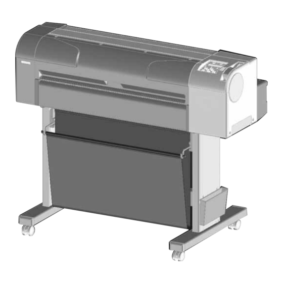
- Page 1 MAINTENANCE MANUAL Full-Color Inkjet Plotter RJ-900C / RJ-901C / RJ-901M Use this manual for the maintenance and inspection of machine. Rev. RJ91CME-M-01...
- Page 3 3. Trademark Mentioned in this Manual • MUTOH, Draf Station, RJ-901C, RJ-901M, RJ-900C, MH-GL, MH-GL2, and MH-RTL are registered trademarks or product names of MUTOH INDUSTRIES LTD. • Centronics and BiCentronics are registered trademarks or product names of Centronics Data Computer Corporation.
- Page 4 Warranty Limitations Warranty Limitations 1. MUTOH INDUSTRIES LTD. warrants part repair or replacement as a sole measure only if a failure is found in the system or in the materials and workmanship of the product the seller produced. However, if the cause of failure is uncertain, decide the action after due mutual consultation.
- Page 5 About this Manual 1. Purpose and Target Readers This manual explains preparations needed before maintaining and checking operations for MUTOH Full Color Ink Jet Plotter (RJ-901C, RJ-901M and RJ-900C). This is a common maintenance manual for RJ-901C, RJ-901M and RJ-900C.
- Page 6 RJ-900C/RJ-901C/RJ-901M Maintenance Manual About this Manual 3. Manual Notation The following symbols are used in this manual for easier understanding of the information. Symbol Meaning Must be followed carefully to avoid death or serious bodily injury WARNING Must be observed to avoid slight or moderate bodily injury or damage to...
-
Page 7: Table Of Contents
RJ-900C/RJ-901C/RJ-901M Maintenance Manual GENERAL TABLE OF CONTENTS 1 Safety Instructions 1.1 Introduction ..........1-2 1.2 Warnings, Cautions and Notes . - Page 8 RJ-900C/RJ-901C/RJ-901M Maintenance Manual 3.4 Options/Supplies List......... . 3-8 3.4.1...
- Page 9 RJ-900C/RJ-901C/RJ-901M Maintenance Manual 4.7.2 Replacing Pump Cap Assembly......4-52 4.7.3 Replacing Cleaner Head (Cleaning Wiper) .
- Page 10 RJ-900C/RJ-901C/RJ-901M Maintenance Manual 5.5.6 CW Adjustment ......... . 5-31 5.5.7...
- Page 11 RJ-900C/RJ-901C/RJ-901M Maintenance Manual Adjustment 7.1 Introduction ..........7-3 7.2 Adjustment Item .
- Page 12 RJ-900C/RJ-901C/RJ-901M Maintenance Manual 8.4 Lubrication/Bonding ......... . 8-6 8.5 Transportation of Plotter .
- Page 13 RJ-900C/RJ-901C/RJ-901M Maintenance Manual 1 Safety Instructions 1 Safety Instructions Introduction ..................... 1- 2 Warnings, Cautions and Notes.............. 1- 2 Important Safety Instructions ..............1- 3 Warning Labels ..................1- 6 1.4.1 Handling the Warning Labels............1-6 1.4.2 Locations and Types of Warning Labels........1-7 Operation Labels..................
-
Page 14: Safety Instructions
1 Safety Instructions RJ-900C/RJ-901C/RJ-901M Maintenance Manual 1.1 Introduction This chapter explains the meaning of safety terms for personnel who installs, operates, or maintains this equipment, important safety instructions, and the warning labels attached to the equipment. WARNING Make sure to follow all instructions and warnings on this manual when installing, operating, or maintaining the equipment. -
Page 15: Important Safety Instructions
RJ-900C/RJ-901C/RJ-901M Maintenance Manual 1 Safety Instructions 1.3 Important Safety Instructions General safety instructions that must be observed to use the equipment safely are explained below. WARNING • Do not place the plotter in the following areas. Doing so may result in the plotter tipping or falling over and causing injury. - Page 16 • If you need to operate the plotter with the cover removed for maintenance, be careful not to get hurt by the driving parts. • Never lube the plotter mechanism with lube other than that designated by MUTOH. Doing so may damage the parts or shorten the lifetime.
- Page 17 RJ-900C/RJ-901C/RJ-901M Maintenance Manual 1 Safety Instructions • Make sure there is sufficient space around the plotter when performing maintenance work. • Maintenance must be done by more than two person for the following work. • When disassembling or reassembling the product and the optional stand •...
-
Page 18: Warning Labels
1 Safety Instructions RJ-900C/RJ-901C/RJ-901M Maintenance Manual 1.4 Warning Labels The handling, attachment locations, and types of warning labels are explained below. Warning labels are attached to areas where care should be taken. Read and understand the positions and contents thoroughly before maintenance operation. -
Page 19: Locations And Types Of Warning Labels
RJ-900C/RJ-901C/RJ-901M Maintenance Manual 1 Safety Instructions 1.4.2 Locations and Types of Warning Labels The locations of warning labels are shown below. Table 1-2 List of Warning Labels Warning label type (T fence handling caution) Rev.-01... - Page 20 1 Safety Instructions RJ-900C/RJ-901C/RJ-901M Maintenance Manual Table 1-2 List of Warning Labels Warning label type (Front cover open/close caution) (Cutter caution) (Waste fluid box full caution) (Ink replacement caution) (Scroller desorption caution) Rev.-01...
-
Page 21: Operation Labels
RJ-900C/RJ-901C/RJ-901M Maintenance Manual 1 Safety Instructions 1.5 Operation Labels This chapter describes the operation labels including their types and attaching positions. The operation labels are attached on the product to provide the brief instructions for the particularly important operations. Learn the instructions and the attaching positions before operation. -
Page 22: Locations And Types Of Operation Labels
1 Safety Instructions RJ-900C/RJ-901C/RJ-901M Maintenance Manual 1.5.2 Locations and Types of Operation Labels The locations of operation labels are shown below. Table 1-3 List of Operation Labels Operation label type (Roll media setting) "Operation manual" Setting Roll Media Rev.-01... - Page 23 RJ-900C/RJ-901C/RJ-901M Maintenance Manual 1 Safety Instructions Table 1-3 List of Operation Labels(Continued) Operation label type (Cut media setting) "Operation manual" Setting Cut Media (Cutter replacement) "Operation manual" Replacing Cutter (Ink arrangement) "Operation manual" Replacing Ink Cartridges 1-11 Rev.-01...
- Page 24 1 Safety Instructions RJ-900C/RJ-901C/RJ-901M Maintenance Manual Rev.-01 1-12...
-
Page 25: Product Overview
RJ-900C/RJ-901C/RJ-901M Maintenance Manual 2 Product Overview 2 Product Overview Introduction ..................... 2- 2 Features ....................2- 2 Part Names and Functions..............2- 3 2.3.1 Front Section ................. 2-4 2.3.2 Rear Section .................. 2-5 2.3.3 Operation Panel ................2-6 Plotter Status................... 2- 9 2.4.1 Normal ................... -
Page 26: Introduction
2 Product Overview RJ-900C/RJ-901C/RJ-901M Maintenance Manual 2.1 Introduction This chapter explains the features, part names, and functions of the plotter. 2.2 Features The features of the plotter are explained below. (1) High Resolution Image Quality This model uses the on-demand piezo head with a high performance in its high image quality and high product quality. -
Page 27: Part Names And Functions
RJ-900C/RJ-901C/RJ-901M Maintenance Manual 2 Product Overview 2.3 Part Names and Functions Part names and functions are explained below. NOTE For the directions described in this document, refer to the following figure. Upper Rear Left Right Front Lower Rev.-01... -
Page 28: Front Section
2 Product Overview RJ-900C/RJ-901C/RJ-901M Maintenance Manual 2.3.1 Front Section Table 2-1 Part Names and Functions of Front Section Name Function Media set lever This lever is used to fix or release the media. Operation panel This panel is used to set operational conditions, the status of the plotter, and other functions. -
Page 29: Rear Section
Scroller receiver The scroller is set here when using roll media. Media feed slot Insert media from here when feeding media. Ink cartridge slot This holds the ink cartridge. *The slots indicated as "M" and "Y" of RJ-901M are covered. Rev.-01... -
Page 30: Operation Panel
2 Product Overview RJ-900C/RJ-901C/RJ-901M Maintenance Manual 2.3.3 Operation Panel The operation panel is used to set operational conditions, display the status of the plotter, and set other functions. The names and functions of the operation keys and status lamps are explained below. - Page 31 RJ-900C/RJ-901C/RJ-901M Maintenance Manual 2 Product Overview (1) Operation Keys NOTE Some keys have multiple functions and names depending on the plotter status (normal or setup menu display). See "2.4 Plotter Status" p.2-9 for more details. Name Normal Setup menu display...
- Page 32 2 Product Overview RJ-900C/RJ-901C/RJ-901M Maintenance Manual Name Normal Setup menu display [Forward feed] key Feeds the media in the forward direction. [Setting/value -] key - Changes the setting value in the reverse direction. - Decreases the value when inputting values.
-
Page 33: Plotter Status
RJ-900C/RJ-901C/RJ-901M Maintenance Manual 2 Product Overview 2.4 Plotter Status The status of the plotter is explained below. 2.4.1 Normal Indicates that the plotter can print when media is loaded. Each setup concerning printing can be operated by using operation panel. -
Page 34: Selecting Panel Language
2 Product Overview RJ-900C/RJ-901C/RJ-901M Maintenance Manual 2.4.5 Selecting Panel Language This section describes how to select the language displayed in the operation panel. Follow the steps below to select the language. NOTE You can choose either English or Japanese. -
Page 35: Specifications
RJ-900C/RJ-901C/RJ-901M Maintenance Manual 3 Specifications 3 Specifications Introduction ..................... 3- 2 Product Specifications ................3- 2 Interface Specifications................3- 7 3.3.1 USB Interface Specifications ............3-7 3.3.2 Network Interface Specifications............ 3-8 Options/Supplies List ................3- 8 3.4.1 Options ..................3-8 3.4.2 Supplies .................. -
Page 36: Introduction
3 Specifications RJ-900C/RJ-901C/RJ-901M Maintenance Manual 3.1 Introduction This chapter explains the specifications of the product, optional parts, and supplies. Installation environment requirements are also explained. 3.2 Product Specifications (1) Main Unit Specifications Item Specifications Model name RJ-901C/RJ-901M RJ-900C Plotting method... - Page 37 RJ-900C/RJ-901C/RJ-901M Maintenance Manual 3 Specifications Item Specifications 64Bit RISC CPU Memory 128MB 256MB Command MH-GL, MH-GL2, MH-RTL (RTL-PASS) Interface • USB (USB 1.1/2.0 is supported) • Network Interface (IEEE802.3) Supply method Tube supply from separate four cartridges Cartridge Black, cyan, magenta, yellow: 110ml ± 5ml for each color...
- Page 38 3 Specifications RJ-900C/RJ-901C/RJ-901M Maintenance Manual (2) Plot Operation Specifications Plot mode Media type Monochrome Color tracing High-quality Film Coated Glossy paper tracing paper paper paper paper Plot image Drawing Drawing Drawing Drawing Drawing quality 360 × 360 × 360 ×...
- Page 39 RJ-900C/RJ-901C/RJ-901M Maintenance Manual 3 Specifications Plot mode Media type Monochrome Color tracing High-quality Film Coated Glossy paper tracing paper paper paper paper Plot image Drawing Drawing Drawing Drawing Drawing quality 720 × 720 × 720 × 720 × ×...
- Page 40 3 Specifications RJ-900C/RJ-901C/RJ-901M Maintenance Manual Plot mode Media type Monochrome Color tracing High-quality Film Coated Glossy paper tracing paper paper paper paper Plot image Drawing Drawing Drawing Drawing Drawing quality 1440 × 720 × 720 × 1440 × 1440 ×...
-
Page 41: Interface Specifications
RJ-900C/RJ-901C/RJ-901M Maintenance Manual 3 Specifications 3.3 Interface Specifications This section explains the specification of the interfaces supported for this plotter. 3.3.1 USB Interface Specifications Item Specifications Interface Universal Serial Bus Specifications Revision 2.0 Universal Serial Bus Device Class Definition for Plotting Devices Version 1.1... -
Page 42: Network Interface Specifications
3 Specifications RJ-900C/RJ-901C/RJ-901M Maintenance Manual 3.3.2 Network Interface Specifications Item Specifications Network type Ethernet IEEE802.3 Network I/F 10BASE-T / 100BASE-TX Auto-switching (RJ-45 connector twist pair cable) MDI / MDI-X Auto-switching Corresponding TCP/IP, ARP, RARP, ICMP protocol 3.4 Options/Supplies List 3.4.1... -
Page 43: Supplies
RJ-900C/RJ-901C/RJ-901M Maintenance Manual 3 Specifications 3.4.2 Supplies (1) Ink Cartridges Name Model Sales units Ink cartridge K (Black) RJ9-INK BK 1 box (1 piece per box) Ink cartridge C (Cyan) RJ9-INK C 1 box (1 piece per box) Ink cartridge M (Magenta) - Page 44 3 Specifications RJ-900C/RJ-901C/RJ-901M Maintenance Manual Name Size Model Sales units Media type setting × Color plain paper 841mm RJ8C-64P-A0R 1box (2 rolls per Plain paper (exclusive for RJ-900) box) × 594mm RJ8C-64P-A1R 1box (2 rolls per box) × Monochrome paper...
- Page 45 RJ-900C/RJ-901C/RJ-901M Maintenance Manual 3 Specifications (3) Cut Media Name Size Model Sales units Media type setting Monochrome tracing paper 841mm GT-55-A1 1box (100 sheets per Monochrome × (55g/m 594m box) tracing paper 594mm GT-55-A2 × 420m 420mm GT-55-A3 ×...
-
Page 46: Choosing A Place For The Plotter
3 Specifications RJ-900C/RJ-901C/RJ-901M Maintenance Manual Choosing a Place for the Plotter WARNING • Do not place the plotter in a location under the following conditions. Doing so may cause the product to fall, become damaged, or cause injury. • Unstable surfaces •... - Page 47 • Places where direct sunlight or excessive lighting are expected • Places where air conditioners blow directly MUTOH recommends that the plotter should be installed where air conditioning can be adjusted easily. (2) Required Space Install the plotter on a flat surface that fulfills the following conditions.
- Page 48 3 Specifications RJ-900C/RJ-901C/RJ-901M Maintenance Manual Rev.-01 3-14...
-
Page 49: Parts Replacement
RJ-900C/RJ-901C/RJ-901M Maintenance Manual 4 Parts Replacement 4 Parts Replacement Introduction ..................... 4- 3 Removal of Covers ................. 4- 5 4.2.1 Removing R Side Cover ..............4-6 4.2.2 Removing Operation Panel Unit ............ 4-8 4.2.3 Removing L Side Cover ..............4-9 4.2.4 Removing Ink Holder (I/H) Cover.......... - Page 50 4 Parts Replacement RJ-900C/RJ-901C/RJ-901M Maintenance Manual 4.5.2 Replacing CR_HP Sensor ............4-32 4.5.3 Replacing Lever Sensor ............... 4-33 4.5.4 Replacing T Fence ............... 4-34 4.5.5 Replacing CR Driven Pulley ............4-37 Replacement of Head Section Components ........4- 38 4.6.1 Replacing Print Head..............4-38 4.6.2 Replacing Cutter Holder Assembly..........
-
Page 51: Introduction
Do not disassemble the frame components and other components that are not instructed to disassemble in the manual. The machine has been assembled in the MUTOH factory with extremely high precision up to 1/100mm. If disassembled inappropriately, it may not restore its normal functionality. - Page 52 4 Parts Replacement RJ-900C/RJ-901C/RJ-901M Maintenance Manual Upper Rear Left Right Front Lower Rev.-01...
-
Page 53: Removal Of Covers
RJ-900C/RJ-901C/RJ-901M Maintenance Manual 4 Parts Replacement 4.2 Removal of Covers Before replacing any service parts in the machine, some external covers must be removed. This section describes the procedure to remove covers. rear side Table 4-1 Cover Component List... -
Page 54: Removing R Side Cover
4 Parts Replacement RJ-900C/RJ-901C/RJ-901M Maintenance Manual 4.2.1 Removing R Side Cover 1. Move down the pressure lever backward. Part name Pressure lever cap Pressure lever cap screw × 2. Remove the pressure lever cap-retaining screw (M4 10, P tight binding black: 1pce). - Page 55 RJ-900C/RJ-901C/RJ-901M Maintenance Manual 4 Parts Replacement × 6. Remove the R side cover inner screw (tapping screw M4 12, P tight binding black: 2pcs). Part name R side cover R side cover inner screw × 7. Remove the R side cover rear screw (tapping screw M4 12, S tight cup: 2pcs).
-
Page 56: Removing Operation Panel Unit
4 Parts Replacement RJ-900C/RJ-901C/RJ-901M Maintenance Manual 4.2.2 Removing Operation Panel Unit Before removing the operation panel unit, perform the following work. • Removing the R side cover: "4.2.1 Removing R Side Cover" p.4-6 • Unlocking and moving the carriage. -
Page 57: Removing L Side Cover
RJ-900C/RJ-901C/RJ-901M Maintenance Manual 4 Parts Replacement 4.2.3 Removing L Side Cover × 1. Remove the L side cover front screw (tapping screw M4 12, P tight binding black: 2pcs). Part name L side cover L side cover inner screw ×... - Page 58 4 Parts Replacement RJ-900C/RJ-901C/RJ-901M Maintenance Manual × 4. Remove the L side cover roll receiver side screw (tapping screw M4 12, P tight binding black: 1pcs). Part name L side cover Roll receiver side screw 5. Remove the L side cover.
-
Page 59: Removing Ink Holder (I/H) Cover
RJ-900C/RJ-901C/RJ-901M Maintenance Manual 4 Parts Replacement 4.2.4 Removing Ink Holder (I/H) Cover NOTE Before removing the ink holder (I/H) cover, remove the following parts. • L side cover: "4.2.3 Removing L Side Cover" p.4-9 1. Remove the ink cartridge. -
Page 60: Removing Front Cover
4 Parts Replacement RJ-900C/RJ-901C/RJ-901M Maintenance Manual 4.2.5 Removing Front Cover 1. Open the front cover. 2. Remove the front cover by pulling it toward the direction of the arrow shown below. Part name Front cover Front cover receiver NOTE Do not remove the front cover by force.It may damage or deform the resin. -
Page 61: Removing Top Cover
RJ-900C/RJ-901C/RJ-901M Maintenance Manual 4 Parts Replacement 4.2.6 Removing Top Cover NOTE Before removing the top cover, remove the following parts. • Front cover: "4.2.5 Removing Front Cover" p.4-12 1. Remove the top cover front side-retaining screw (pan-head screw with spring washer and flat washer M3 ×... -
Page 62: Removing Media Guide R2
4 Parts Replacement RJ-900C/RJ-901C/RJ-901M Maintenance Manual 4.2.7 Removing Media Guide R2 × 1. Remove the media guide R2-retaining screw (tapping screw M3 6, S tight cup: 7pcs). The number of screws varies depending on models. (The diagram below shows RJ-901C.) - Page 63 RJ-900C/RJ-901C/RJ-901M Maintenance Manual 4 Parts Replacement × 3. Remove the scroller receiver L-retaining screw (tapping screw M3 6, S tight cup: 2pcs). Part name Scroller receiver R screw Scroller receiver R 4. Remove the scroller receiver R. 5. To reassemble the unit, reverse the removal procedure.
-
Page 64: Replacement Of Board Base Section Components
4 Parts Replacement RJ-900C/RJ-901C/RJ-901M Maintenance Manual 4.3 Replacement of Board Base Section Components This section describes replacement procedures of power board assembly, main board assembly, network interface card (NIC), and cooling fan. CAUTION When you handle a circuit board, do not touch any elements on it with bare hands. - Page 65 RJ-900C/RJ-901C/RJ-901M Maintenance Manual 4 Parts Replacement × 3. Remove the connector panel screw (tapping screw M3 6, S cup: 2pcs) bracket network interface card × screw (tapping screw M3 6, S cup: 2pcs). Part name Connector panel Connector panel screw...
-
Page 66: Removing Board Bracket
4 Parts Replacement RJ-900C/RJ-901C/RJ-901M Maintenance Manual 4.3.2 Removing Board Bracket NOTE Before replacing the board assemblies, remove the following parts. • Media guide R2: "4.2.7 Removing Media Guide R2" p.4-14 • Connector panel: "4.3.1 Replacing Connector Panel, Network Interface Card (NIC), Cooling Fan"... - Page 67 RJ-900C/RJ-901C/RJ-901M Maintenance Manual 4 Parts Replacement Table 4-3 Connectors to Main Board Assembly Connector # of pins Color Connect to Remarks White Power board assembly Black Operation panel unit assembly Black CR board assembly J203 Black CR board assembly J202...
- Page 68 4 Parts Replacement RJ-900C/RJ-901C/RJ-901M Maintenance Manual PANEL TO CR J201 K̲INK M̲INK REV̲INK1 CR̲ORG W SENSE R C FAN1 PF ENC TO CR J202 C̲INK Y̲INK REV̲INK2 WIPE̲ORG W SENSE L COVER̲L C FAN2 TO CR J203 REV SENS1 LEVER SENS P̲REAR̲ C FAN3(+24V) SENS REV SENS2 COVER̲R SERIAL REV SYSTEM ISP JTAG DEBUG FPGA JTAG MAIN board(PMC) USB IF DIMM CONNECTOR...
- Page 69 RJ-900C/RJ-901C/RJ-901M Maintenance Manual 4 Parts Replacement 3. Remove the cable from the two clamps on the board bracket. Part name Board bracket Clamp 4. (RJ-900 only) Remove the noise filter cable A0 assembly from the clamps (four points) that retaining the assembly to the frame.
-
Page 70: Replacing Main Board Assembly
4 Parts Replacement RJ-900C/RJ-901C/RJ-901M Maintenance Manual 4.3.3 Replacing Main Board Assembly NOTE • When replacing the main board assembly, make sure to back up the parameters by following the instructions in "7.3.1 Parameter Backup" p.7-10. Otherwise, the life counters on the waste fluid box or the tube cannot be updated and ink may overflow inside the product. -
Page 71: Replacing Power Board Assembly
RJ-900C/RJ-901C/RJ-901M Maintenance Manual 4 Parts Replacement 4.3.4 Replacing Power Board Assembly CAUTION • When removing the power board assembly, remove the power cable and wait for at least 5 minutes before taking it out; this will discharge the residual electrical charge of the electrolytic capacitor. - Page 72 4 Parts Replacement RJ-900C/RJ-901C/RJ-901M Maintenance Manual Part name Power board assembly Power board assembly screw 3. Replace the power board assembly 4. To reassemble the unit, reverse the removal procedure. Rev.-01 4-24...
-
Page 73: Replacing Inlet Assembly
RJ-900C/RJ-901C/RJ-901M Maintenance Manual 4 Parts Replacement 4.3.5 Replacing Inlet Assembly NOTE Before replacing the inlet assembly, remove the following parts. • Media guide R2: "4.2.7 Removing Media Guide R2" p.4-14 (1) Removing Cooling Fan (24V) × 1. Remove the screw retaining the cooling fan (24V) (pan-head machine screw M 4 30: 2pcs). - Page 74 4 Parts Replacement RJ-900C/RJ-901C/RJ-901M Maintenance Manual • When reassembling the cooling fan, spread the fan seal (shown in the diagram below) under the fan, then screw the fan on it Part name Fan seal • Installation direction of the cooling fan assembly (sealing surface and cable pulling direction) is specified.
-
Page 75: Replacement Of Pf Driving Section Components
RJ-900C/RJ-901C/RJ-901M Maintenance Manual 4 Parts Replacement 4. To reassemble the unit, reverse the removal procedure. • Installation direction of the inlet assembly is specified.Install it with the sealing surface facing up. • When installing the inlet assembly, match the corresponding color connectors. -
Page 76: Replacing Pf_Enc Assembly
4 Parts Replacement RJ-900C/RJ-901C/RJ-901M Maintenance Manual × 2. Remove the screw retaining the PF motor to the PF bracket (M4 8 pan-head screw with spring washer and flat washer: 2pcs). Part name PF bracket: PF motor screw PF speed reduction belt 3. -
Page 77: Replacing Pf_Enc Scale
RJ-900C/RJ-901C/RJ-901M Maintenance Manual 4 Parts Replacement × 3. Remove the PF_ENC assembly-retaining screw (tapping screw M2 5: 2pcs). Part name Clamp PF_ENC assembly screw PF_ENC assembly 4. Replace the PF_ENC assembly. 5. To reassemble the unit, reverse the removal procedure. - Page 78 4 Parts Replacement RJ-900C/RJ-901C/RJ-901M Maintenance Manual NOTE When handling the PF scale, note the following. • Do not damage or bend the PF scale. Do not touch the peripheral surface of the PF scale. • Make sure that no double-sided tape remains on the slit mounting flange.
-
Page 79: Replacement Of Cr Driving Section Components
RJ-900C/RJ-901C/RJ-901M Maintenance Manual 4 Parts Replacement 4.5 Replacement of CR Driving Section Components 4.5.1 CR Motor Assembly NOTE Before replacing parts in the CR motor assembly, remove the following covers. • R side cover: "4.2.1 Removing R Side Cover" p.4-6 •... - Page 80 4 Parts Replacement RJ-900C/RJ-901C/RJ-901M Maintenance Manual 6. Remove the screws retaining the CR motor assembly to the CR motor mounting material (cup screw M4 × 8: 4pcs). Part name CR motor mounting material CR motor screw CR motor 7. Replace the CR motor assembly.
-
Page 81: Replacing Lever Sensor
RJ-900C/RJ-901C/RJ-901M Maintenance Manual 4 Parts Replacement 2. Pull out the CR_HP cable assembly connector from the CR_HP sensor. Part name Hook CR_HP sensor Connector 3. Release the hook retaining the CR_HP sensor, then remove the CR_HP sensor. 4. Replace the CR_HP sensor. -
Page 82: Replacing T Fence
4 Parts Replacement RJ-900C/RJ-901C/RJ-901M Maintenance Manual 2. Detach the lever sensor cable assembly connector from the lever sensor. Part name Pressure lever Lever sensor Hook Sensor mounting plate Lever sensor cable assembly connector 3. Release the hook retaining the lever sensor, then replace the lever sensor. - Page 83 RJ-900C/RJ-901C/RJ-901M Maintenance Manual 4 Parts Replacement 2. From the three fence guides, remove the T fences by following instructions in the diagram below. T fence side view Slide the T fence in the order of arrows shown above to install.
- Page 84 4 Parts Replacement RJ-900C/RJ-901C/RJ-901M Maintenance Manual 6. Insert the T fence into the CR encoder assembly. Part name T fence CR encoder assembly 7. Install the T fence to the fence guide. side view Part name T fence Fence guide Slide the T fence in the order of arrows shown above to install.
-
Page 85: Replacing Cr Driven Pulley
RJ-900C/RJ-901C/RJ-901M Maintenance Manual 4 Parts Replacement 4.5.5 Replacing CR Driven Pulley NOTE Before replacing CR driven pulley assembly, remove the following covers. • R side cover: "4.2.1 Removing R Side Cover" p.4-6 • L side cover: "4.2.3 Removing L Side Cover" p.4-9 •... -
Page 86: Replacement Of Head Section Components
4 Parts Replacement RJ-900C/RJ-901C/RJ-901M Maintenance Manual 4.6 Replacement of Head Section Components 4.6.1 Replacing Print Head NOTE Before replacing the print head, remove the R side cover or the top cover. "4.2.1 Removing R Side Cover" p.4-6 "4.2.6 Removing Top Cover" p.4-13 1. - Page 87 RJ-900C/RJ-901C/RJ-901M Maintenance Manual 4 Parts Replacement × 8 W 5. Remove the cable cover L-retaining screw ( pan-head screw with spring washer and flat washer × ) (tapping screw M3 8, S tight cup: 1pce). sems: 2 Part name Cable cover L screw (M3 ×...
- Page 88 4 Parts Replacement RJ-900C/RJ-901C/RJ-901M Maintenance Manual 8. While rotating the damper fixing material, remove the eight ink tubes from the damper fixing material hook. Part name Ink tube Damper fixing material 9. Remove the damper fixing material. 10. Remove the eight damper assemblies connected to the print head that needs to be replaced, with a flat- head driver or other tools.
- Page 89 RJ-900C/RJ-901C/RJ-901M Maintenance Manual 4 Parts Replacement NOTE When removing the damper assembly, note the following. • To easily remove the damper assembly, insert a flat-head driver between the carriage and the damper assembly left protruding part, then pry out the damper assembly.
-
Page 90: Replacing Cutter Holder Assembly
4 Parts Replacement RJ-900C/RJ-901C/RJ-901M Maintenance Manual 13. Remove the print head from the carriage. Part name Print head Head tape wire 14. Remove the two head tape wire from the print head. CAUTION • Do not touch the nozzles of the print head. Make sure that the nozzles do not get any dust. - Page 91 RJ-900C/RJ-901C/RJ-901M Maintenance Manual 4 Parts Replacement 1. Release the sensor cables in the front of the cutter holder assembly from the clamps (3 points) on the front of the cutter holder assembly. Part name Clamp Cutter holder assembly screw...
- Page 92 4 Parts Replacement RJ-900C/RJ-901C/RJ-901M Maintenance Manual Replacing Cutter Solenoid Assembly 1. Remove the cutter holder assembly. 2. Push the tab of the CR lock kicker with a sharp-pointed tool or a flat-head driver to remove the CR lock kicker.
- Page 93 RJ-900C/RJ-901C/RJ-901M Maintenance Manual 4 Parts Replacement NOTE When installing the cutter solenoid, note the following. • Joint the cutter cap and the CR lock kicker, push down the cutter cap and the CR lock kicker together to install them onto the cutter holder.
- Page 94 4 Parts Replacement RJ-900C/RJ-901C/RJ-901M Maintenance Manual Replacing Assembly CR_ENC 1. Remove the cutter holder assembly. 2. Remove the CR_ENC assembly-retaining screw (pan-head screw with spring washer and flat washer M × 8 W sems: 1pce). Part name Mounting plate screw...
-
Page 95: Replacement Of Maintenance Section Components
RJ-900C/RJ-901C/RJ-901M Maintenance Manual 4 Parts Replacement 3. Detach the cable from the three clamps. 4. Remove the P_EDGE sensor assembly. 5. To reassemble the unit, reverse the removal procedure. 4.7 Replacement of Maintenance Section Components 4.7.1 Removing Maintenance Base Assembly NOTE •... - Page 96 4 Parts Replacement RJ-900C/RJ-901C/RJ-901M Maintenance Manual 2. To ensure enough workspace, shift the ink holder base backward and get a clearance of about 20mm. Part name Clearance to ink holder base (approx. 20mm) Ink holder base NOTE If the ink holder is shifted more than necessary, the tube may be come off. Do not shift the ink holder more than the length specified.
- Page 97 RJ-900C/RJ-901C/RJ-901M Maintenance Manual 4 Parts Replacement 4. Remove the waste fluid box sensor connector, then remove the cable from the clamp. Part name Clamp 1 Clamp 2 Waste fluid box sensor connector 5. Remove the flushing box assembly. "4.7.4 Replacing Flushing Box Assembly" p.4-54 6.
- Page 98 4 Parts Replacement RJ-900C/RJ-901C/RJ-901M Maintenance Manual 7. Remove the wiper phase sensor connector. Part name Wiper phase sensor connector Pump unit 8. Remove the maintenance base 2-retaining screw (tapping screw M3 x 6, S tight cup: 6pcs). Part name...
- Page 99 RJ-900C/RJ-901C/RJ-901M Maintenance Manual 4 Parts Replacement 9. Remove the two tubes inserted in the waste fluid guide. Back side of maintenance base assembly Part name Waste fluid guide tube Waste fluid guide 10. Remove the waste fluid guide-retaining screw (tapping screw M3 x 6, S tight cup: 2pcs).
-
Page 100: Replacing Pump Cap Assembly
4 Parts Replacement RJ-900C/RJ-901C/RJ-901M Maintenance Manual 4.7.2 Replacing Pump Cap Assembly NOTE Before removing the pump cap assembly, remove the following parts. • R side cover: "4.2.1 Removing R Side Cover" p.4-6 • Flushing box: "4.7.4 Replacing Flushing Box Assembly" p.4-54 •... -
Page 101: Replacing Cleaner Head (Cleaning Wiper)
RJ-900C/RJ-901C/RJ-901M Maintenance Manual 4 Parts Replacement 4.7.3 Replacing Cleaner Head (Cleaning Wiper) NOTE Before replacing the cleaner head, remove the following covers. • R side cover: "4.2.1 Removing R Side Cover" p.4-6 1. Remove the cleaner head upward with tweezers from the cleaner head holder. -
Page 102: Replacing Flushing Box Assembly
4 Parts Replacement RJ-900C/RJ-901C/RJ-901M Maintenance Manual NOTE When removing the cleaner head, note the following. • Do not touch the cleaner head with your bare hands. • Make sure that the cleaner head get no dust or oil. • Install the cleaner head so that the point of the cleaner head is located to the observer's right side. -
Page 103: Replacement Of Ink Supply Section Components
RJ-900C/RJ-901C/RJ-901M Maintenance Manual 4 Parts Replacement 4.8 Replacement of Ink Supply Section Components Four Ink Holder (I/H) assemblies are installed in this product. The replacement procedures for one of these I/H assemblies are explained in this section. NOTE Before replacing parts in the I/H assembly, remove the following covers. - Page 104 4 Parts Replacement RJ-900C/RJ-901C/RJ-901M Maintenance Manual 4. Remove the joint screw (M6) connecting the I/H assembly and the SUS pipe, and remove the o-ring inside. Part name Joint screw I/H assembly × 5. Remove the screw retaining the I/H assembly to the I/H base (tapping screw M3 10, S cup: 2pcs).
-
Page 105: Replacing Ink Sensor Assembly
RJ-900C/RJ-901C/RJ-901M Maintenance Manual 4 Parts Replacement 4.8.2 Replacing Ink Sensor Assembly NOTE Before replacing the ink ID sensor assembly, remove the following parts. • I/H assembly: "4.8.1 Replacing Ink Holder (I/H) Assembly" p.4-55 1. Detach the ink ID sensor assembly cable from the hooks (2 pieces) on the back of the I/H assembly. - Page 106 4 Parts Replacement RJ-900C/RJ-901C/RJ-901M Maintenance Manual 4. Release the tab of the frame assembly needle, push down and slide it sideways (see the directions of the arrows), then remove the cartridge frame assembly. Part name Frame assembly needle Frame assembly needle tab ×...
- Page 107 RJ-900C/RJ-901C/RJ-901M Maintenance Manual 4 Parts Replacement 6. Replace the ink sensor assembly. Part name Ink sensor assembly connector Ink NOT sensor Ink ID sensor Ink END sensor 7. To reassemble the unit, reverse the removal procedure. NOTE When reassembling the unit, note the following sensor fastening torque.
-
Page 108: Replacing Cover Sensor Assembly
4 Parts Replacement RJ-900C/RJ-901C/RJ-901M Maintenance Manual 4.8.3 Replacing Cover Sensor Assembly NOTE Before replacing the cover sensor assembly, remove the parts as follows. "4.2.1 Removing R Side Cover" p.4-6 "4.2.3 Removing L Side Cover" p.4-9 × 1. Remove the screw retaining the sensor cover (L/R) to the frame (tapping screw M3 6, S tight cup: 1pce per cover). - Page 109 RJ-900C/RJ-901C/RJ-901M Maintenance Manual 4 Parts Replacement 3. Detach the cable from the cover (L/R) sensor cable-retaining clamp.(The diagram below shows the cover R sensor). Part name Clamp Cover R sensor cable 4. Replace the cover sensor assembly. 5. To reassemble the unit, reverse the removal procedure.
-
Page 110: Replacement Of Frame Section Components
4 Parts Replacement RJ-900C/RJ-901C/RJ-901M Maintenance Manual 4.9 Replacement of Frame Section Components 4.9.1 Replacing Suction Fan Assembly × 1. Remove the screw retaining the fan plate to the B frame (tapping screw M3 6, S tight cup), then remove the suction fan assembly. -
Page 111: Replacing P_Rear Sensor Assembly
RJ-900C/RJ-901C/RJ-901M Maintenance Manual 4 Parts Replacement 4.9.2 Replacing P_REAR Sensor Assembly NOTE Before replacing parts in the P_REAR sensor assembly, remove the following covers. • Rear cover: "4.2.7 Removing Media Guide R2" p.4-14 1. Remove the PF_REAR sensor assembly connector from the main board assembly. -
Page 112: Replacement Of Cable Guide Section Components
4 Parts Replacement RJ-900C/RJ-901C/RJ-901M Maintenance Manual 4.10 Replacement of Cable Guide Section Components 4.10.1 Replacing CR Board Assembly NOTE Before replacing CR board assembly, remove the following covers. • Top cover: "4.2.6 Removing Top Cover" p.4-13 • CR board cover: refer to the instructions up to step 4 in "4.6.1 Replacing Print Head"... -
Page 113: Replacing Ink Tube
RJ-900C/RJ-901C/RJ-901M Maintenance Manual 4 Parts Replacement × 2. Remove the CR board assembly-retaining screw (tapping screw M3 8, S tight cup: 4pce). Part name CR board screw CR board CR board mounting plate 3. Replace the CR board assembly. - Page 114 4 Parts Replacement RJ-900C/RJ-901C/RJ-901M Maintenance Manual (1) Preparation of Replacing Ink Tube 1. Perform ink discharge operation to discharge ink entirely from the ink paths. 2. Remove the tube clamps (3 points). Part name Tube guide Tube clamp 3. Remove the tube film guide retainers (3 points).
- Page 115 RJ-900C/RJ-901C/RJ-901M Maintenance Manual 4 Parts Replacement 6. Remove the screw retaining the bearer mounting material and the bearer fixing material (tapping screw × × 8, S tight cup: 2pcs) (M3 8, P tight cup: 1pce). Part name Bearer mounting material ×...
-
Page 116: Replacing Cr Tape Wire
4 Parts Replacement RJ-900C/RJ-901C/RJ-901M Maintenance Manual 2. Loosen the joint screw (M7) connecting the ink tube and the cartridge pipe. Part name Joint screw Cartridge pipe 3. Remove the ink tube. 4. Remove the following parts from the ink tube. - Page 117 RJ-900C/RJ-901C/RJ-901M Maintenance Manual 4 Parts Replacement 2. Take the CR tape wires off the clamps nearby the main board, then pull them out through the R frame cable inlet. Part name CR tape wire Clamp 3. Take the CR tape wire off the clamp (one point) nearby the R frame cable inlet (I/H assembly side).
- Page 118 4 Parts Replacement RJ-900C/RJ-901C/RJ-901M Maintenance Manual × 4. Remove the bearer holder-retaining screw (pan-head screw with spring washer and flat washer M3 2pcs), then remove the bearer holder. Part name Tube holder 2 Bearer holder and bearer holder screw 5.
- Page 119 RJ-900C/RJ-901C/RJ-901M Maintenance Manual 4 Parts Replacement 6. Remove the following parts from the I/H backing plate. • Tube guide film • Steel bearer assembly • CR cable (3 cables) Part name Tube guide film Steel bearer CR cable 7. Replace the CR cable.
- Page 120 4 Parts Replacement RJ-900C/RJ-901C/RJ-901M Maintenance Manual Rev.-01 4-72...
- Page 121 RJ-900C/RJ-901C/RJ-901M Maintenance Manual 5 Self-Diagnosis Mode 5 Self-Diagnosis Mode Introduction ..................... 5- 3 Preparation ....................5- 3 5.2.1 Preparations on Machine ............... 5-3 5.2.2 Starting Up ..................5-3 Operations in Self-Diagnosis Mode ............5- 5 5.3.1 Operating Self-Diagnosis Mode ............. 5-5 5.3.2 Diagnosis Items in Self-Diagnosis Menu ........
- Page 122 5 Self-Diagnosis Mode RJ-900C/RJ-901C/RJ-901M Maintenance Manual 5.5.7 Repeatability Adjustment Menu............ 5-34 5.5.8 CCW Adjustment ................5-37 5.5.9 Band Feed Correction Menu ............5-40 5.5.10 Top and Bottom Adjustment Menu ..........5-41 5.5.11 P_REAR Sensor Position Adjustment Menu ........ 5-42 5.5.12 Test Printing Menu ...............
-
Page 123: Self-Diagnosis Mode
RJ-900C/RJ-901C/RJ-901M Maintenance Manual 5 Self-Diagnosis Mode 5.9.9 Media Feed Menu ................ 5-69 Rev.-01... -
Page 124: Introduction
5 Self-Diagnosis Mode RJ-900C/RJ-901C/RJ-901M Maintenance Manual 5.1 Introduction This chapter provides information on the self-diagnosis function. The self-diagnosis function can adjust the printing accuracy, and check the condition of each major part. It is used in the manufacturing process, adjustment, and maintenance. - Page 125 RJ-900C/RJ-901C/RJ-901M Maintenance Manual 5 Self-Diagnosis Mode 1. If the system is in the operation mode or the self- diagnosis menu mode, press [Power] key to turn the plotter off. 2. While holding down [Backward feed] key, [Forward feed] key and [Printing mode] key in the operation panel simultaneously, press [Power] key.
-
Page 126: Operations In Self-Diagnosis Mode
5 Self-Diagnosis Mode RJ-900C/RJ-901C/RJ-901M Maintenance Manual 5.3 Operations in Self-Diagnosis Mode This section explains how to operate in the self-diagnosis mode as well as providing the list of available diagnosis items. 5.3.1 Operating Self-Diagnosis Mode Follow the operation flow shown below to operate the self-diagnosis mode. - Page 127 RJ-900C/RJ-901C/RJ-901M Maintenance Manual 5 Self-Diagnosis Mode 4. To quit the diagnosis, press [Cancel] key in the operation panel. The system returns to an upper hierarchy of the diagnosis menu. 5. To exit the self-diagnosis menu, press [Power] key. Rev.-01...
-
Page 128: Diagnosis Items In Self-Diagnosis Menu
5 Self-Diagnosis Mode RJ-900C/RJ-901C/RJ-901M Maintenance Manual 5.3.2 Diagnosis Items in Self-Diagnosis Menu The self-diagnosis menu includes the following diagnosis items. Table 5-1 Diagnosis Items in Self-Diagnosis Menu Diagnosis item Contents Reference Inspection Menu Performs various inspections on the circuit boards, sensors, "5.4 Inspection... - Page 129 RJ-900C/RJ-901C/RJ-901M Maintenance Manual 5 Self-Diagnosis Mode 5.4 Inspection Menu In the inspection menuÅAthe various inspections on the circuit boards, sensors, and fans are available. The inspection menu includes the following diagnosis items. Table 5-2 Diagnosis Items for Inspection Menu...
-
Page 130: Memory Size Menu
5 Self-Diagnosis Mode RJ-900C/RJ-901C/RJ-901M Maintenance Manual Previous menu [Enter] key Ram Capacity Menu [Cancel] key Previous menu Next menu [Enter] key Version Menu [Cancel] key Previous menu Next menu [Enter] key Panel Menu [Cancel] key Next menu Previous menu... -
Page 131: Version Menu
RJ-900C/RJ-901C/RJ-901M Maintenance Manual 5 Self-Diagnosis Mode 5.4.2 Version Menu This menu displays the following contents about the firmware and main board assembly. • Firmware version • Backup parameter version • Setting of DIP switches of main board assembly • Revision of main board assembly Settings for the DIP switch on the main board assembly are displayed as follows: •... -
Page 132: Operation Panel Menu
5 Self-Diagnosis Mode RJ-900C/RJ-901C/RJ-901M Maintenance Manual 5.4.3 Operation Panel Menu This menu is used to check the functions of the operation panel keys, LCD, and LEDs. (1) Operation Panel Key Check When pressing a key in the operation panel, the name of the key is displayed on the LCD.To exit the operation panel key check, press [Cancel] key twice. -
Page 133: Sensor Menu
RJ-900C/RJ-901C/RJ-901M Maintenance Manual 5 Self-Diagnosis Mode 5.4.4 Sensor Menu This menu displays the sensor status on the operation panel. If the displayed sensor status does not match the actual machine status, replace or adjust the relevant sensor referring to the table below. - Page 134 5 Self-Diagnosis Mode RJ-900C/RJ-901C/RJ-901M Maintenance Manual NOTE • For the following sensors, the sensor sensitivity is displayed in decimal number. • P_EDGE sensor • P_REAR sensor, Waste fluid box sensor • For the ink ID sensor, installed ink cartridge type is displayed using the following ID numbers: •...
- Page 135 RJ-900C/RJ-901C/RJ-901M Maintenance Manual 5 Self-Diagnosis Mode Previous menu CR_HP Sensor Next menu Previous menu Cover Sensor Next menu Previous menu Lever Sensor Next menu Previous menu Head Slide Sensor Previous menu Next menu Waste Tank Sensor Next menu Previous menu...
-
Page 136: Encoder Menu
5 Self-Diagnosis Mode RJ-900C/RJ-901C/RJ-901M Maintenance Manual 5.4.5 Encoder Menu This menu displays the detected values from the following encoders. • CR_ENC (Carriage) • PF_ENC (Media feed) NOTE For the encoder-detected values, the encoder pulse numbers are displayed in hexadecimal number. -
Page 137: History Menu
RJ-900C/RJ-901C/RJ-901M Maintenance Manual 5 Self-Diagnosis Mode 5.4.7 History Menu The maintenance history and serious error history can be checked on this menu. This menu is used to check maintenance history and serious error history and to initialize serious error history. - Page 138 5 Self-Diagnosis Mode RJ-900C/RJ-901C/RJ-901M Maintenance Manual Previous menu Waste fluid tank capacity (Unit: micro litter) Next menu Previous menu Frequenc of the wiper blade used Next menu Previous menu CR Motor driving (Unit : Operation count) (Ink tube reciprocating count and the function)
-
Page 139: Head Waveform Menu
RJ-900C/RJ-901C/RJ-901M Maintenance Manual 5 Self-Diagnosis Mode (2) Serious Error History Indicates serious error history. NOTE • The serious error history does not include CPU error. • The serious error history menu indicates the history up to 32. Previous menu... - Page 140 5 Self-Diagnosis Mode RJ-900C/RJ-901C/RJ-901M Maintenance Manual NOTE Magnification can be selected from the range of x1 - 100000. Nozzle can be selected among A - H and ALL. Previous menu [Enter] key Previous menu Next menu [Enter] key Next menu...
-
Page 141: Prints Out A Printing To Adjust Uni-Direction
RJ-900C/RJ-901C/RJ-901M Maintenance Manual 5 Self-Diagnosis Mode 5.5 Adjustment Menu In this menu, the printing position can be aligned and media feed operation can be corrected. The adjustment menu includes the following diagnosis menus. Table 5-4 Diagnosis Items in Adjustment Menu... -
Page 142: Menu
5 Self-Diagnosis Mode RJ-900C/RJ-901C/RJ-901M Maintenance Manual Table 5-4 Diagnosis Items in Adjustment Menu (Continued) Diagnosis item Contents Reference Test printing Prints out a nozzle check pattern and adjustment "5.5.12 Test variables. Printing Menu" p.5-44 Head cleaning Cleans the tubes and heads using cleaning liquid. - Page 143 RJ-900C/RJ-901C/RJ-901M Maintenance Manual 5 Self-Diagnosis Mode Next menu Previous menu [Enter] key CCW Adjustment Menu Low 1 [Cancel] key Next menu Previous menu [Enter] key CCW Adjustment Menu Low 2 [Cancel] key Previous menu Next menu [Enter] key CCW Adjustment Menu High 1...
-
Page 144: Skew Check Menu
5 Self-Diagnosis Mode RJ-900C/RJ-901C/RJ-901M Maintenance Manual 5.5.1 Skew Check Menu Feed the paper to check the skew size using sensor. When selecting this item from the Adjustment Menu, the plotter feeds the loaded media by one pass and checks difference of the media edge positions before and after the media feed detected by the sensor. -
Page 145: Head Rank Input Menu
RJ-900C/RJ-901C/RJ-901M Maintenance Manual 5 Self-Diagnosis Mode 5.5.2 Head Rank Input Menu This menu is used to input the head rank. The head rank is used to determine the head-driving voltage and correct the head temperature. To input the head rank, follow the steps below. -
Page 146: Head Nozzle Check Menu
5 Self-Diagnosis Mode RJ-900C/RJ-901C/RJ-901M Maintenance Manual (4) Initial Charging Menu If the input head rank is determined, the plotter performs initial charging. [Cancel] Initial ink chage will not be executed. Head ID will be updated. [Enter] key After ink cartridge is installed 5.5.3... - Page 147 RJ-900C/RJ-901C/RJ-901M Maintenance Manual 5 Self-Diagnosis Mode Horizontal nozzle alignment check (CW direction): Prints the patterns in the order of A to H. Horizontal nozzle alignment check (CCW direction): Prints the patterns in the order of A to H. 4. If any abnormal conditions are found in the ink discharge status of the head nozzles, perform cleaning.
-
Page 148: Head Slant Check Menu 1
5 Self-Diagnosis Mode RJ-900C/RJ-901C/RJ-901M Maintenance Manual 5.5.4 Head Slant Check Menu 1 This menu prints out a sample printing to check for head slant in the horizontal direction. To perform head slant check, follow the steps below. 1. Set media as necessary. -
Page 149: Head Slant Check Menu 2
RJ-900C/RJ-901C/RJ-901M Maintenance Manual 5 Self-Diagnosis Mode 5. After mechanical adjustment, make the machine print out head nozzle check patterns again. Display during adjustment printing Finish printing Previous menu Finish printing Next menu Previous menu Output pattern Next menu 5.5.5 Head Slant Check Menu 2 This menu prints out a sample printing to check for head slant in the vertical direction. - Page 150 5 Self-Diagnosis Mode RJ-900C/RJ-901C/RJ-901M Maintenance Manual 3. Check the printed head slant check patterns. Checking items are as follows: A: Check the point to check the vertical slant angle. B: Media feed direction C: OK D: Move the vertical-slant adjusting tab to the right.
-
Page 151: Cw Adjustment
RJ-900C/RJ-901C/RJ-901M Maintenance Manual 5 Self-Diagnosis Mode 5.5.6 CW Adjustment This menu is used to adjust the gap of the print positions caused by CR passes. To adjust the gap of it, at first print out Uni-D printing and confirm the differences of print position. Then, enter the difference for the relevant parameters. - Page 152 5 Self-Diagnosis Mode RJ-900C/RJ-901C/RJ-901M Maintenance Manual 3. Check the printed CW adjustment check patterns for the following points. (The following shows a case for CW adjustment Low 1) Print the patterns in the order of A&B / A&C / A&D / A&E / A&F / A&G / A&H.
- Page 153 RJ-900C/RJ-901C/RJ-901M Maintenance Manual 5 Self-Diagnosis Mode A: Media feed direction B: Adjust the setting value so that the printed dots are aligned at this connecting point. C: The number shows the performed adjustment items. 1-1: CW adjustment Low 1...
- Page 154 5 Self-Diagnosis Mode RJ-900C/RJ-901C/RJ-901M Maintenance Manual 4. If any abnormal conditions are found, identify the gap of the print positions and enter it as the CW adjustment parameter. After entering the parameter, make the machine print out the check patterns again as necessary.
-
Page 155: Repeatability Adjustment Menu
RJ-900C/RJ-901C/RJ-901M Maintenance Manual 5 Self-Diagnosis Mode 5.5.7 Repeatability Adjustment Menu This menu is used to align the head positions for repeatability printing. To align the head position for repeatability printing, at first print out a Bi-D printing and identify the difference between the CW printing position and the CCW printing position. - Page 156 5 Self-Diagnosis Mode RJ-900C/RJ-901C/RJ-901M Maintenance Manual 3. Check the printed repeatability adjustment patterns for the following points. * The pattern is printed with Bk row only. (The following shows a case for repeatability adjustment Low 1) Details of circled area...
- Page 157 RJ-900C/RJ-901C/RJ-901M Maintenance Manual 5 Self-Diagnosis Mode 5. If any parameters are changed, make sure to update the parameters. Ex.) Bi-D Adjustment Low1 [Cancel] key Head Gap change If media is not set [Enter] key Media set Adjustment printing Finish printing...
-
Page 158: Ccw Adjustment
5 Self-Diagnosis Mode RJ-900C/RJ-901C/RJ-901M Maintenance Manual CCW Adjustment 5.5.8 This menu is used to adjust the gap of the print positions caused by CR passes. To adjust the gap of the print positions, at first print out a Uni-D printing and identify the difference of the print positions. - Page 159 RJ-900C/RJ-901C/RJ-901M Maintenance Manual 5 Self-Diagnosis Mode 3. Check the printed CCW adjustment check patterns for the following points. (The following shows a case for CCW adjustment Low 1) Print the patterns in the order of A/B/C/D/E/F/G/H. *Also for CCW adjustment Low 2, High 1 and High 2, perform adjustment using the same procedure.
- Page 160 5 Self-Diagnosis Mode RJ-900C/RJ-901C/RJ-901M Maintenance Manual Assumed center position A Gap A Assumed Center Position B 4. If any abnormal conditions are found, identify the gap of the print positions and enter it as the CW adjustment parameter. After entering the parameter, print out the check patterns again as necessary.
-
Page 161: Band Feed Correction Menu
RJ-900C/RJ-901C/RJ-901M Maintenance Manual 5 Self-Diagnosis Mode 5.5.9 Band Feed Correction Menu In this menu, the media feed distance can be adjusted. To correct the media feed distance, at first print out check patterns to measure the distance between lines drawn in the media feed direction. -
Page 162: Top And Bottom Adjustment Menu
5 Self-Diagnosis Mode RJ-900C/RJ-901C/RJ-901M Maintenance Manual 5.5.10 Top and Bottom Adjustment Menu This menu is used to adjust the printing margins. To adjust the margins, follow the steps below. 1. Set media as necessary. 2. After media is set, the machine prints out band feed correction adjustment patterns and cuts the media in the following modes. -
Page 163: P_Rear Sensor Position Adjustment Menu
RJ-900C/RJ-901C/RJ-901M Maintenance Manual 5 Self-Diagnosis Mode 5.5.11 P_REAR Sensor Position Adjustment Menu This menu is used to adjust the P_REAR sensor position for the detection of the correct cut sheet length.. In this adjustment, the P_REAR sensor position can be corrected in the firmware using nozzle print as a reference, in order to maximize the printable area based on the end of media. -
Page 164: Test Printing Menu
5 Self-Diagnosis Mode RJ-900C/RJ-901C/RJ-901M Maintenance Manual 4. Enter the measured value as the P_REAR sensor position parameter. Media set Finish media initialization [Enter] key Rear Sensor Position: set in increment of 0.1 mm 5.5.12 Test Printing Menu In this menu, adjustment patterns for checking various adjustment items can be printed. -
Page 165: Head Cleaning Menu
RJ-900C/RJ-901C/RJ-901M Maintenance Manual 5 Self-Diagnosis Mode 5.5.13 Head Cleaning Menu This menu is used to purge ink and clean the heads at the end of the manufacturing process and before print head replacement. The actual procedure is as follows. -
Page 166: Software Counter Initialization Menu
5 Self-Diagnosis Mode RJ-900C/RJ-901C/RJ-901M Maintenance Manual 5.5.14 Software Counter Initialization Menu This menu is used to initialize the software counters such as the waste ink counter. NOTE The counters are initialized before delivery. Do not initialize them during maintenance. - Page 167 RJ-900C/RJ-901C/RJ-901M Maintenance Manual 5 Self-Diagnosis Mode 4. Pattern 1 is printed as shown below. 1 inch A: Media feed direction Previous menu [Enter] key Finish Printing or [Cancel] key Previous menu Next menu Next menu Previous menu Next menu 5-47 Rev.-01...
-
Page 168: Solid Print Menu
5 Self-Diagnosis Mode RJ-900C/RJ-901C/RJ-901M Maintenance Manual 5.5.16 Solid Print Menu This menu is used to print solid print patterns with head on both ends. • Print pattern Specified color nozzles of both series A and B Nozzles for series B only... -
Page 169: Cleaning Menu
RJ-900C/RJ-901C/RJ-901M Maintenance Manual 5 Self-Diagnosis Mode 5.6 Cleaning Menu In this menu, print head can be cleaned. The cleaning menu includes the following diagnosis items. Table 5-12 Diagnosis Items in Cleaning Menu Diagnosis item Contents Normal Performs normal cleaning. -
Page 170: Sample Printing Menu
5 Self-Diagnosis Mode RJ-900C/RJ-901C/RJ-901M Maintenance Manual 5.7 Sample Printing Menu This menu prints out a sample printing. The sample printing menu includes the following items. Table 5-13 Diagnosis Items in Sample Printing Menu Diagnosis item Contents Nozzle check Prints head nozzle check patterns. -
Page 171: Parameter Menu
RJ-900C/RJ-901C/RJ-901M Maintenance Manual 5 Self-Diagnosis Mode 5.8 Parameter Menu In this menu, the set of various adjustment items (adjustment parameters) can be adjusted. The parameter menu includes the following items. Table 5-14 Diagnosis Items in Parameter Menu Diagnosis item... -
Page 172: Parameter Initialization Menu
5 Self-Diagnosis Mode RJ-900C/RJ-901C/RJ-901M Maintenance Manual 5.8.1 Parameter Initialization Menu This menu initializes the adjustment parameters. The parameters that can be initialized through this menu are as follows. • Media feed distance • Serial number • Maintenance history (head, wiper, waste ink, CR motor, PF motor,and pump count) •... - Page 173 RJ-900C/RJ-901C/RJ-901M Maintenance Manual 5 Self-Diagnosis Mode NOTE If you update any parameter in the parameter update menu, always turn the power OFF after quitting the menu. The updated parameters will not be stored in the flash memory unless the system power is turned OFF as normal procedure..
- Page 174 5 Self-Diagnosis Mode RJ-900C/RJ-901C/RJ-901M Maintenance Manual Next menu Previous menu [Enter] key Mechanical parameter update menu [Cancel] key Next menu Previous menu [Enter] key Ink parameter update menu [Cancel] key Next menu Previous menu [Enter] key Ink ID Mask parameter update menu...
- Page 175 RJ-900C/RJ-901C/RJ-901M Maintenance Manual 5 Self-Diagnosis Mode (2) CW Adjustment (Four Types: Low 1, Low 2, High 1, High 2) This updates the CW adjustment parameters. If any parameter has been changed Previous menu [Enter] key Next menu Previous menu...
- Page 176 5 Self-Diagnosis Mode RJ-900C/RJ-901C/RJ-901M Maintenance Manual (4) CCW Adjustment (Four Types: Low 1, Low 2, High 1, High 2) This updates the CCW adjustment parameters. If any parameter has been changed Previous menu [Enter] key Next menu Previous menu...
- Page 177 RJ-900C/RJ-901C/RJ-901M Maintenance Manual 5 Self-Diagnosis Mode (6) Mechanical Parameter This menu updates the mechanical position parameters. Setting items are as follows: • Top distance • Bottom distance • Side margin • P_REAR sensor position [Enter] When any parameter has been changed...
- Page 178 5 Self-Diagnosis Mode RJ-900C/RJ-901C/RJ-901M Maintenance Manual (8) Ink ID Mask This menu updates the ink ID mask parameters. Setting items are as follows: • Set: Fixes the ink ID. • K ink: Pigment • CMY ink: Dye • Reset: Cancels the ink ID mask.
- Page 179 RJ-900C/RJ-901C/RJ-901M Maintenance Manual 5 Self-Diagnosis Mode (10) Dot Size This menu fixes/releases waveform and dot size used for printing. If the dot size is set to fixed, all printings are performed with the set waveform and dot size. NOTE Do not change the setting that is optimized before delivery.
-
Page 180: Endurance Running Menu
5 Self-Diagnosis Mode RJ-900C/RJ-901C/RJ-901M Maintenance Manual 5.9 Endurance Running Menu Performs endurance running of mechanicals and the head. The endurance running menu includes the following items. Table 5-15 Diagnosis Items in Endurance Running Menu Diagnosis item Contents Reference CR motor Performs carriage stroke. - Page 181 RJ-900C/RJ-901C/RJ-901M Maintenance Manual 5 Self-Diagnosis Mode Previous menu [Enter] key CR Motor Endurance Menu [Cancel] key Next menu Previous menu [Enter] key PF Motor Endurance Menu [Cancel] key Next menu Previous menu [Enter] key Cutter Endurance Menu [Cancel] key...
-
Page 182: Cr Motor Endurance Menu
5 Self-Diagnosis Mode RJ-900C/RJ-901C/RJ-901M Maintenance Manual 5.9.1 CR Motor Endurance Menu In this endurance menu, the carriage shuttling can be operate according to the value set. You can operate the carriage stroke according to your desired settings. The available settings are shown below. -
Page 183: Pf Motor Endurance Menu
RJ-900C/RJ-901C/RJ-901M Maintenance Manual 5 Self-Diagnosis Mode 5.9.2 PF Motor Endurance Menu This menu performs endurance running for the PF motor. You can drive the PF motor according to your desired settings. The available settings are shown below. Table 5-17 Set Items in PF Motor Endurance Menu... -
Page 184: Cutter Endurance Menu
5 Self-Diagnosis Mode RJ-900C/RJ-901C/RJ-901M Maintenance Manual 5.9.3 Cutter Endurance Menu In this endurance menu, media can be cut according to the value set. You can cut the media according to your desired settings. CAUTION When performing cutter endurance, note the following;... -
Page 185: Head Lock Endurance Menu
RJ-900C/RJ-901C/RJ-901M Maintenance Manual 5 Self-Diagnosis Mode Cutting method: 2 steps / 3 steps Changed by [Setting/value +] / [Setting/value -] key Page size [Enter] key Endurance count [Enter] key Check waiting time [Enter] key Performing endurance [Enter] or [Cancel] key 5.9.4... - Page 186 5 Self-Diagnosis Mode RJ-900C/RJ-901C/RJ-901M Maintenance Manual • If the number of endurance running cycles is set to -1, the carriage continuously repeat endurance running until cancel input is given from the operation panel. • The maximum counter value for endurance running cycles is 99999999 (up to 8-digit number). If the number of cycles exceeds the maximum value, the counter is reset to 0.
-
Page 187: Pump Endurance Menu
RJ-900C/RJ-901C/RJ-901M Maintenance Manual 5 Self-Diagnosis Mode 5.9.5 Pump Endurance Menu This menu performs endurance running for the pump motor assembly. In this menu, pump motor can be driven according to the value set. The available settings are shown below. -
Page 188: Print Head Endurance (Nozzle Print) Menu
5 Self-Diagnosis Mode RJ-900C/RJ-901C/RJ-901M Maintenance Manual The pump endurance running sequence is as follows. 1. Pump endurance running starts. 2. Pump phase detection is performed. 3. Rotates with the specified suction speed. This rotation is counted as one cycle. -
Page 189: General Endurance Menu
RJ-900C/RJ-901C/RJ-901M Maintenance Manual 5 Self-Diagnosis Mode 5.9.7 General Endurance Menu This menu performs the general endurance running. In this menu, various driven systems operation can be performed according to the value set.. The available settings are shown below. Table 5-22 Set Items in General Endurance Menu... -
Page 190: Endurance Running Check Menu
5 Self-Diagnosis Mode RJ-900C/RJ-901C/RJ-901M Maintenance Manual 5.9.8 Endurance Running Check Menu In this menu, the number of endurance running cycles that have been already finished can be confirmed. The number of endurance running cycles is stored in NVRAM in the system. Therefore, even if a serious error occurs during endurance running, the number of finished cycles just before the occurrence of the serious error can be confirmed. -
Page 191: Maintenance Mode2
RJ-900C/RJ-901C/RJ-901M Maintenance Manual 6 Maintenance Mode2 6 Maintenance Mode2 Introduction ..................... 6- 2 Operations in Maintenance Mode2............6- 2 6.2.1 Starting Up the Maintenance Mode2 ..........6-2 6.2.2 Operating Maintenance Mode2............6-2 Maintenance Menu.................. 6- 3 6.3.1 Counter Display Menu ..............6-3 6.3.2 Counter Initialization Menu ............ -
Page 192: Introduction
6 Maintenance Mode2 RJ-900C/RJ-901C/RJ-901M Maintenance Manual 6.1 Introduction This chapter provides information on the maintenance mode2 . The maintenance mode2 provides the user with functions of displaying and initializing the life counters. It is used in the manufacturing process, adjustment, and maintenance. -
Page 193: Maintenance Menu
RJ-900C/RJ-901C/RJ-901M Maintenance Manual 6 Maintenance Mode2 6.3 Maintenance Menu The maintenance menu includes the following diagnosis items. Table 6-1 Diagnosis Items in Maintenance Menu Diagnosis item Contents Reference Counter: Indication Displays the life counter "6.3.1 Counter Display Menu" p.6-3... - Page 194 6 Maintenance Mode2 RJ-900C/RJ-901C/RJ-901M Maintenance Manual Table 6-2 Diagnosis Items in Counter Display Menu(Continued) Diagnosis item Contents Rest Ink Y Displays the ink consumption (Y) counter. Cutter Life Displays the life counter of the cutter. Print Number Displays the total number of printed copies.
- Page 195 RJ-900C/RJ-901C/RJ-901M Maintenance Manual 6 Maintenance Mode2 Next menu Previous menu Ink consumption (K) counter Next menu Previous menu Ink consumption (C) counter Next menu Previous menu Ink consumption (M) counter Next menu Previous menu Ink consumption (Y) counter Next menu...
-
Page 196: Counter Initialization Menu
6 Maintenance Mode2 RJ-900C/RJ-901C/RJ-901M Maintenance Manual 6.3.2 Counter Initialization Menu This menu initializes the life counters. The parameters that can be initialized in this menu are as follows. Table 6-3 Diagnosis Items in Counter Initialization Menu Diagnosis item Contents Print Num. -
Page 197: Counter Update Menu
RJ-900C/RJ-901C/RJ-901M Maintenance Manual 6 Maintenance Mode2 [Enter] Previous menu Next menu Previous menu Next menu Previous menu Next menu Previous menu Next menu Previous menu Next menu Previous menu Next menu Previous menu Next menu Previous menu Next menu... - Page 198 6 Maintenance Mode2 RJ-900C/RJ-901C/RJ-901M Maintenance Manual Diagnosis item Contents Ink Consumption K Updates the ink consumption (K) counter. Ink Consumption C Updates the ink consumption (C) counter. Ink Consumption M Updates the ink consumption (M) counter. Ink Consumption Y Updates the ink consumption (Y) counter.
-
Page 199: Counter Print Menu
RJ-900C/RJ-901C/RJ-901M Maintenance Manual 6 Maintenance Mode2 Previous menu Next menu Previous menu Next menu Previous menu Next menu Previous menu Next menu Previous menu Next menu Previous menu Next menu Previous menu Next menu Previous menu Previous menu Next menu Next menu 6.3.4... - Page 200 6 Maintenance Mode2 RJ-900C/RJ-901C/RJ-901M Maintenance Manual Rev.-01 6-10...
- Page 201 RJ-900C/RJ-901C/RJ-901M Maintenance Manual 7 Adjustment Adjustment Introduction ..................... 7- 3 Adjustment Item..................7- 3 Working with Dedicated Network Software........7- 10 7.3.1 Parameter Backup ............... 7-10 7.3.2 Jigs and Tools................7-10 7.3.3 Required Environment ..............7-11 7.3.4 Receiving Parameters..............7-14 7.3.5 Firmware Installation..............
- Page 202 7 Adjustment RJ-900C/RJ-901C/RJ-901M Maintenance Manual 7.10.1 Jigs and Tools ................7-36 7.10.2 Adjustment Procedure ..............7-36 7.11 Media Sensor Sensitivity Adjustment ..........7- 38 7.11.1 P_EDGE Sensor Sensitivity Adjustment ........7-38 7.11.2 P_REAR Sensor Adjustment............7-41 Rev.-01...
-
Page 203: Introduction
RJ-900C/RJ-901C/RJ-901M Maintenance Manual 7 Adjustment 7.1 Introduction This chapter provides information on necessary adjustment items and procedures. "10.4 Jigs and Tools" p.10-8 7.2 Adjustment Item This section describes the adjustment items required in part replacement procedures. When you adjust or replace any of the maintenance parts listed in "Table 7-1 Adjustment Item List", you must always adjust the printout quality using the self-diagnosis function referring to Table 7-1"Adjustment Item... - Page 204 7 Adjustment RJ-900C/RJ-901C/RJ-901M Maintenance Manual Table 7-1 Adjustment Item List Part replaced or Adjustment Adjustment item Reference adjusted order Printer head Head rank input (including initial ink "5.5.2 Head Rank charge) Input Menu" p.5-25 "5.9.6 Print Head Endurance (Nozzle Print) Menu"...
- Page 205 RJ-900C/RJ-901C/RJ-901M Maintenance Manual 7 Adjustment Table 7-1 Adjustment Item List(Continued) Part replaced or Adjustment Adjustment item Reference adjusted order Main board Parameter backup "5.5.2 Head Rank assembly Input Menu" p.5-25 Firmware installation "5.5.3 Head Nozzle Check Menu" p.5-26 Voltage input (no need for initial ink "5.5.2 Head Rank...
- Page 206 7 Adjustment RJ-900C/RJ-901C/RJ-901M Maintenance Manual Table 7-1 Adjustment Item List(Continued) Part replaced or Adjustment Adjustment item Reference adjusted order PF motor assembly PF speed reduction belt tension "(3) Confirming adjustment Completion of Installation to Plotter" p.7-19 Band feed correction "5.5.9 Band Feed...
- Page 207 RJ-900C/RJ-901C/RJ-901M Maintenance Manual 7 Adjustment Table 7-1 Adjustment Item List(Continued) Part replaced or Adjustment Adjustment item Reference adjusted order PF_ENC assembly PF_ENC assembly mounting position "7.11 Media adjustment Sensor Sensitivity Adjustment" p.7-38 PF_ENC inspection "5.4.5 Encoder Menu" p.5-16 Band feed correction "5.5.9 Band Feed...
- Page 208 7 Adjustment RJ-900C/RJ-901C/RJ-901M Maintenance Manual Table 7-1 Adjustment Item List(Continued) Part replaced or Adjustment Adjustment item Reference adjusted order Cutter holder Cutter holder assembly mounting "7.8 Head assembly position adjustment Alignment Adjustment (Slant)" p.7-31 P_EDGE sensor adjustment "7.11.1 P_EDGE Sensor Sensitivity Adjustment"...
- Page 209 RJ-900C/RJ-901C/RJ-901M Maintenance Manual 7 Adjustment Table 7-1 Adjustment Item List(Continued) Part replaced or Adjustment Adjustment item Reference adjusted order Carriage assembly Print margin adjustment "5.5.10 Top and (Continued) Bottom Adjustment Menu" p.5-42 Head nozzle check "5.5.3 Head Nozzle Check Menu" p.5-26 Head slant check (horizontal) "5.5.4 Head Slant...
-
Page 210: Working With Dedicated Network Software
• CPU: Pentium 400MHz or higher, Installed memory: 128MB or more • With one of the following installed: Windows98/Windows98SE/WindowsMe/Windows2000/ WindowsXP • Equipped with network port (RJ-45) (10M/100M Ethernet interface) • With dedicated network software (MUTOH Maintenance Engineer Assistant) installed • Network crossover cable (For hub connection, network straight cable) Rev.-01... -
Page 211: Required Environment
Before starting work, set up the following environment. (1) Dedicated Network Software Startup and Plotter IP Address Check Once "MUTOH Maintenance Engineer Assistant" is started, there is no need to exit it until a series of processes completes. 1. Start "Mutoh Maintenance Engineer Assistant" from the shortcut on the desk top. - Page 212 7 Adjustment RJ-900C/RJ-901C/RJ-901M Maintenance Manual 2. Right-click [Local Area Connection] and select [Properties]. 3. Double-click [Internet Protocol (TCP/IP)]. 4. In [IP address], input any value of "192.168.1.1" to 192.168.1.252" or "192.168.1.254". Any numerical value between 1 and 252, or 254.
- Page 213 RJ-900C/RJ-901C/RJ-901M Maintenance Manual 7 Adjustment CAUTION When the plotter and PC are not directly connected with crossover cable but connected via hub, the IP address needs to be different from that of devices on the network to be connected. To connect via hub, consult with the network administrator.
-
Page 214: Receiving Parameters
7 Adjustment RJ-900C/RJ-901C/RJ-901M Maintenance Manual 7.3.4 Receiving Parameters This section describes the procedure to record backup parameters to the PC from the existing main board assembly. To download backup parameters, follow the steps below. 1. Click [Parameter Receive]. 2. In the "Parameter receive check" window, click [OK]. -
Page 215: Firmware Installation
RJ-900C/RJ-901C/RJ-901M Maintenance Manual 7 Adjustment 7.3.5 Firmware Installation This section describes the procedure to install the firmware. The NVRAM (Flash-Rom) on the main board assembly stores the programs (firmware) that control the machine operations. When performing the following maintenance works, always install the firmware. - Page 216 7 Adjustment RJ-900C/RJ-901C/RJ-901M Maintenance Manual 1. Make sure that both DIP switches on the main board are OFF. • For PMC board, the front side pushed down indicates OFF. • For TX board, the left side (opposite of origin) pushed down indicates OFF.
- Page 217 RJ-900C/RJ-901C/RJ-901M Maintenance Manual 7 Adjustment (2) Firmware Transfer The following explains the procedure to transfer firmware. Follow the steps below. NOTE When connecting the plotter and PC on a one-to-one basis, use "crossover cable". When connecting the plotter and PC via hub, use "straight cable".
- Page 218 7 Adjustment RJ-900C/RJ-901C/RJ-901M Maintenance Manual 2. Select a file to be transferred from the folder where the firmware is saved, and click [Open]. 3. In the "Firm installation check" window, click [OK]. Installation will start. 4. If the "Transfer completed" window opens, click [OK] to close the window.
- Page 219 RJ-900C/RJ-901C/RJ-901M Maintenance Manual 7 Adjustment (3) Confirming Completion of Installation to Plotter Program installation to plotter continues even after the "Transfer completed" window is closed. Check whether the program is properly installed from the operation panel. 1. When firmware transfer starts, the LCD display on the plotter’s operation control panel changes...
- Page 220 7 Adjustment RJ-900C/RJ-901C/RJ-901M Maintenance Manual ×××××× ×× 3. When [ bytes recv ( is numeric)] is displayed, installation completes. Turn off the plotter and restart it. Then check the version number displayed on the LCD. NOTE If an error occurs during installation, the buzzer sounds at intervals of 0.25 second, while the LCD displays error message and all LEDs of Roll, Sheet, Color and Black &...
-
Page 221: Model Name Selection
RJ-900C/RJ-901C/RJ-901M Maintenance Manual 7 Adjustment 7.3.6 Model Name Selection After installing the firmware, select the model name following the procedure below. This enables the installed firmware to operate according to the specified model’s settings. CAUTION Make sure to select the model name after installing the firmware. This procedure is necessary for the correct operation of the plotter. -
Page 222: Sending Parameters
7 Adjustment RJ-900C/RJ-901C/RJ-901M Maintenance Manual 7.3.7 Sending Parameters NOTE Before sending parameters, perform the following work. • Receiving parameters: "7.3.4 Receiving Parameters" p.7-14 • Firmware installation: "7.3.5 Firmware Installation" p.7-15 1. Click [Parameter Send]. 2. When the "Select of send parameter file" window opens, select the parameter file to be transferred and click [Open]. - Page 223 RJ-900C/RJ-901C/RJ-901M Maintenance Manual 7 Adjustment NOTE Almost as soon as the "Send completed" window is displayed, writing to plotter also finishes. If writing to plotter finishes successfully, the LCD displays the following: Transfer complete Buzzer sounds three times and only Power LED turns on. Then, when the LCD displays 16372 bytes recv parameter writing completes.
-
Page 224: Pf Speed Reduction Belt Tension Adjustment
7 Adjustment RJ-900C/RJ-901C/RJ-901M Maintenance Manual 7.4 PF Speed Reduction Belt Tension Adjustment This section describes the procedure to adjust the tension of the PF speed reduction belt. When you have removed and installed the PF speed reduction belt, such as for PF motor removal, always adjust the PF speed reduction belt tension. - Page 225 RJ-900C/RJ-901C/RJ-901M Maintenance Manual 7 Adjustment 2. Turn the tension base and hook it to the PF bracket. 3. Turn the tension gauge until the graduation of PF belt tension adjusting jig indicates 40.0±0.5N, and then tighten the screw. CAUTION During the operation, note the following points.
-
Page 226: Pf Encoder Assembly Position Adjustment
7 Adjustment RJ-900C/RJ-901C/RJ-901M Maintenance Manual 7.5 PF Encoder Assembly Position Adjustment This section describes the procedure to adjust the PF encoder assembly. After replacing the PF encoder, adjust the PF encoder position with a jig. 7.5.1 Jigs and Tools The jigs and tools required for PF encoder assembly position adjustment are as follows. - Page 227 RJ-900C/RJ-901C/RJ-901M Maintenance Manual 7 Adjustment 2. Align the PF encoder assembly with the indented part in the PF encoder adjusting jig, and fix the PF encoder assembly with screws. Part name PF encoder assembly Indented part in PF encoder...
-
Page 228: Cr Belt Tension Adjustment
7 Adjustment RJ-900C/RJ-901C/RJ-901M Maintenance Manual 7.6 CR Belt Tension Adjustment This section describes the procedure to adjust the tension of the CR belt. When you have removed and installed the CR belt, adjust the CR belt tension. 1. Tighten the CR tension mounting shaft, and align the left side (viewed from the front of the plotter) of the graduation alignment pointer with the center line of graduations on the driven pulley base. -
Page 229: Head Alignment Adjustment (Horizontal Height)
RJ-900C/RJ-901C/RJ-901M Maintenance Manual 7 Adjustment 7.7 Head Alignment Adjustment (Horizontal Height) This section describes the procedure to adjust the head slant in horizontal direction. When you have removed and installed the head assembly, such as for head assembly replacement, always adjust the head slant and depth following the steps below. - Page 230 7 Adjustment RJ-900C/RJ-901C/RJ-901M Maintenance Manual A: Check the slant at this point. B: Media feed direction C: OK D: Move the head adjusting cam upward. E: Move the head adjusting cam downward. 3. Move the head adjusting cam lever to adjust head slant.
-
Page 231: Head Alignment Adjustment (Slant)
RJ-900C/RJ-901C/RJ-901M Maintenance Manual 7 Adjustment 7.8 Head Alignment Adjustment (Slant) This section describes the procedure to adjust the head slant in vertical direction. After operation such as head assembly replacement, adjust the head slant according to the steps below. - Page 232 7 Adjustment RJ-900C/RJ-901C/RJ-901M Maintenance Manual 2. Make adjustment based on the printed adjustment patterns. A: Check the point to check the vertical slant angle. B: Media feed direction C: OK D: Move the vertical-slant adjusting tab to the right.
-
Page 233: Cutter Holder Height Adjustment
RJ-900C/RJ-901C/RJ-901M Maintenance Manual 7 Adjustment 7.9 Cutter Holder Height Adjustment This section describes the procedure to adjust the cutter holder height. 7.9.1 Jigs and Tools The following jigs and tools are required for cutter holder height adjustment. • Cutter holder height adjusting jig "10.4 Jigs and Tools"... - Page 234 7 Adjustment RJ-900C/RJ-901C/RJ-901M Maintenance Manual (1) Cutter Holder Position Adjustment 1. Loosen the two screws retaining the cutter holder. Part name Cutter holder Cutter holder retaining screw 2. Place the jig cutter holder to the left of the sub platen screw nearest to the origin.
- Page 235 RJ-900C/RJ-901C/RJ-901M Maintenance Manual 7 Adjustment 3. Attach the cutter holder on the side face of the jig and hold the cutter holder downward so that the cutter holder fits the dent of the jig as shown below. While making sure that the part indicated by a circle in the figure is supporting the cutter holder, fasten the tentatively-tightened screw fully and determine the cutter holder height.
-
Page 236: Pg Height Adjustment
7 Adjustment RJ-900C/RJ-901C/RJ-901M Maintenance Manual 7.10 PG Height Adjustment This section describes the procedure to check the carriage height (distance from the platen). 7.10.1 Jigs and Tools The following jigs and tools are required for carriage height (distance from the platen) check. - Page 237 RJ-900C/RJ-901C/RJ-901M Maintenance Manual 7 Adjustment 3. Check that the carriage can pass through a gap above the 1.1mm part of the PG height checking jig and cannot pass through a gap above the 1.4mm part. Part name PG height checking jig Head 4.
-
Page 238: Media Sensor Sensitivity Adjustment
7 Adjustment RJ-900C/RJ-901C/RJ-901M Maintenance Manual 7. Restore the carriage to the origin point. 8. Close the covers. 7.11 Media Sensor Sensitivity Adjustment This section describes the procedure to adjust the sensitivity of media sensor. When you have removed and installed the sensors below or main board assembly, always adjust the sensitivity of media sensor •... - Page 239 RJ-900C/RJ-901C/RJ-901M Maintenance Manual 7 Adjustment 2. Start up the self-diagnosis function. "5.2.2 Starting Up" p.5-4 3. Select "Check: Test" from the self-diagnosis menu. 4. Select "Test: Sensor" from the inspection menu. 5. Select "Sen: PaperEdge AD" from the sensor menu.
- Page 240 7 Adjustment RJ-900C/RJ-901C/RJ-901M Maintenance Manual 10. Remove the standard media, then move the paper edge sensor to the position 20 mm apart from the media set position as shown below. Part name Metal measure P_EDGE sensor Carriage Media set position P_EDGE Sensor 11.
-
Page 241: P_Rear Sensor Adjustment
RJ-900C/RJ-901C/RJ-901M Maintenance Manual 7 Adjustment 7.11.2 P_REAR Sensor Adjustment (1) Jigs and Tools The following jigs and tools are required for P_REAR sensor adjustment. • Standard media: A4 matte film (Generic product: Dia Mat Super A4 provided by KIMOTO, Co.,Ltd.) "10.4 Jigs and Tools"... - Page 242 7 Adjustment RJ-900C/RJ-901C/RJ-901M Maintenance Manual Part name Volume R378 Volume R381 8. Remove the standard media. 9. Check that the value displayed in the operation panel is "210-230". 10. Remove the standard media. 11. Check that the value displayed in the operation panel is "40".
-
Page 243: Maintenance
RJ-900C/RJ-901C/RJ-901M Maintenance Manual 8 Maintenance 8 Maintenance Introduction ..................... 8- 2 Periodical Services ................. 8- 3 Part Life Information................8- 4 Lubrication/Bonding................8- 6 Transportation of Plotter................ 8- 7 Rev.-01... -
Page 244: Introduction
8 Maintenance RJ-900C/RJ-901C/RJ-901M Maintenance Manual 8.1 Introduction This chapter provides information about the periodical services, part life, lubrication/bonding, and transport. WARNING Before starting any maintenance work, always perform the following operations. • Turn the plotter power OFF. • Remove the power cable from the power outlet. -
Page 245: Periodical Services
RJ-900C/RJ-901C/RJ-901M Maintenance Manual 8 Maintenance 8.2 Periodical Services This section describes the periodical services required for this plotter. The periodical services ensures stable plotting quality of the plotter. Perform periodical inspections according to Table 8-1"Periodical Inspection Part List"(p.3) and perform cleaning and part replacement as necessary. -
Page 246: Part Life Information
8 Maintenance RJ-900C/RJ-901C/RJ-901M Maintenance Manual 8.3 Part Life Information This section shows how to check the life of the service parts. To know the life of the service parts, check the maintenance counter from the counter display menu in the maintenance mode2. - Page 247 RJ-900C/RJ-901C/RJ-901M Maintenance Manual 8 Maintenance Table 8-2 List of Parts Life Expectancy (Continued) Part Life expectancy Warning How to Replacement References display restore parts CR motor Approx. 20,000 E-161 Error Counter At the first "4.5.1 CR sheets Ink Tube...
-
Page 248: Lubrication/Bonding
8 Maintenance RJ-900C/RJ-901C/RJ-901M Maintenance Manual 8.4 Lubrication/Bonding This section covers the lubrication/bonding information. After disassembling/assembling this plotter, always perform necessary lubrication/bonding according to Table 8-3"Lubricant List"(p.6). CAUTION Only use specified lubricants and greases. The use of unauthorized lubricants and greases may damage the components and shorten the plotter life. -
Page 249: Transportation Of Plotter
RJ-900C/RJ-901C/RJ-901M Maintenance Manual 8 Maintenance 8.5 Transportation of Plotter This section describes how to transport the plotter. Before transporting the plotter, you must package it in the same manner as it was delivered using protective materials and packaging materials so that the plotter will not be subject to excessive impact and vibrations during the transportation. - Page 250 8 Maintenance RJ-900C/RJ-901C/RJ-901M Maintenance Manual Rev.-01...
- Page 251 RJ-900C/RJ-901C/RJ-901M Maintenance Manual 9 Troubleshooting 9 Troubleshooting Introduction ..................... 9- 2 Troubleshooting with Error Messages ..........9- 2 9.2.1 Operation Status ................9-3 9.2.2 Errors with Message ..............9-5 9.2.3 Data Errors................... 9-15 9.2.4 Command Errors................9-17 9.2.5 Errors Requiring Reboot .............. 9-18 9.2.6 Error Messages During File Transmission........
- Page 252 9 Troubleshooting RJ-900C/RJ-901C/RJ-901M Maintenance Manual 9.1 Introduction This chapter provides information on possible causes of machine errors/damage and recovery actions. If the machine is malfunctioning and an error message is displayed on the operation panel, refer to "9.2 Troubleshooting with Error Messages"...
-
Page 253: Operation Status
RJ-900C/RJ-901C/RJ-901M Maintenance Manual 9 Troubleshooting 9.2.1 Operation Status This section describes the message contents, check items, and recovery actions for normal operation. Table 9-2 Events and Check Items for Operation Status Messages Message Event/ Check item Action Reference symptom... - Page 254 9 Troubleshooting RJ-900C/RJ-901C/RJ-901M Maintenance Manual Table 9-2 Events and Check Items for Operation Status Messages(Continued) Message Event/ Check item Action Reference symptom 8. Panel cable may be Replace panel cable. "4.2.2 Set media damaged. Removing Operation Panel Unit" p.4-8 9.
-
Page 255: Errors With Message
RJ-900C/RJ-901C/RJ-901M Maintenance Manual 9 Troubleshooting Table 9-2 Events and Check Items for Operation Status Messages(Continued) Message Event/ Check item Action Reference symptom Displayed in 4. CR board assembly Replace CR board "4.10.1 No media the following may be damaged. - Page 256 9 Troubleshooting RJ-900C/RJ-901C/RJ-901M Maintenance Manual Table 9-3 Symptoms and Check Items for Errors with Message Message Event/ Check item Action Reference symptom Media Media 1. Is P_EDGE sensor Securely connect it to "4.10.1 detection error detection failed assembly cable at...
- Page 257 RJ-900C/RJ-901C/RJ-901M Maintenance Manual 9 Troubleshooting Table 9-3 Symptoms and Check Items for Errors with Message(Continued) Message Event/ Check item Action Reference symptom Media skew Media is 1. Set media again and If this error is caused by error running check reappearance.
- Page 258 9 Troubleshooting RJ-900C/RJ-901C/RJ-901M Maintenance Manual Table 9-3 Symptoms and Check Items for Errors with Message(Continued) Message Event/ Check item Action Reference symptom Remove media Displayed if Does the same If the message appears, lever is raised message appear if...
- Page 259 RJ-900C/RJ-901C/RJ-901M Maintenance Manual 9 Troubleshooting Table 9-3 Symptoms and Check Items for Errors with Message(Continued) Message Event/ Check item Action Reference symptom Media cut error Even though 1. Does media dust Remove accumulated Operation cutting accumulate in cutter media dust along...
- Page 260 9 Troubleshooting RJ-900C/RJ-901C/RJ-901M Maintenance Manual Table 9-3 Symptoms and Check Items for Errors with Message(Continued) Message Event/ Check item Action Reference symptom b) Does not go up/ Connector may be "4.10.1 down: poorly connected. Replacing CR Check connection of Board following connectors.
- Page 261 RJ-900C/RJ-901C/RJ-901M Maintenance Manual 9 Troubleshooting Table 9-3 Symptoms and Check Items for Errors with Message(Continued) Message Event/ Check item Action Reference symptom [KCMY] Ink is running 1. Check which Remove all cartridges "5.4.4 Ink Near End short. Printing cartridge has no ink...
- Page 262 9 Troubleshooting RJ-900C/RJ-901C/RJ-901M Maintenance Manual Table 9-3 Symptoms and Check Items for Errors with Message(Continued) Message Event/ Check item Action Reference symptom [KCMY] Cartridge is not 1. Turn machine OFF. If message appears: No Cartridge installed. Turn it ON again...
- Page 263 RJ-900C/RJ-901C/RJ-901M Maintenance Manual 9 Troubleshooting Table 9-3 Symptoms and Check Items for Errors with Message(Continued) Message Event/ Check item Action Reference symptom Insert specified Specified ink 1. Check if the same If the message appears: cartridge cartridge is not...
- Page 264 9 Troubleshooting RJ-900C/RJ-901C/RJ-901M Maintenance Manual Table 9-3 Symptoms and Check Items for Errors with Message(Continued) Message Event/ Check item Action Reference symptom 5. For cartridge that is • If cartridge "4.8.1 displayed as NG in displayed as NG Replacing "Sen: Ink NOT"...
-
Page 265: Data Errors
RJ-900C/RJ-901C/RJ-901M Maintenance Manual 9 Troubleshooting Table 9-3 Symptoms and Check Items for Errors with Message(Continued) Message Event/ Check item Action Reference symptom Out of memory Memory is 1. Check RAM size Memory size is as "5.4.1 DIMM xxMB insufficient for from "Test: Ram... -
Page 266: Command Errors
9 Troubleshooting RJ-900C/RJ-901C/RJ-901M Maintenance Manual Table 9-4 Symptoms and Check Items for Data Errors Message Event/ Check item Action Reference symptom I 15-1 error Online frame 1. Attempt • Contact our command [ ] error communication customer support using PC and cable center. -
Page 267: Command Errors
RJ-900C/RJ-901C/RJ-901M Maintenance Manual 9 Troubleshooting 9.2.4 Command Errors This section describes the message contents of command errors as well as the check items and recovery actions. These errors are displayed when an abnormal condition is found during analysis of PC command data. -
Page 268: Errors Requiring Reboot
9 Troubleshooting RJ-900C/RJ-901C/RJ-901M Maintenance Manual NOTE • The square bracket pair in a message may contain the applicable command code. • For the PC settings, refer to your PC's operation manual. 9.2.5 Errors Requiring Reboot This section describes the contents of reboot-requiring errors as well as the check items and recovery actions. - Page 269 RJ-900C/RJ-901C/RJ-901M Maintenance Manual 9 Troubleshooting Table 9-6 Symptoms and Check Items for CPU System Serious Errors(Continued) Message Event/ Check item Action Reference symptom E 016 error Interruption 1. Check AC power Contact our customer Operation CPU Err exception supply and plotter support center.
- Page 270 9 Troubleshooting RJ-900C/RJ-901C/RJ-901M Maintenance Manual Table 9-6 Symptoms and Check Items for CPU System Serious Errors(Continued) Message Event/ Check item Action Reference symptom E 016 error Address 3. Check serial • Contact our " 4 . 3 . 3...
- Page 271 RJ-900C/RJ-901C/RJ-901M Maintenance Manual 9 Troubleshooting Table 9-6 Symptoms and Check Items for CPU System Serious Errors(Continued) Message Event/ Check item Action Reference symptom E 016 error Arithmetic 1. Check AC power • Contact our CPU Err overflow supply and plotter...
- Page 272 9 Troubleshooting RJ-900C/RJ-901C/RJ-901M Maintenance Manual Table 9-6 Symptoms and Check Items for CPU System Serious Errors(Continued) Message Event/ Check item Action Reference symptom E 097 error Abnormal Main board assembly Replace main board "4.3.3 NVRAM condition in may be defective.
- Page 273 RJ-900C/RJ-901C/RJ-901M Maintenance Manual 9 Troubleshooting (2) Mechanical Serious Errors Table 9-7 Symptoms and Check Items for Mechanical Serious Errors Message Event/ Check item Action Reference symptom E 065 error Abnormal 1. Check error history "5.4.7 X motor condition in PF from "Test: Elec."...
- Page 274 9 Troubleshooting RJ-900C/RJ-901C/RJ-901M Maintenance Manual Table 9-7 Symptoms and Check Items for Mechanical Serious Errors (Continued) Message Event/ Check item Action Reference symptom E 067 error Abnormal 1. Check error history "5.4.7 X encoder condition in from "Test: Elec."...
- Page 275 RJ-900C/RJ-901C/RJ-901M Maintenance Manual 9 Troubleshooting Table 9-7 Symptoms and Check Items for Mechanical Serious Errors (Continued) Message Event/ Check item Action Reference symptom E069 error Time-out 1. Check error history "5.4.7 X time-out condition in from "Test: Elec." History...
- Page 276 9 Troubleshooting RJ-900C/RJ-901C/RJ-901M Maintenance Manual Table 9-7 Symptoms and Check Items for Mechanical Serious Errors (Continued) Message Event/ Check item Action Reference symptom E071 error Overload 1. Check error history "5.4.7 X overcurrent condition in PF from "Test: Elec."...
- Page 277 RJ-900C/RJ-901C/RJ-901M Maintenance Manual 9 Troubleshooting Table 9-7 Symptoms and Check Items for Mechanical Serious Errors (Continued) Message Event/ Check item Action Reference symptom E 066 error Abnormal 1. Check error history "5.4.7 Y motor condition in from "Test: Elec."...
- Page 278 9 Troubleshooting RJ-900C/RJ-901C/RJ-901M Maintenance Manual Table 9-7 Symptoms and Check Items for Mechanical Serious Errors (Continued) Message Event/ Check item Action Reference symptom E 070 error Time-out 4. Check if T fence is • If grease or dust "4.5.4...
- Page 279 RJ-900C/RJ-901C/RJ-901M Maintenance Manual 9 Troubleshooting Table 9-7 Symptoms and Check Items for Mechanical Serious Errors (Continued) Message Event/ Check item Action Reference symptom E085 error Abnormal • The head cable may • Check following "4.10.1 Head OVP condition in the be faulty.
- Page 280 9 Troubleshooting RJ-900C/RJ-901C/RJ-901M Maintenance Manual Table 9-7 Symptoms and Check Items for Mechanical Serious Errors (Continued) Message Event/ Check item Action Reference symptom E 075 error H Abnormal 1. Check connection Reconnect head cable. "4.6.1 overcurrent condition in of head cable...
- Page 281 RJ-900C/RJ-901C/RJ-901M Maintenance Manual 9 Troubleshooting Table 9-7 Symptoms and Check Items for Mechanical Serious Errors (Continued) Message Event/ Check item Action Reference symptom E 078 error Abnormal 1. Check connection Reconnect head cable. "4.6.1 H cable condition in of head cable...
- Page 282 9 Troubleshooting RJ-900C/RJ-901C/RJ-901M Maintenance Manual Table 9-7 Symptoms and Check Items for Mechanical Serious Errors (Continued) Message Event/ Check item Action Reference symptom E 162 error P Pump has 1. Turn machine OFF. If message appears: life reached the end...
-
Page 283: Error Messages During File Transmission
RJ-900C/RJ-901C/RJ-901M Maintenance Manual 9 Troubleshooting 9.2.6 Error Messages During File Transmission This section describes the error messages displayed when sending backup parameters and firmware using dedicated online software, as well as their recovery actions. Table 9-8 Error Messages During File Transmission... -
Page 284: Troubleshooting Without Error Messages
9 Troubleshooting RJ-900C/RJ-901C/RJ-901M Maintenance Manual 9.3 Troubleshooting Without Error Messages This section describes the symptoms of errors without an error message as well as the check items and recovery actions. 9.3.1 Initial Operation Problems Table 9-9 Symptoms, Check Items and Actions for Initial Operation Problems... - Page 285 RJ-900C/RJ-901C/RJ-901M Maintenance Manual 9 Troubleshooting Table 9-9 Symptoms, Check Items and Actions for Initial Operation Problems (Continued) Symptom Check item Action Reference 4. Check panel cable for Reconnect following "4.3.3 proper connection at connectors. Replacing operation panel unit • Main board: J125...
- Page 286 9 Troubleshooting RJ-900C/RJ-901C/RJ-901M Maintenance Manual Table 9-9 Symptoms, Check Items and Actions for Initial Operation Problems (Continued) Symptom Check item Action Reference Initial ink charge not 2. Check panel cable for Reconnect following "4.3.3 available proper connection at connectors.
- Page 287 RJ-900C/RJ-901C/RJ-901M Maintenance Manual 9 Troubleshooting Table 9-9 Symptoms, Check Items and Actions for Initial Operation Problems (Continued) Symptom Check item Action Reference 7. Main board assembly • Replace main board "4.3.3 may be damaged. assembly. Replacing Main Board •...
- Page 288 9 Troubleshooting RJ-900C/RJ-901C/RJ-901M Maintenance Manual Table 9-9 Symptoms, Check Items and Actions for Initial Operation Problems (Continued) Symptom Check item Action Reference Ink is not discharged 4. Does pump motor • Reconnect main board "4.3.3 though ink charge is...
- Page 289 RJ-900C/RJ-901C/RJ-901M Maintenance Manual 9 Troubleshooting Table 9-9 Symptoms, Check Items and Actions for Initial Operation Problems (Continued) Symptom Check item Action Reference Ink is not discharged Is head cable Replace head cable. "4.6.1 though ink charge is broken? Replacing finished.
- Page 290 9 Troubleshooting RJ-900C/RJ-901C/RJ-901M Maintenance Manual Table 9-9 Symptoms, Check Items and Actions for Initial Operation Problems (Continued) Symptom Check item Action Reference Machine makes no 1. Is "Sen: Cover open" • Adjust cover sensor "7.7 operations after displayed on LCD assembly height.
- Page 291 RJ-900C/RJ-901C/RJ-901M Maintenance Manual 9 Troubleshooting Table 9-9 Symptoms, Check Items and Actions for Initial Operation Problems (Continued) Symptom Check item Action Reference Machine does not stop 5. Check power supply Replace power board "4.3.4 even if front cover is voltage (DC5V).
- Page 292 9 Troubleshooting RJ-900C/RJ-901C/RJ-901M Maintenance Manual Table 9-9 Symptoms, Check Items and Actions for Initial Operation Problems (Continued) Symptom Check item Action Reference Operation panel 1. Is operation panel Replace operation panel accepts no inputs. cover broken or cover. contaminated? 2.
- Page 293 RJ-900C/RJ-901C/RJ-901M Maintenance Manual 9 Troubleshooting 9.3.2 Media Feed Problems Table 9-10 Symptoms, Check Items and Actions for Media Feed Problems Symptom Check item Action Reference Media comes off 1. Are P_REAR sensor • Check following "4.3.3 during media set assembly and connectors.
- Page 294 9 Troubleshooting RJ-900C/RJ-901C/RJ-901M Maintenance Manual Table 9-10 Symptoms, Check Items and Actions for Media Feed Problems(Continued) Symptom Check item Action Reference Media jams during 1. When pressure lever Lubricate pressure cam. "8.4 media set is moved backward Lubrication/ initialization or and forward, does Bonding"...
- Page 295 RJ-900C/RJ-901C/RJ-901M Maintenance Manual 9 Troubleshooting Table 9-10 Symptoms, Check Items and Actions for Media Feed Problems(Continued) Symptom Check item Action Reference Tracing paper and 2. Is P_REAR sensor • Check connection of "4.3.3 thin paper cannot be assembly and...
- Page 296 9 Troubleshooting RJ-900C/RJ-901C/RJ-901M Maintenance Manual Table 9-10 Symptoms, Check Items and Actions for Media Feed Problems(Continued) Symptom Check item Action Reference 6. Is operation panel Replace operation panel "4.2.2 unit assembly LCD unit assembly. Removing damaged? Operation Panel Unit"...
-
Page 297: Printing Problems
RJ-900C/RJ-901C/RJ-901M Maintenance Manual 9 Troubleshooting 9.3.3 Printing Problems Table 9-11 Symptoms, Check Items and Actions for Printing Problems Symptom Check item Action Reference Machine cannot print 1. Plotter driver may be Update plotter driver. "7.3.5 sequentially. defective. Firmware Installation"... - Page 298 9 Troubleshooting RJ-900C/RJ-901C/RJ-901M Maintenance Manual Table 9-11 Symptoms, Check Items and Actions for Printing Problems(Continued) Symptom Check item Action Reference Missing dots in 1. Perform cleaning Operation printing. twice consecutively. Manual 2. Is ink tube filled with Perform initial ink charge.
- Page 299 RJ-900C/RJ-901C/RJ-901M Maintenance Manual 9 Troubleshooting Table 9-11 Symptoms, Check Items and Actions for Printing Problems(Continued) Symptom Check item Action Reference Nozzle plugging or ink 3. Is nozzle face wiped/ Check wiper installation "4.7.3 splash is not eliminated rubbed correctly?
- Page 300 9 Troubleshooting RJ-900C/RJ-901C/RJ-901M Maintenance Manual Table 9-11 Symptoms, Check Items and Actions for Printing Problems(Continued) Symptom Check item Action Reference No printing. 1. Check power supply Replace power board "4.3.4 voltage (DC24, assembly. Replacing Particular color is DC42V). Power Board missing.
- Page 301 RJ-900C/RJ-901C/RJ-901M Maintenance Manual 9 Troubleshooting Table 9-11 Symptoms, Check Items and Actions for Printing Problems(Continued) Symptom Check item Action Reference Does ink tube have • Replace damaged ink "4.10.2 bend, scratch, or leak? tube and check if Replacing Ink cleaning operation Tube"...
- Page 302 9 Troubleshooting RJ-900C/RJ-901C/RJ-901M Maintenance Manual Table 9-11 Symptoms, Check Items and Actions for Printing Problems(Continued) Symptom Check item Action Reference 13. When cleaning Replace maintenance base "4.7.1 operation is assembly. Removing performed, is Maintenance transmission gear shaft Base damaged? Assembly"...
- Page 303 RJ-900C/RJ-901C/RJ-901M Maintenance Manual 9 Troubleshooting Table 9-11 Symptoms, Check Items and Actions for Printing Problems(Continued) Symptom Check item Action Reference Machine outputs all 1. Check connection of Reconnect head cable. "4.6.1 black printing. head cable connectors Replacing on CR board assembly Print Head"...
- Page 304 9 Troubleshooting RJ-900C/RJ-901C/RJ-901M Maintenance Manual Table 9-11 Symptoms, Check Items and Actions for Printing Problems(Continued) Symptom Check item Action Reference Blocky printing 2. Have you started Printing just after initial Operation quality. printing immediately charge may cause following Manual Blocky image printing.
- Page 305 RJ-900C/RJ-901C/RJ-901M Maintenance Manual 9 Troubleshooting Table 9-11 Symptoms, Check Items and Actions for Printing Problems(Continued) Symptom Check item Action Reference Blocky printing 4. Is shielding material Remount it at specified "4.9.1 quality. secured at specified position. Replacing Blocky image printing.
- Page 306 9 Troubleshooting RJ-900C/RJ-901C/RJ-901M Maintenance Manual Table 9-11 Symptoms, Check Items and Actions for Printing Problems(Continued) Symptom Check item Action Reference Blocky printing 11. Does pump motor • Reconnect main board "4.3.3 quality. rotate during cleaning assembly connector Replacing Blocky image printing.
- Page 307 RJ-900C/RJ-901C/RJ-901M Maintenance Manual 9 Troubleshooting Table 9-11 Symptoms, Check Items and Actions for Printing Problems(Continued) Symptom Check item Action Reference Blocky printing 17. Does residual ink Clean head as follows. quality. collect on head 1. Clean head through Blocky image printing.
- Page 308 9 Troubleshooting RJ-900C/RJ-901C/RJ-901M Maintenance Manual Table 9-11 Symptoms, Check Items and Actions for Printing Problems(Continued) Symptom Check item Action Reference Printout borders blur. 1. Does purge correct Perform purge twice Operation symptom? consecutively. Manual 2. Is media in use a...
- Page 309 RJ-900C/RJ-901C/RJ-901M Maintenance Manual 9 Troubleshooting Table 9-11 Symptoms, Check Items and Actions for Printing Problems(Continued) Symptom Check item Action Reference Many satellites 7. Check if TF_ENC • If they contact with each (unnecessary dots) assembly and T fence other, adjust TF_ENC...
- Page 310 9 Troubleshooting RJ-900C/RJ-901C/RJ-901M Maintenance Manual Table 9-11 Symptoms, Check Items and Actions for Printing Problems(Continued) Symptom Check item Action Reference Many satellites 11. Does pump motor • Reconnect main board "4.3.3 (unnecessary dots) rotate during cleaning assembly connector J102...
- Page 311 RJ-900C/RJ-901C/RJ-901M Maintenance Manual 9 Troubleshooting Table 9-11 Symptoms, Check Items and Actions for Printing Problems(Continued) Symptom Check item Action Reference Many satellites 17. Main board assembly Replace main board "4.3.3 (unnecessary dots) may be damaged. assembly. Replacing Main Board Shaggy plotout Assembly"...
- Page 312 9 Troubleshooting RJ-900C/RJ-901C/RJ-901M Maintenance Manual Table 9-11 Symptoms, Check Items and Actions for Printing Problems(Continued) Symptom Check item Action Reference Poor accuracy of 1. Is working Use machine under specified "3.5 segment length in head environment environment. Choosing a...
- Page 313 RJ-900C/RJ-901C/RJ-901M Maintenance Manual 9 Troubleshooting Table 9-11 Symptoms, Check Items and Actions for Printing Problems(Continued) Symptom Check item Action Reference Poor linearity in head 4. If the media in • Adjust roll receiver "4.2.8 scan direction problem is roll media, assembly position.
- Page 314 9 Troubleshooting RJ-900C/RJ-901C/RJ-901M Maintenance Manual Table 9-11 Symptoms, Check Items and Actions for Printing Problems(Continued) Symptom Check item Action Reference Poor linearity in media 1. Is registered head Enter correct head voltage. "5.5.2 feed direction (media voltage different from...
- Page 315 RJ-900C/RJ-901C/RJ-901M Maintenance Manual 9 Troubleshooting Table 9-11 Symptoms, Check Items and Actions for Printing Problems(Continued) Symptom Check item Action Reference Poor right angle 2. Does pressure roller If pressure roller collects Operation accuracy rotate harder when media dust on itself, wipe...
- Page 316 9 Troubleshooting RJ-900C/RJ-901C/RJ-901M Maintenance Manual Table 9-12 Symptoms, Check Items, and Actions for Noise Problems(Continued) Symptom Check item Action Reference Abnormal noise in 1. Are there any foreign Remove obstacles and waiting mode objects or obstacles at foreign objects.
- Page 317 RJ-900C/RJ-901C/RJ-901M Maintenance Manual 9 Troubleshooting Table 9-12 Symptoms, Check Items, and Actions for Noise Problems(Continued) Symptom Check item Action Reference Abnormal noise is 5. Does the cable • If they contact with each "4.10.3 heard while head is connected to CR board...
- Page 318 9 Troubleshooting RJ-900C/RJ-901C/RJ-901M Maintenance Manual Table 9-12 Symptoms, Check Items, and Actions for Noise Problems(Continued) Symptom Check item Action Reference Abnormal noise is 1. Is cutter cap on upper Remount cutter cap. "4.6.2 heard during media cut. side of cutter set...
- Page 319 RJ-900C/RJ-901C/RJ-901M Maintenance Manual 9 Troubleshooting 9.3.5 Media Cutting Problems Table 9-13 Symptoms, Check Items, and Actions for Media Cutting Problems Event/symptom Check item Action Reference Cutting operation is 1. Is cutter blade tip Replace cutter. "4.6.2 abnormal. chipped off or...
- Page 320 9 Troubleshooting RJ-900C/RJ-901C/RJ-901M Maintenance Manual Table 9-13 Symptoms, Check Items, and Actions for Media Cutting Problems(Continued) Event/symptom Check item Action Reference Cutting operation is 9. Main board assembly Replace main board "4.3.3 abnormal. may be assembly. Replacing malfunctioning. Main Board Assembly"...
- Page 321 RJ-900C/RJ-901C/RJ-901M Maintenance Manual 9 Troubleshooting Table 9-13 Symptoms, Check Items, and Actions for Media Cutting Problems(Continued) Event/symptom Check item Action Reference Media jams due to poor 1. Is cutter cap on upper Remount cutter cap. "4.6.2 cutting operation. side of cutter set...
- Page 322 9 Troubleshooting RJ-900C/RJ-901C/RJ-901M Maintenance Manual Table 9-13 Symptoms, Check Items, and Actions for Media Cutting Problems(Continued) Event/symptom Check item Action Reference Poor accuracy of media 1. Is cutter blade tip Replace cutter. "4.6.2 cutting chipped off or Replacing deteriorated? Cutter Holder Assembly"...
- Page 323 RJ-900C/RJ-901C/RJ-901M Maintenance Manual 9 Troubleshooting 9.3.6 Online Function Problems Table 9-14 Symptoms, Check Items, and Actions for Online Function Problems Event/symptom Check item Action Reference USB interface cannot 1. Does computer in use Windows95 does not support establish support USB? USB officially.
- Page 324 9 Troubleshooting RJ-900C/RJ-901C/RJ-901M Maintenance Manual Table 9-14 Symptoms, Check Items, and Actions for Online Function Problems(Continued) Event/symptom Check item Action Reference Mirror function does 2. Program ROM may be Update firmware. "7.3.5 not work correctly. defective. Firmware Installation" p.7-15 Other functions do not 3.
- Page 325 RJ-900C/RJ-901C/RJ-901M Maintenance Manual 9 Troubleshooting Table 9-14 Symptoms, Check Items, and Actions for Online Function Problems(Continued) Event/symptom Check item Action Reference Some data are not 1. Plotter driver may be Update plotter driver. Operation printed (missing). defective. Manual Some data change to 2.
- Page 326 9 Troubleshooting RJ-900C/RJ-901C/RJ-901M Maintenance Manual Table 9-14 Symptoms, Check Items, and Actions for Online Function Problems(Continued) Event/symptom Check item Action Reference Media feed after 1. Are print start position Check the media type setting. Operation printout is excessive. and layout method set...
- Page 327 RJ-900C/RJ-901C/RJ-901M Maintenance Manual 9 Troubleshooting Table 9-15 Symptoms, Check Items, and Actions (Continued) Event/symptom Check item Action Reference Machine power is shut 1. Is power cable Check by a circuit tester. off during printing. shorted? 2. Is there any electric...
- Page 328 9 Troubleshooting RJ-900C/RJ-901C/RJ-901M Maintenance Manual Table 9-15 Symptoms, Check Items, and Actions (Continued) Event/symptom Check item Action Reference Ink spills out of waste 1. Check inside of waste Replace waste ink absorber fluid box. fluid box. sheet. 2. Check presence of ink Remove all cartridges and "5.4.4...
- Page 329 RJ-900C/RJ-901C/RJ-901M Maintenance Manual 9 Troubleshooting Table 9-15 Symptoms, Check Items, and Actions (Continued) Event/symptom Check item Action Reference Ink spills around X rail. 1. Extension tube may be • Remove maintenance "4.7.1 disconnected under ink base assembly and check Removing system assembly.
- Page 330 9 Troubleshooting RJ-900C/RJ-901C/RJ-901M Maintenance Manual Table 9-16 Problems in Using Dedicated Network Software(Continued) Event/symptom Check item Action Reference "Transfer failed (Data 1. Are plotter and PC Yes: Proceed to (2). "7.3.3 timeout)" is displayed connected correctly No: Connect plotter and Required during transfer.
- Page 331 RJ-900C/RJ-901C/RJ-901M Maintenance Manual 9 Troubleshooting Table 9-16 Problems in Using Dedicated Network Software(Continued) Event/symptom Check item Action Reference 7. Is LAN Yes: Connect PC with "(1) communication other device with LAN Replacing between PC and other cable and check with NIC"...
- Page 332 9 Troubleshooting RJ-900C/RJ-901C/RJ-901M Maintenance Manual Rev.-01 9-82...
- Page 333 RJ-900C/RJ-901C/RJ-901M Maintenance Manual 10 Appendix 10 Appendix 10.1 Introduction ................... 10- 2 10.2 Wiring Diagram ..................10- 2 10.3 Maintenance Part List................10- 2 10.4 Jigs and Tools..................10- 8 10.4.1 Required Tools................10-8 10.5 Operation Panel Messages (Bilingual List) ........10- 10 10.6 Exploded View..................
-
Page 334: Introduction
10 Appendix RJ-900C/RJ-901C/RJ-901M Maintenance Manual 10.1 Introduction This chapter provides referential information such as service data and exploded views. 10.2 Wiring Diagram For wiring diagram, see information below. Separate sheet “Wiring Diagram” p.1 10.3 Maintenance Part List Table 10-1 Maintenance Part List... - Page 335 RJ-900C/RJ-901C/RJ-901M Maintenance Manual 10 Appendix Table 10-1 Maintenance Part List Section name Part name Part number Remarks Board section Power board assembly DF-48975 Cooling fan assembly DF-49023 Main board (PMC) DF-48974 assembly Main board (TMPR) DF-49714 Response to RoHS...
- Page 336 10 Appendix RJ-900C/RJ-901C/RJ-901M Maintenance Manual Table 10-1 Maintenance Part List Section name Part name Part number Remarks PF driving Grid roller bearing DF-49049 section assembly Sliding support assembly DF-49050 Speed reduction pulley DF-49051 assembly CR section CR motor assembly...
- Page 337 RJ-900C/RJ-901C/RJ-901M Maintenance Manual 10 Appendix Table 10-1 Maintenance Part List Section name Part name Part number Remarks CR section Ink tube 1 A0 assembly DF-49034 Exclusive for RJ-900 series Tube clamp assembly DF-49041 Ink tube 2 A1 assembly DF-49033...
- Page 338 10 Appendix RJ-900C/RJ-901C/RJ-901M Maintenance Manual Table 10-1 Maintenance Part List Section name Part name Part number Remarks IH section O-ring, large DF-40488 O-ring, joint DF-42267 Frame section Suction fan DF-46328 Including 1 piece A1: 2 pieces A0: 4 pieces...
- Page 339 RJ-900C/RJ-901C/RJ-901M Maintenance Manual 10 Appendix Table 10-1 Maintenance Part List Section name Part name Part number Remarks Others Stay cap assembly DF-49074 Arm holder assembly DF-49075 Book holder assembly DF-49076 Basket arm assembly DF-49077 Basket stay A1 assembly DF-49078...
-
Page 340: Jigs And Tools
10 Appendix RJ-900C/RJ-901C/RJ-901M Maintenance Manual 10.4 Jigs and Tools This section provides lists of jigs and tools required for service operations. 10.4.1 Required Tools (1) Tools for Part Replacement Table 10-2 Tools for Part Replacement Name Part number Remarks Phillips driver No.2... - Page 341 RJ-900C/RJ-901C/RJ-901M Maintenance Manual 10 Appendix Table 10-3 Tools for Adjustment (Continued) Name Part number Remarks Jig cutter holder JD-42715 PG height check tool JD-42624 Tension base B JD-42618 Tension base A JD-30693 Rounded spring type tension JD-42622 gauge Tension adjusting screw...
-
Page 342: Operation Panel Messages (Bilingual List)
10 Appendix RJ-900C/RJ-901C/RJ-901M Maintenance Manual 10.5 Operation Panel Messages (Bilingual List) "2.4.5 Selecting Panel Language" p.2-10 10.6 Exploded View For exploded views and the maintenance parts, see information below. Separate sheet “Exploded View” p.2-p.10 Rev.-01 10-10... - Page 343 RJ-900C/RJ-901C/RJ-901M Maintenance Manual Supplement Electric Diagram INK SYSTEM PANEL CR board assembly INK ID CARTRIDGE CR tape wire A1 Cutter solenoid assembly Post header assembly P_EDGE sensor assembly Cutter solenoid relay assembly PG origin sensor TO HEAD CN2 CR encoder assembly...
- Page 344 RJ-900C/RJ-901C/RJ-901M Maintenance Manual Supplement Electric Diagram Electric Diagram PANEL INK SYSTEM CR board assembly INK ID CARTRIDGE CR tape wire Cutter solenoid assembly Post header assembly P_EDGE sensor assembly Cutter solenoid relay assembly PG origin sensor TO HEAD CN2 INK SYSTEM...
- Page 345 RJ-900C/RJ-901C/RJ-901M Maintenance Manual Supplement Exploded View Exploded View Frame seal DF-48698 Flexible bush 2 Clamp RMS-1V0 DF-49433 DF-48558 T Frame L Bush OLBT-26 DE-22153 DF-47187 Tapping screw M3 x 6, S tight cup Handle t1.6 Clamp RMS-1V0 MS-5203006A DF-48565...
- Page 346 RJ-900C/RJ-901C/RJ-901M Maintenance Manual Supplement Exploded View X Rail Assy 1 Exploded View Tapping screw M4 x 8 P tight cup MS-0504008A Tapping screw M3 x 6 S tight cup MS-5203006A Pan-head screw with spring washer PF bracket Slit guide...
- Page 347 RJ-900C/RJ-901C/RJ-901M Maintenance Manual Supplement Exploded View X Rail Assy 2 Pan-head screw Exploded View CR encoder assembly E type fixing ring E-3 CR_ENC assembly with spring washer DF-48633 MS-8003000A Height switching flag DF-48986 and flat washer (polished) M2 x 6 Ni-3...
- Page 348 RJ-900C/RJ-901C/RJ-901M Maintenance Manual Supplement Exploded View Y Rail Assy Exploded View CR motor assembly DE-36535 CR belt A1 DF-49044 CR motor assembly CR belt A0 DF-49045 Tube holder DF49021 CR belt DE-36539 Cable guide (A1) DE-36534 (A1) Tapping screw M4 x 8...
- Page 349 RJ-900C/RJ-901C/RJ-901M Maintenance Manual Supplement Exploded View Exploded View Ink tube Ink tube 1_A1_assembly DF-49032 DF-48678 (A1-1) Ink tube 1_A0_assembly DF-49034 DF-48679 (A1-2) DF-48680 (A0-1) DF-48681 (A0-2) Ink tube 2_A1_assembly DF-49033 Ink tube 2_A0_assembly DF-49035 Tube clamp DE-36584 Tube clamp assembly DF-49041...
- Page 350 Cartridge pipe B Ink C sensor assembly DF-48644 O-ring joint M7 DF-48684 I/C holder mounting plate Ink M sensor assembly DF-48645 (N/A for RJ-901M) DF-42128 Ink Y sensor assembly DF-48646 (N/A for RJ-901M) O-ring tube fix DE-21597 Joint tube 2-3...
- Page 351 RJ-900C/RJ-901C/RJ-901M Maintenance Manual Supplement Exploded View Cursor Assy 2 Exploded View Tapping screw M3 x 6 S tight cup Flushing tray assembly DF-49038 MS-5203006A Tapping screw M3 x 6 Stight cup MS-5203006A Tapping screw M3 x 6 S tight cup...
- Page 352 RJ-900C/RJ-901C/RJ-901M Maintenance Manual Supplement Exploded View Head Board Assy Exploded View Pan-head screw with spring washer Platen seal and flat washer M3x8, Ni-3 DE-48560 MS-05030081 Media guide R2, A1 DE-22173(A1) DE-12585(A0) Platen DE-36523 Sub platen seal Tapping screw M3x6,...
- Page 353 RJ-900C/RJ-901C/RJ-901M Maintenance Manual Supplement Exploded View Foot Assy 1 Exploded View Noise filter relay A1_assembly DF-49005 Noise filter relay A0_assembly DF-49006 Bush OLBT-26 DF-47187 Pan-head screw with spring washer and flat washer (polished) M4x6 Noise filter relay assembly MS-0504006A...
- Page 354 RJ-900C/RJ-901C/RJ-901M Maintenance Manual Supplement Electric Diagram Exploded View Clamp RMS-1V0 DF-48558 Noise filter relay A1_assembly DF-49005 Noise filter relay A0_assembly DF-49006 Bush OLBT-26 DF-47187 Pan-head screw with spring washer and flat washer (polished) M4x6 Noise filter relay assembly MS-0504006A...
- Page 355 P tight binding M4 10 MS-5203006A MS-58040101 Panel tape wire DF-48616 Tapping screw P tight binding M4 12 I/H cover (RJ-901M only) M3 x 6 S tight cup MS-5804012B DE-22267 MS-5203006A Roll receiver R assembly DF-49066 Pressure lever cap I/H cover...
- Page 356 RJ-900C/RJ-901C/RJ-901M Maintenance Manual Supplement Exploded View Exploded View To Flame assembly Stay cap assembly DF-49074 Stay cap assembly DF-49074 Basket cloth A0 assembly Basket stay A0 assembly DF-49079 Leg screw set assembly DF-49080 DF-48719 Basket stay A1 assembly DF-49078...
Need help?
Do you have a question about the RJ-901M and is the answer not in the manual?
Questions and answers