Table of Contents
Advertisement
Advertisement
Table of Contents

Related Manuals for MUTOH ValueCut Series


Summary of Contents for MUTOH ValueCut Series
- Page 1 ValueCut Series User Manual V.3 2012 Nov.
- Page 2 NOTICE Mutoh reserves the right to modify the information contained in this user manual at any time without prior notice; un-authorized modification, copying distribution or display is prohibited. All comments, queries or suggestions concerning this manual please consult with your local dealer.
-
Page 3: Important Information
ValueCut User Manual Important Information Thank you for purchasing the ValueCut Cutting Plotter. Before you use the cutting plotter, please make sure that you have read the safety precautions and instructions below. Caution SAFETY PRECAUTIONS! For safety concern, please always hold the cutter firmly from the bottom while moving it. - Page 4 ValueCut User Manual Hazardous moving parts keep fingers and other body parts away! Do not shake or drop the blade holder, a blade tip can fly out. During an operation, do not touch any of the moving parts of this machine (such as the carriage).
- Page 5 ValueCut User Manual ENABLE Pull up bottom to release grip Important Information...
-
Page 6: Table Of Contents
ValueCut User Manual Important Information 1. General Information Introduction Package Items Product Features Appearance of ValueCut 1.4.1 The Front View 1.4.2 The Back View 1.4.3 The Whole View 1.4.4 The Left-hand Side 1.4.5 The Right-hand Side 2. Installation Precaution Stand & Flexible Media Support System Desktop Flexible Media Support System Installation of Media Basket System Cutting Pad Installation... - Page 7 ValueCut User Manual 5. Accu-Aligning System Introduction Calibrating the System 5.2.1 Media Calibration 5.2.2 AAS Calibration 5.2.3 AAS II on ValueCut 5.2.4 Automatic Distinction of the Plot Direction Printer Test Contour Cutting Tips for AAS 6. Maintenance Cleaning the cutting Plotter Cleaning the Grid Drum Cleaning the Pinch Rollers 7.
-
Page 8: General Information
ValueCut User Manual 1. General Information Introduction ValueCut series cutting plotters have been designed to produce computer-generated images or perform contour cutting on sheets or rolls of vinyl media. This manual covers the following models of ValueCut series cutting plotters: ‧VC-600... -
Page 9: Product Features
1 piece of Tweezers 1 Oily ball-point pen Product Features The following are the main features of the ValueCut series cutting plotters: ‧ Tri-port connectivity provides you with greater flexibility ‧ Up to 600-gram cutting force ‧ Up to 60-inch/per second cutting speed ‧... -
Page 10: Appearance Of Valuecut
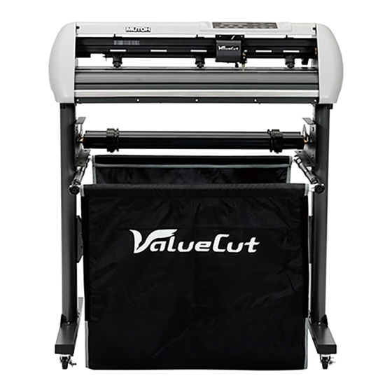
ValueCut User Manual Appearance of ValueCut 1.4.1 The Front View (Figure 1-1) Grid Drums move – the media back and forth during operation. Tool Carriage performs the – cutting with the installed blade and pen with AAS module. Control panel consists of 14 –... -
Page 11: The Whole View
ValueCut User Manual The Whole View of ValueCut (Figure 1-3) 1.4.3 Roll Holder – holds and supplies the roll media for cutting. Roll Holder Guide Bushes serve to – keep the roll media in place when media is pulled from the roll. Roll Holder Support supports... -
Page 12: The Left-Hand Side
ValueCut User Manual 1.4 4 The Left-hand Side (Figure 1-4) Figure 1-4 Power Switch – On when switches to [I]; Off to [O] Fuse – 3 Amp. AC Power Connector – used to insert the AC power cord. 1.4.5 The Right-hand Side (Figure 1-5) Serial Interface Connector (RS232C) –... -
Page 13: Installation
ValueCut User Manual 2. Installation Precaution Please read the following information carefully before you start installation. Note: Make sure the power switch is off before installing the cutting plotter. Carefully handle the cutter to prevent any injuries. Choosing a proper place before setting up the cutting plotter Before installing your cutting plotter, select a suitable location, which meets the following conditions. -
Page 14: Stand & Flexible Media Support System
ValueCut User Manual Stand & Flexible Media Support System (for VC-1300/1800) Step 1 Please examine supplied items in the accessory box of stand carton: 2 piece of T-shape stand 1 piece of stand beam 18 pieces of M6 screws 1 piece of M5 L-shape hexagon screw driver 1 piece of Installation Guide for Stand Set Step 2 Remove the plotter body and the accessories from the shipped carton. - Page 15 ValueCut User Manual Step 3 Position the stand beam perpendicularly to part and put the screws into the holes and tighten them as Figure 2-2. Then the complete picture of stand will be like Figure 2-1. Step 4 Remove the cutting plotter from the carton. Position your stand under the plotter, and then insert the screws into the holes on plotter’s bottom and tighten them up as shown in Figure 2-3.
- Page 16 ValueCut User Manual Step 5 Insert the roll holder support with the screws into the holes of the stand, and then tighten them up as shown in . You could decide roll holder support’s position by inserting into Figure 2-4 different holes.
- Page 17 ValueCut User Manual Step 7 Lastly, the complete picture will be shown like below. ( Figure 2-6 Figure 2-6 Installation...
-
Page 18: Desktop Flexible Media Support System
ValueCut User Manual Desktop Flexible Media Support System (For VC-600 only) Step 1 Please examine the following items in stand carton’s accessory box: 1 set of Roll Media Flange (2 pieces) 1 set of Roll Holder (2 pieces) 1 set of Roll Holder Guide Bushes (4 pieces) 1 set of Roll Holder Support (2 pieces) 1 set of Desktop Support Bracket (2 pieces) 4 pieces of Plastic Foot... - Page 19 ValueCut User Manual Step 3 Position the Desktop Support Brackets beside the Roll Holder Support and insert M6 screws into the Roll Holder Support and tighten them with M6 L-shape screw driver. (Refer to Figure 2-9 at the left). Step 4 Put the bottom of machine in lateral, and position the Roll Holder Assembly beside the bottom of the machine.
-
Page 20: Installation Of Media Basket System
ValueCut User Manual 2.4 Installation of Media Basket System Step 1 Please examine the supplied items in the accessory box 2 pieces of basket arms 2 pieces of basket rods 1 piece of basket 2 pieces of fixtures (for basket arms) 8 pieces of M3 screws 1 piece of 2mm L-shape hexagon screw driver Step 2... - Page 21 ValueCut User Manual Step 3 Insert the basket rods to the basket holes (See Figure 13) Basket rods Basket Figure 2-13 Step 4 Loosen the basket screws from the basket arms. Position the basket rod in front of the basket arms and insert the basket screws into the holes on the basket rod and tighten them.
- Page 22 ValueCut User Manual Step 5 The complete Media Basket System will be like Figure 2-15. Figure 2-15 Installation 2-10...
-
Page 23: Cutting Pad Installation
ValueCut User Manual 2.5 Cutting Pad Installation 1 piece of cutting pad is included in the accessory pack. Follow the instruction below to install a new cutting pad when the existing pad is worn out. Step 1 Carefully remove the cutting pad from the unit. Figure 2-16 Step 2 Remove the remaining adhesive on the groove with alcohol or cleaning naphtha. - Page 24 ValueCut User Manual Step 3 Attach the new cutting pad to the groove after unrolling it and removing the backing sheet and the installation process is completed. Figure 2-18 Figure 2-19 Installation 2-12...
-
Page 25: Blade Installation
ValueCut User Manual Blade Installation Figure 2-20 is the illustrator of the blade holder. Insert a blade into the bottom of the blade holder and remove the blade by pushing the pin. Make sure that your fingers are away from the blade tip. - Page 26 ValueCut User Manual Step 4 Insert the blade holder into tool carriage. Please note the outward ring of the holder must put into the grooves of carriage firmly (see Figure 2-24), then fasten the case (Figure 25). Figure 2-24 Figure 2-25 Step 5 Use the reversing steps to remove the blade holder.
-
Page 27: Automatic Blade Length Detection
ValueCut User Manual 2.7 Automatic Blade Length Detection Figure 2.-26 is the new blade holder with a scale and the carriage with a mark. This blade holder detects blade length automatically and shows how the knob needs to be turned on the LCM. Scale 1 unit Mark... - Page 28 ValueCut User Manual 4. When blade holder and blade length tests are finished, the screen will show you to what degree (the unit of the value following “CW” or “CCW” is “circle”) and in which direction [CW (clockwise) or CCW (counterclockwise)] you should turn the adjustment knob. EG, Turn CW 5 is telling you that you should turn the knob for 5 units clock-wisely (Figure 2-28, Figure 2-29).
-
Page 29: Cable Connections
ValueCut User Manual Cable Connection The cutting plotter communicates with a computer through a USB (Universal Serial Bus), Parallel port (Centronics), or a Serial port (RS-232C). This chapter shows you how to connect the cutting plotter to a host computer and how to set up the computer/cutting plotter interconnection. Note: When USB connection is enabled, both parallel port and serial port will be disabled automatically. - Page 30 ValueCut User Manual Step 1: Connecting your Mutoh cutter 1. Turn on the machine. 2. Connect the USB connector to the machine and then USB driver will installed automatically. It will take a few minutes to find the device. Please DO NOT disconnect the USB cable until the installation has completed.
- Page 31 ValueCut User Manual (3) Click “Next” to start the driver installation. (4) The installation will take a few minutes to complete and you will see a message below and click on “OK” upon completion. Enjoy your Mutoh cutter! Installation 2-19...
-
Page 32: Driver Un-Installation
ValueCut User Manual Note: (1) If the driver is being installed for a second time, the user will be prompted as to whether a second copy of the driver installation is required. 2.8.3 Driver Un-installation You have to remove previous version driver installed on your PC system completely before you can install the latest version successfully. - Page 33 ValueCut User Manual 3. Select “Driver” page Select ValueCut-1300 and click on “Remove”. Installation 2-21...
- Page 34 ValueCut User Manual Click on “OK” Click on “Yes” The driver installed on PC is completely removed. Installation 2-22...
-
Page 35: Interface
ValueCut User Manual 2.8.3 RS-232 Interface Connecting to the RS-232 (Serial) Port 1. For IBM PC, PS/2 users or compatibles, connect the RS-232C cable to the serial connector of the assigned serial port (COM1 or COM2) of your host computer. 2. -
Page 36: The Control Panel
DATA CLEAR CUT TEST PAUSE / RESUME ENTER LINE < LCD Control Panel on ValueCut series > Function LCD Screen To display functions and error messages. Power LED To indicate the power status ( light up: power on; light off: power off ) 4 Arrow Keys To move position, select function, or change setting. -
Page 37: Menu In On-Line Mode
ValueCut User Manual Menu in On-line Mode Power On ValueCut in processing ValueCut Cutter LCM Version- - - ValueCut Firmware: Copyright: Place Media And Then Lower Down The Lever Roll Edge Single to select Sizing Media Width Lever Up To Abort Sizing Media Length Lever Up To Abort Top menu... -
Page 38: Menu In Off-Line Mode
ValueCut User Manual Menu in Off-line Mode Press [ON/OFF LINE] to switch to the offline mode Offline For System Setup Force:80 gf [ FORCE] 5~600 with an increment of 5(gram force) OK:ENTER [ OFFSET ] Offset: 0.275 mm 0.000~1.000 with an increment of 0.025(mm) OK:ENTER [ DATA CLEAR ] Clear Data Memory... - Page 39 ValueCut User Manual Offline For System Setup 1S:72 F:80 O:0.275 M to select from 1S to 4S; [ENTER] to adjust the Select: OK:ENTER parameters Save parameter Select: OK:ENTER [TOOL SELECT ] Restore default Select: OK:ENTER Panel Setup Select: OK:ENTER Pouncing 0 mm Select: OK:ENTER...
-
Page 40: Menu Items
ValueCut User Manual Menu Items Below describes the functions of menu items Menu or Key Function Setting Default --- Media sizing --- Place Media To instruct the user to lower the lever after the material is And Then loaded. Lower Down When the medium is loaded, the user will be requested to The Lever lower the lever;... - Page 41 ValueCut User Manual Up Speed To set or modify tool up speed at horizontal moving. 3~153cm/sec; 72cm/sec 3cm/sec per step Cutting Quality To set or modify cutting quality. Draft, Fair, Normal While cutting small letter, set as “Small letter”. Normal, Fine, While cutting in high speed, set as “Draft”.
- Page 42 ValueCut User Manual confirm. Set Smoothing To enable smooth-cutting function. Enable This function aims to make connections smoother and is suggested to be disabled when cutting small-sized images or characters Over Cut To generate an overcut to facilitate weeding. 0.00mm-1.00mm 0.00mm This function mainly applies to thick materials, aiming to 0.05mm/per step...
- Page 43 ValueCut User Manual 9600, n, 8, 1, p 9600pbs, 8 Bits with NO Parity 9600, o, 8, 1, p 9600pbs, 8 Bits with ODD Parity 9600, e, 8, 1, p 9600pbs, 8 Bits with EVEN Parity 19200, n, 7, 1, p 19200pbs, 7 Bits with NO Parity 19200, o, 7, 1, p 19200pbs, 7 Bits with ODD Parity...
-
Page 44: Operation
ValueCut User Manual 4. Operation Media Loading 4.1.1 Loading the Sheet Media To load the media properly, please follow the procedures listed below: Step 1 Use the lever on the upper right side of the cutting plotter to raise or lower down pinch rollers. Pull the lever forward until it makes a clicking sound then the pinch rollers are raised ( Figure Lever... - Page 45 ValueCut User Manual Step 3 Then move the pinch rollers manually to the proper position. Be sure the pinch rollers must be positioned above the grid drum. The white marks on the top trail will remind you where the grid drums are (Figure 4-3).
-
Page 46: Loading The Roll Media
ValueCut User Manual Note: Please pull up the bottom of all pinch rollers (Figure 4-5) before the lever is pushed backwards to ensure accurate media width detection. Pull up bottom to release grip ENABLE Figure 4-5 4.1.2 Loading the Roll Media Step 1 Put the roll media guide bushes on two roll holders (Figure 4-6). - Page 47 ValueCut User Manual Step 2 -- Option A (Recommended) Insert the two roll holders into the roll media support set then place the roll media directly between the two roll holders ( Figure 4-7 Figure 4-7 -- Option B (Use the media flanges) Insert a roll media flange at the end of each roll media and tighten the thumbscrew until the roll Figure 4-8...
- Page 48 ValueCut User Manual Figure 4-10 Figure 4-11 Step 4 Turn the roll downward to make an equal tension across the media (Figure 4-11) Step 5 Move the pinch rollers to the appraise location and note that the pinch rollers must be positioned above the grid drums.
-
Page 49: Tracking Performance
ValueCut User Manual Tracking Performance In order to achieve the best tracking performance for a long plot, we recommend some significant media loading procedures described as follows: If the media length is less than 4 meters, leave the margin of 0.5mm—25mm in the left and right edges of the media (Figure 4-12). -
Page 50: Cutting Force And Offset Adjustment
ValueCut User Manual Cutting Force and Offset Adjustment Before sending your designs for cutting, you may perform a “cut test” to generate satisfactory cutting results. The “Cut Test” should be repeated until the appropriate cutting conditions for the media are discovered. After sizing the media, press [CUT TEST] button to select the “square cut”, and press [ENTER KEY] to confirm. -
Page 51: How To Cut 3Mm Letter
ValueCut User Manual How to Cut 3mm Letters To obtain good quality output, narrow media is recommended. However, if wide media is used, you should: Position two pinch rollers as close as possible to both edges of the cutting area. Make sure the loaded media is held flat with equal tension across the platen. -
Page 52: When Completing The Cutting Job
ValueCut User Manual Then turn the roll downward to make an equal tension across the media (See Figure 4-16) Make sure that the media tension is equally distributed from left to right. If the media is not tight enough against the platen, it will cause tracking problems. -
Page 53: Option Page
ValueCut User Manual 4.7 ValueCut series Print Driver setting 4.7.1 ValueCut series Print Driver setting > Option Page Figure 4-18 Setting: You can adjust the following settings, depending on your application or results you would like to achieve. Quality: [Slower speeds / higher quality - Faster speeds / lower quality] The Cutting Quality setting function allows you to adjust and balance vector mode’s quality and... - Page 54 ValueCut User Manual Use Plotter Setting: The parameter settings will be set according to those set from the control panel. Back to home: The carriage will return to the original position when this option is selected. Vector Function Normal: This is the default Vector Function setting. The cutting order depends on the order of the graphics created in the application software.
- Page 55 SAVE: This function will save current print driver parameter settings to a file under the specified location on your computer. (Saved parameter setting files will be tagged with the ValueCut series extension) • LOAD: This function allows you to load previously saved print driver parameters.
- Page 56 ValueCut User Manual 4.7.2 ValueCut series Print Driver setting > Pen Page The ValueCut series incorporates the use of 16 different colors to represent 16 different parameter settings including cutting speed, force and blade offset settings when cutting. These colors are referred to as “Pens”. Think of each pen as a designated cutter setting, rather than as a color.
- Page 57 ValueCut User Manual Figure 4-21 Note: The ValueCut series print driver cannot store more than 16 pen colors or different cutter parameter settings per file. Speed (Pen Page) [DEFAULT SETTING: 72cm/sec] The speed slider controls the cutter’s cutting speed during operation with a range setting from 3 – 153cm/sec. The ValueCut series maximum cutting speed is 153 cm (60 inches) per second.
- Page 58 ValueCut User Manual Figure 4-23 Figure 4-22 You can adjust the parameter such as force and length in both Pen No.1 and Pen No. 1* as you need. For example: Figure 4-24 Pen No.1*: Cutting through the backing of the material Pen No.1: Cutting through the vinyl only Operation 4-15...
- Page 59 ValueCut User Manual Sticker Figure 4-25 Operation 4-16...
-
Page 60: Valuecut Print Driver Setting
Y value represents the width. The paper size should be set as the same as your image so you can get a better cutting quality. Unit (Paper Page) [DEFAULT SETTING: Metric (mm)] Here you can set your preferred measurement standard in which you would like use with the VALUECUT series print driver. You can choose between metric or imperial standards. Operation... -
Page 61: Accu-Aligning System
ValueCut User Manual Chapter 5 Accu-Aligning System Introduction The ValueCut series cutting plotters feature a standard Accu-Aligning System (AAS II) to guarantee precise contour cutting quality by detecting the registration marks printed around the graphic. Notice Avoid any kind of light source horizontally illuminating the AAS module. -
Page 62: Calibrating The System
ValueCut User Manual AAS Calibrating the System The AAS system has one calibration procedures to ensure maximum accuracy of AAS operation. To operate the AAS you need to learn about the method of media feeding firstly. (Refer to 4.1 Media Loading.) 5.2.1 Media Calibration Media Calibration is to ensure the sensor being able to recognize the registration marks. -
Page 63: Aas Ii On Valuecut
CorelDraw plug-in. Hand-made marks or drawings won’t be reorganized by Mutoh cutting plotters. For more details about registration mark setting in cutting software, please refer to ‘Appendix A-4: CorelDraw Plug-In Instruction”. - Page 64 ValueCut User Manual High Precision Long Picture Cutting ValueCut performs segmental cutting to enhance output qualities. The object will be output following the Data Block pattern based on the Segmental Positioning parameters. Cutting sequence: Date Block1-> Date Block2-> Date Block3- >Date Block4 3.
-
Page 65: Automatic Distinction Of The Plot Direction
ValueCut User Manual 5.2.4 Automatic Distinction of the Plot Direction For the convenience of users, ValueCut automatically detects the feeding direction of the material when performing contour cutting. Figure 5-1 shows the Registration Mark detection sequence when the material is fed in the standard way (1->2->3->4) while Figure 5-2 is how ValueCut detects registration marks (3->4->1->2) when the material is reversely fed. - Page 66 ValueCut User Manual AAS II_X_Y_Offset_Caberation_600_600 .eps (Default setting, it is recommended for testing) Print out the testing graphic. ( Please use high precision printer) Load the graphic to ValueCut and sent the file to test the cutting job If there are any adjustments to be made, you can change the offset value by following the steps: Measure the offset values from the printed line and the actual cutting line.
-
Page 67: Contour Cutting
ValueCut User Manual Note: Before adjusting the AAS II settings, please proceed scaling for width and length. The blade offset value isn’t set for this test graphic, please set it according to the blade you use. If you have any question, please contact us or your local distributor for assistance. Contour Cutting For accurate contour cutting with AAS function, please proceed the following steps: Step 1 Creating Graphics... - Page 68 ValueCut User Manual Step 2 Placing the Registration Marks The AAS Layout Instruction: * Auto-detection function on the 1 mark covers the grey area Suggested 30mm margin on both left and right sides of media sheet. Suggested 50-70 mm margin on top and bottom edge of the media sheet to prevent sheets dropping or any error occurred while media sizing.
-
Page 69: Tips For Aas
ValueCut User Manual Step 4 Load the printout onto cutter The Origin Mark is is different from the rest registration marks. Please make sure the media is fed with correct direction. Step 5 Cut the Contour Send out the command from software to perform the contour cutting job. Tips for AAS For getting better results of contour cutting, there are some tips below for your reference. -
Page 70: Maintenance
ValueCut User Manual 6. Maintenance This chapter explains the basic maintenance (i.e. cleaning the cutting plotter) required for the cutting plotter. Except for the procedures mentioned below, all other maintenance must be performed by a qualified service technician. Cleaning the Cutting Plotter Cleaning the machine properly and regularly will ensure optimal performance out of your machine. -
Page 71: Cleaning The Grid Drum
ValueCut User Manual Cleaning the Grid Drum 1. Turn off the cutting plotter, and move the tool carriage away from the area needed to be cleaned. 2. Raise the pinch rollers and move them away from the grid drum for cleaning. 3. -
Page 72: Trouble Shooting
ValueCut User Manual 7. Trouble Shooting This chapter is to help you correct some common problems you may come across. Prior to getting into the details of this chapter, please be sure that your application environment is compatible with the cutting plotter. Note: Before having your cutting plotter serviced, please make sure that the malfunction is in your cutting plotter, not the result of an interface problem or a malfunction in your computer or a... -
Page 73: Operational Problems
ValueCut User Manual Operational Problems Some mechanical problems or failure during operation will cause some problems. If the problem still exists after the recommended actions have been taken, have your cutting plotter serviced. 7.2.1 LCM Error Messages The error messages shown on the LCM present the problem first, and followed by recommended actions. -
Page 74: Other Operational Problems
ValueCut User Manual 7.2.2 Other operational problems 1. Pinch rollers Note: Never press the top release grip (the release grip is fully pressed when a clip sound is heard) and pull the bottom release grip at the same time as the pictures shown below. - Page 75 ValueCut User Manual 2. Media is rolled up during the cutting process Step 1 Turn off the cutting plotter Step 2 Move the pinch rollers to the side Step 3 Pull the lever up Step 4 Trim off the rolled up part of the media Step 5 Reload the material 3 The media runs diagonally Step 1 Stop the operation...
-
Page 76: Cutting Plotter/Computer Communication Problems
ValueCut User Manual Cutting Plotter/Computer Communication Problems The messages showed below present problems in relation to cutting plotter/computer communication. Is the connection cable Communication Error connected to the cutting plotter Setup: MISC. key and computer properly? Has the interface setting Refer to Chapter 2 - been done correctly? Connecting your cutting... -
Page 77: Software Problems
ValueCut User Manual Software Problems Check the following first: Does your software package indicate that it will work with your computer and cutting plotter? Does your software support HP-GL and HP-GL/2 drivers? (* check the configuration settings of your software.) Does the cutting plotter interface Most well known cutting softwares match the requirements of your... -
Page 78: Cutting Quality Problems
ValueCut User Manual Cutting Quality Problems Note: The daily maintenance of your cutting plotter is very important. Be sure to clean up the grid drum and pinch rollers regularly for better cutting accuracy and output quality. Is the blade installed correctly and the blade holder fastened securely? Refer to Chapter 2.4 Is the blade dull... -
Page 79: Valuecut Specification
The specification and data sheet may vary with different materials used. In order to obtain the best output quality, please maintain the machine regularly and properly. Mutoh reserves the right to change the specifications at any time without notice. The above listed specification values are effective only when operated with media certified by Mutoh. ValueCut Specification... -
Page 80: Blade Specification
ValueCut User Manual Blade Specification For cutting thick fluorescent and reflective vinyl. Also for cutting detailed work in standard vinyl. The blade is 45° with Red Cap(5-unit package), 0.25 mm offset For cutting reflective vinyl, cardboard, sandblast, flock, and stencil sharp edge. The blade is 60°... - Page 81 ValueCut User Manual About the Tool A generic term referring to the blade that cuts the sheet, the pen that does plotting, and the LED bombsight (option) used for pointing to the reference point. OFFSET is the distance that the blade tip is displaced from the centerline of the blade. Blade Central line Blade tip...
-
Page 82: Consumable And Optional Item List
ValueCut User Manual Consumable and Optional Item List Consumable Items Part Number Item Name Cutting Blade Holder VC-CHD Cutting Blade Red Cap (45° 0.25 )(5pcs/box) VC-CBRE5 Cutting Blade Green Cap (60° 0.5 )(1pcs/box) VC-CBGR1 Cutting Blade Blue Cap (60° 0.25)(1pcs/box) VC-CBBU1 Cutting Blade Black Cap (42°... -
Page 83: Coreldraw Plug-In Instruction
ValueCut User Manual CorelDRAW Plug-In Instruction AASII VBA Installer is applicable for CorelDRAW Version 11, 12, 13, 14, 15, 16. Installation 1. Check the “AAS CorelDraw Installer” folder in ValueCut Installation CD, and double click the “AASIIInstaller.exe” file to run the installation program. 2. - Page 84 ValueCut User Manual User Instructions 1. Run CorelDRAW to edit your graphics and select all images at once when you wish to plot. 2. Select “Tools Visual Basic Play”. CorelDRAW Plug-In...
- Page 85 ValueCut User Manual Visual Basic for Applications Marcos window will pop up. Select Global Macros(AASII_Draw.gms) under the “Macros in” manual, and press “Run”. 3. Click on “Apply” and select whether you would like to add the registration marks by page size or by object.
- Page 86 ValueCut User Manual Add Registration Mark by page size If you tick “Add Registration Mark by page size” as shown in the figure below and click “Apply”, your registration marks will be created automatically. Note: The length setting will be in the range of 5-25mm according to your page size.
- Page 87 ValueCut User Manual Add Registration Mark by Object If you tick “Add Registration Mark by Object”, you will be offered three options of registration marks as shown below. 4-Point Positioning Length: The length of marks Range: 5mm~50mm Optimized Setting: 25mm Thickness: The line thickness of marks Range: 1mm~2mm Optimized Setting: 1mm...
- Page 88 ValueCut User Manual 4-Point Positioning 4-Point Positioning Length: The length of marks Range: 5mm~50mm Optimized Setting: 25mm Thickness: The line thickness of marks Range: 1mm~2mm Optimized Setting: 1mm Margin: The distance between marks and images Range: 0mm~50mm Optimized Setting: 5mm The system will create the 4 marks as shown in the picture below.
- Page 89 ValueCut User Manual Note: The values entered in the “4-Point Positioning” section (length, thickness and margin) will still be applied when you tick “Segmental Positioning” or “Multiple Copies”. 1. To save your materials, in addition to amending object margins, you can also adjust the length of the registration marks (5mm minimum) when you apply 4-Point Positioning (see table 1 for suggestions based on different material sizes).
- Page 90 ValueCut User Manual Segmental Positioning For precise cutting quality, it is suggested to select “Segmental Positioning” when you are working on an extra long or large-sized image to increase cutting accuracy. Segmental Positioning X Step: The distance of intermediate position on the X axis Y Step: The distance of intermediate position on the Y axis Range: 200mm~600mm Optimized Setting: Less than 500mm...
- Page 91 ValueCut User Manual Multiple Copies It is suggested to select “Multiple Copies” when you would like to make several copies of one image on your material to increase cutting accuracy. Multiple Copies No. of X Copies: The numbers of copies on X axis No.
- Page 92 ValueCut User Manual Segmental Positioning will be applied to Multiple Copies when the object to be copied is of large size (with the length or width over 200mm) to increase the accuracy of registration mark detection. Segmental Positioning Please make sure you are happy with the settings for Segmental Positioning as these will be applied to the copies created.
- Page 93 ValueCut User Manual Contour cutting through CorelDraw Step 1: Position the paper with registration marks printed by your printer on the cutter. Step 2: Select “Files Print”. Please note that if you use CorelDraw X5, you must follow the steps below. Click the “color”...
- Page 94 ValueCut User Manual Step 2: Go to the “Layout” page and select Bottom left corner at “Reposition images to”. Step 3: Click “Print”. You can also add a Hot Icon for the AAS II Plug-in Step 1: Select “Tools Customization Commands Macros”. CorelDRAW Plug-In...
- Page 95 ValueCut User Manual Step 2: Choose【_CorelDraw_AASII.Module._AASII】and drag it to the “commands” bar. Step 3: If you want to have a different icon, select “Tools Customization Commands Appearance” to import a graphics for use as the icon. Choose an icon and press OK to complete this setting.
- Page 96 ValueCut User Manual Illustrator Plug-In Instruction Illustrator Plug-In Instruction AASII VBA Installer is applicable for Illustrator Version CS3, CS4, CS5, CS6. Installation 1. Check the “AAS Illustrator Installer” folder in ValueCut Installation CD, and double click the “AASIIInstaller.exe” file to run the installation program. 2.
- Page 97 ValueCut User Manual User Instructions 1) Open Illustrator. 2) Edit your image and create a contour line Note: You must have the line width set as 0.001mm Contour line 3) Click on the image and apply the AAS function (File Scripts _AASII_Plug_In) Illustrator Plug-In...
- Page 98 ValueCut User Manual 4) Select the registration marks needed 5) Three types of registration marks are introduced here: 4-Point Positioning, Segmental Positioning and Multiple Copies. Illustrator Plug-In...
- Page 99 ValueCut User Manual Note: The values entered in the “4-Point Positioning” section (length, thickness and margin) will still be applied when you tick “Segmental Positioning” or “Multiple Copies”. 6) Confirm the registration marks (the 4-Point Position mark is used as an illustration in the following steps).
- Page 100 ValueCut User Manual 7) Click on the blank area on the page and then click “Document Setup”. 8) Hit “Edit Artboards” Note: Keep all Bleed settings as zero when performing segmental cutting to ensure accurate output. Illustrator Plug-In...
- Page 101 ValueCut User Manual 9) Click on “Presets → Fit Artboard to Artwork bounds”. 10) Please move your mouse to the tool bar on the left when step 10) is finished and then click “Selection Tool”. Illustrator Plug-In...
- Page 102 ValueCut User Manual 11) This will take you back to the edit mode. 12) Print out the file with the contour line and the registration marks. 13) Place the printed file on the cutter, lower the pinch rollers and then position the carriage at the origin of the registration marks.
- Page 103 ValueCut User Manual 15) Select the cutter model, position the object in the bottom left corner and then click “Print”. 16) Your job is now completed. Illustrator Plug-In...
- Page 104 ValueCut User Manual Three types of registration marks 4-Point Positioning 4-Point Positioning Length: The length of marks Range: 5mm~50mm Optimized Setting: 25mm Thickness: The line thickness of marks Range: 1mm~2mm Optimized Setting: 1mm Margin: The distance between marks and images Range: 0mm~50mm Optimized Setting: 5mm The system will create the 4 marks as shown in the picture below.
- Page 105 ValueCut User Manual Note: The values entered in the “4-Point Positioning” section (length, thickness and margin) will still be applied when you tick “Segmental Positioning” or “Multiple Copies”. 1. To save your materials, in addition to amending object margins, you can also adjust the length of the registration marks (5mm minimum) when you apply 4-Point Positioning (see table 1 for suggestions based on different material sizes).
- Page 106 ValueCut User Manual Segmental Positioning For precise cutting quality, it is suggested to select “Segmental Positioning” when you are working on an extra long or large-sized image to increase cutting accuracy. Segmental Positioning X Step: The distance of intermediate position on the X axis Y Step: The distance of intermediate position on the Y axis...
- Page 107 ValueCut User Manual Multiple Copies It is suggested to select “Multiple Copies” when you would like to make several copies of one image on your material to increase cutting accuracy. Multiple Copies No. of X Copies: The numbers of copies on X axis No.
- Page 108 ValueCut User Manual Illustrator Plug-In...
Need help?
Do you have a question about the ValueCut Series and is the answer not in the manual?
Questions and answers