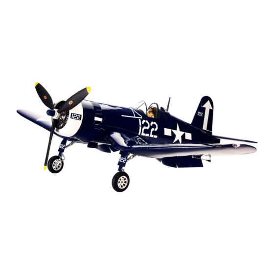
Hangar 9 F4U-1D Corsair 60cc ARF Instruction Manual
Hide thumbs
Also See for F4U-1D Corsair 60cc ARF:
- Assembly manual (64 pages) ,
- Instruction manual (96 pages)
Table of Contents
Advertisement
Quick Links
Advertisement
Table of Contents

Related Manuals for Hangar 9 F4U-1D Corsair 60cc ARF


Summary of Contents for Hangar 9 F4U-1D Corsair 60cc ARF
- Page 1 F4U-1D Corsair 60cc ARF Instruction Manual Bedienungsanleitung...
-
Page 2: Using The Manual
Safety warningS and precautionS Safe operating recommendationS NOTICE All instructions, warranties and other collateral documents are subject to change at the sole discretion of Read and follow all instructions and safety precautions • Inspect your model before every flight to ensure it is Horizon Hobby, Inc. - Page 3 warnungen und Sicherheit- empfehlungen zum Sicheren HINWEIS Svorkehrungen BetrieB Alle Anweisungen, Garantien und anderen zugehörigen Dokumente können im eigenen Ermessen von Horizon Hobby, Inc. jederzeit geändert werden. Die aktuelle Produktliteratur finden Sie auf horizonhobby.com unter der Bitte lesen und befolgen Sie alle Anweisungen und • Überprüfen Sie zur Flugtauglichkeit ihr Modell vor jedem Registerkarte „Support“...
- Page 4 SpecificationS•Spezifikationen Large partS Layout•BauteiLe (ohne kLeinteiLe) 85.5 in (217 cm) 1380 sq in (89 dm2) 70.0 in (177 cm) 28.5–31.0 lb (12.9–14.0 kg) 2-Stroke Gas/Petrol: 50–62cc 2-Takt Benzin: 50-62cc 4-Stroke Gas/Petrol: 57cc 4-Takt Benzin: 57cc 4-Stroke Glow: 77cc 4-Takt Glühzünder: 77cc 6-channel (or greater) with 7-8 servos 6-Kanal (oder größer) mit 7-8 servos Spinner...
- Page 5 repLacement partS•erSatzteiLe requireD raDio equipment•erforDerLiche rc auSrüStung part english deutsch part english deutsch HAN476001 Fuselage with Fin Rumpf m. Seitenleitwerk SPMAR9110 AR9110 9-Channel DSMX PowerSafe Spektrum AR9110 9 Kanal DSM X ® ™ Receiver Empfänger mit Akkuweiche HAN476002 Right Wing Panel with Aileron and Outer Flap Tragfläche rechts m.
- Page 6 Filter mit Gewicht HAN116 Fuel Filler with “T” Fitting and Overflow Fitting Kraftstoffstutzen mit T-Stück und Überlauf HAN116 Fuel Filler with “T” Fitting and Overflow Fitting Hangar 9 Tanknippel mit T-Stück u. Überlauf Fitting ZEN20000 Zenoah ™ Kill Switch Zenoah Kill Schalter...
- Page 7 optionaL gear DoorS (partS LiSteD are SuggeSteD)• requireD tooLS•BenötigteS werkzeug optionaLe fahrwerkStüren (Siehe teiLeempfehLung) english deutsch part english deutsch Box wrench: 17mm Ringschlüssel 17mm SPMSA7010 (4) A7010 Wing Servo Spektrum A7010 Tragflächenservo Clear tape klares Klebeband SPMA3002 (2) Heavy-Duty Servo Extension 9 inch Spektrum Hochleistungs Crimping tool Crimpzange...
- Page 8 requireD tooLS•BenötigteS werkzeug faStenerS•verBinDungSeLemente english deutsch Pliers Zange Flat Washer Lock Nut Razor saw Säge Unterlegscheibe Stopmutter Rotary tool Dremel Ruler Lineal Sanding drum Schleiftrommel Setscrew Hex Nut Madenschraube Sechskantmutter Medium grit sandpaper Schleifpapier mittel Scissors Schere Side cutters Seitenschneider Metal Clevis Button Head Cap Screw Turnbuckle tool...
- Page 9 aSSemBLy SymBoL guiDe•montage SymBoLe Apply threadlock Ensure free rotation Use medium CA Use a pencil Schraubensicherungslack verwenden Rotation sicherstellen Mittelflüssigen Verwenden Sie einen Bleistift Sekundenkleber verwenden Assemble right and left Push tightly Use thin CA Use a felt-tipped pen Links und rechts montieren Fest drücken Dünnflüssigen Verwenden Sie einen Faserstift...
- Page 10 Joining the wing paneLS•verkLeBen Der tragfLächen 3 5 1 2 Remove the joiner from the tip panel and slide it into the Separate the tip panel from the center section. Apply a coating center section. It should slide in past the line drawn in the of petroleum jelly to the area around the joiner pocket so when previous step.
- Page 11 7 8 9 aiLeron Servo inStaLLation• einBau der QuerruderServoS 1 Slide the joiner in position. Use isopropyl alcohol and a paper towel to remove the excess epoxy that will flow out when the joiner is slid into the joiner pocket. Separate the tip panels from the center section.
- Page 12 3 5 6 7 M3 x 10 Prepare the aileron servos by installing the grommets and brass eyelets. Also install the Heavy Duty Servo Arms (JRPA215) perpendicular to the servo centerline. Thread a screw into each of the holes in the aileron servo cover mounting holes.
- Page 13 8 aiLeron preparation•querruDervorBereitung 4 1 2 Top• Oberseite M3 x 10 Secure the aileron servo into position using the black M3 x 10 Insert the hinges into the ailerons. Use the depth gauge washer head screws. The arrows indicate the location of the marked with an A to make sure the hinges fit into the aileron.
- Page 14 6 7 8 fLap hinging• anSchlagen der klappen 1 Fit the aileron to the wing. There will be a gap of 1/32 to 1/16 It may be necessary to bevel the inner lip of the wing panel inch (1 to 1.5mm) between the aileron leading edge and wing near the tip if you find the aileron binding.
- Page 15 2 3 4 5 Apply a small amount of petroleum jelly to the flex point of the Insert the hinges into the flap panels until the line drawn in hinge to prevent epoxy from entering the hinge. Draw a line the previous step is aligned with the leading edge of the flap.
- Page 16 6 7 8 9 Check the angle of the hinges in relationship to the flap center The hinges in the center flap will angle inward slightly when line. They will be perpendicular for the inner and outer flaps. installed.
- Page 17 10 11 12 Check the operation of the flap, using care not to move the hinges from their locations. When positioned correctly, you will be able to achieve the throws listed in the Control Throw section of this manual. Prüfen Sie den Weg der Klappen und achten dabei darauf die Scharniere nicht aus ihren Positionen zu bewegen.
- Page 18 13 14 15 Check the alignment of the flaps to the top of the wing. It may be necessary to adjust the position of the holes to correct the alignment of the flap, or to allow the flap to move through its range of motion.
- Page 19 17 fLap Servo inStaLLation•einBau Der kLappenServoS 4 1 3 M3 x 10 Move the string inside the center section so the flap servo can Use a small amount of epoxy to glue the dowel pins into the Thread a screw into each of the flap servo mounting holes.
- Page 20 6 8 9 aiLeron Servo Linkage inStaLLation• einBau der Querruderanlenkung 1 Attach the ball end to the flap servo arm. Connect the ball end to the flap control horns. Adjust the length of the linkage so the flaps are up when the servo is in Setzen Sie den Kugelkopf auf den Klappenservoarm.
- Page 21 3 retract inStaLLation•einBau DeS einziehfahrwerkeS 3 1 2 #8 x 3/4 Connect the clevis to the aileron servo arm. Use the hole that Thread the bolt into the retract strut. A final nut is threaded is 11/16 inch (17mm) from the center of the arm. Slide the against the strut to secure the bolt in position.
- Page 22 4 5 6 7 #8 x 3/4 Fit the retract into the wing. Secure the assembly in the wing. Once the retract has been positioned, remove it from the wing and attach two 18-inch (457mm) pieces of air line to the Setzen Sie das Fahrwerk in die Tragfläche ein und schrauben retract.
- Page 23 8 9 11 12 Slide the air line at the rear of the retract through the pre- Tape the rear air line and a 18-inch (457mm) servo extension Once placed, use a small amount of medium CA to glue the drilled hole in the spar.
- Page 24 LanDing gear Door inStaLLation•einBau Der fahrwerkStüren 5 6 1 3 M2 x 10 Roughen the hinges and covers using coarse grit sandpaper. Tape the cover to the wing using low-tack tape. Use a drill and Clean the area using a paper towel and isopropyl alcohol. Use 1/32-inch (1mm) drill bit to drill the six holes to mount the Locate the stops for the retract cover.
- Page 25 7 8 10 12 Lower the gear into the wing. Guide the door into position, With the cover and door removed, remove the clear tape. Cut the rubber band. Use medium CA to glue the rubber band checking the alignment to the cover.
- Page 26 14 16 (optionaL•optionaL) 17 Complete the retract installation by placing the connectors and t-fittings on the air lines running to the retracts. Use a 1-inch (25mm) piece of air line between the connectors and Tape the gear door to the wing using low-tack tape. Use a drill t-fittings.
- Page 27 receiver Battery inStaLLation•einBau DeS empfängerakkuS 5 6 1 3 M3 x 10 Route the leads from the batteries to the receiver inside the fuselage. Connect 12-inch (305mm) battery extensions to the Place a receiver battery into the compartment, routing the batteries, routing the extensions through the formers toward Thread a black screw into each of the holes to cut threads leads through the openings and into the fuselage.
-
Page 28: Rudder And Elevator Servo Installation
rudder and elevator Servo air tank anD receiver inStaLLation•einBau DeS DruckLufttank unD DeS empfängerS inStaLLation• 1 3 4 einBau von höhen unD SeitenruderServo 1 4-40 x 1/2-inch Prepare the air tank by attaching a 2-inch (51mm) piece of air line to the tank. - Page 29 5 6 7a (air retract inStaLLation• 7B (eLectric retract einBau deS inStaLLation• pneumatikfahrwerkS) einBau deS elektriSchen fahrwerkeS) Connect the leads for the rudder and elevator servos. Connect a 6-inch (152mm) lead for the aileron and flap servos. A 12-inch (305mm) lead will be required for connection to the Remove the covering from the side of the fuselage for the Mount the receiver on a piece of 1/4-inch (6mm) foam in the...
- Page 30 8 9 ruDDer inStaLLation•einBau DeS SeitenruDerS 1 2 Position the hinge perpendicular to the hinge line. Check that it can move freely. Richten Sie das Scharnier rechtwinklig zur Scharnierlinie aus. Prüfen Sie dass es sich frei bewegen kann. ...
- Page 31 4 5 ruDDer Linkage inStaLLation•einBau Der ruDeranLenkung 1 2 Fit the rudder to the fin, guiding the torque rod into the 8-32 x 1 inch fuselage. Make sure the rudder torque rod is inserted through Slide the collar on the rudder torque rod. Tighten the bolt the hole in the former for support.
- Page 32 4 5 7 StaBiLizer inStaLLation• einBau DeS höhenLeitwerkS 1 Center the rudder servo using the radio system. Place the Thread the ball end on the rudder pushrod. With the rudder large servo arm (not included, JRPA215) on the rudder servo servo centered, place the horn on the rudder servo.
- Page 33 2 3 4 6 Slide the stabilizer on the tubes. The stabilizer will fit tightly Remove the covering from the fuselage where the stabilizer against the fuselage. Install both stabilizer halves at this fits against the fuselage. Leave a 1/8-inch (3mm) lip so the time.
- Page 34 8 9 eLevator inStaLLation•einBau DeS höhenruDerS 1 Lightly sand the tubes using coarse sandpaper. Use isopropyl alcohol and a paper towel to clean the stabilizer tubes, removing any oils or debris from the tubes. Schleifen Sie die Verbinder an und reinigen diese Alkohol und Papiertüchern.
- Page 35 2 4 5 6 Position the hinge perpendicular to the hinge line. Check that Thread the control horn on the elevator torque rod. Note that Check the fit of the elevator in place to the stabilizer. Also Center the elevator servo using the radio system.
- Page 36 8 9 10 12 Thread the 45 -inch (1150mm) elevator pushrod 12 to 14 With the elevator and elevator servo centered, mark the Check the alignment of the elevator when the ball link is turns into the ball end. pushrod at the edge of the ball link.
- Page 37 13 pneumatic retract Servo inStaLLation•einBau DeS pneumatiSchen einziehfahrwerkServoS 1 3 4 #2 x 1/2 Thread a screw into each of the holes to cut threads into the surrounding wood. Remove the screw before proceeding. Apply Place the retract servo in the servo mount. Mark the locations Use a pin vise and 1/16-inch (1.5mm) drill bit to drill Assemble the pushrod with Z bend to the clevis and connect a small amount of thin CA to harden the threads made in the...
- Page 38 5 6 8 taiL wheeL inStaLLation• einBau deS SpornradeS 1 Prepare the connectors for the retract valve by attaching a 6-inch (152mm) piece of tubing to the connectors. Make sure to match the ail line fittings and color coding to match the air Lower the retract servo assembly into the fuselage.
- Page 39 2 4 6 8 Cut the heat shrink tubing into four 30mm pieces. Connect the clevises from the cables to the steering arm of the trail wheel retract assembly in the middle hole. Slide the Schneiden Sie den Schrumpfschlauch in vier 30mm lange silicone retainers over the forks of the clevis to secure their Cut the tail wheel cable into two equal lengths.
- Page 40 10 11 12 14 4-40 x 1/2-inch Thread the actuator pushrod into the retract actuator. Remove the pin and clip from the actuator and actuator While holding the actuator tightly against the former in the mount. Secure the mount to the former using the screws fuselage, check the operation of the tail wheel retract.
- Page 41 16 17 18 (optionaL•optionaL) ScaLe exhauSt inStaLLation• einBau der Scale auSpuffanlage 1 M2 x 8 M2 x 8 Tape the tail gear cover to the fuselage using low-tack tape. Carefully trim the tail gear door to fit the tail wheel retract. Use a drill and 1/32-inch (1mm) drill bit to drill the four holes Make sure the retract can move without hitting the door.
- Page 42 2 engine inStaLLation (g62)•motoreinBau (g62) 1 3 5 M3 x 10 Use a rotary tool and sanding drum to enlarge the opening in Examine the fuel tank to determine where the fuel lines attach Thread the screw into the hole to cut threads in the the fuselage if you are using the optional spring starter on inside the tank.
- Page 43 7 9 11 12 1/4-20 x 1 inch Secure the fuel tank inside the fuselage using the tie wraps. Make sure the vent faces toward the top of the fuselage when the tank is installed. Install the carburetor adapter and arm on the engine. Trim the Attach the engine to the firewall.
- Page 44 13 14 15 17 Route the vent line from the fuel tank to the bottom of the Trim a mount for the engine kill switch using a spare engine fuselage. A fuel dot was mounted in the scale exhaust for the mounting template.
- Page 45 18a (evoLution 777) 18B (Saito fg57) cowLing inStaLLation•montage Der motorhauBe 1 3 Locate the cowling. Note that the top of the cowling is Cut and trim the forward portion of the engine to fit over the indented, while the bottom is completely round.
- Page 46 4 5 7 cockpit interior inStaLLation• einBau deS cockpitinterieurS 1 4-40 x 3/4-inch Glue the scale engine inside the cowling using silicone Secure the propeller to the engine using the recommended adhesive. spinner adapter. Use a box wrench to tighten the propeller bolt.
- Page 47 3 4 5 6 Fit the instrument panel into the cockpit. Use hobby scissors Use a pin vise and 1/8-inch (3mm) drill bit to drill a hole in to trim the panel as necessary. Glue the instrument panel in the cockpit floor for the control stick.
- Page 48 SLiDing canopy inStaLLation•einBau Der cockpitöffnung 4 Î Additional detail can be added to the cockpit using a variety of items including, but not 2 Î The model comes with a sliding canopy. This limited to paint,chalk, pins, etc. Use the following has been tested with all of the suggested motors images to help in detailing the cockpit.
- Page 49 6 8 9 11 Fit the front canopy on the fuselage. Make sure that it Use 5 min epoxy to glue the sliders to the rear canopy. Check Apply one layer of tape toward the front of the rails. The tape fits flush to the rear and the center pins and magnets are to make sure the sliders are still aligned to the marks.
- Page 50 optionaL SoLiD canopy inStaLLation• Scale acceSSorieS 2 4 optionaler einBau der fixen 1 kaBinenhauBe 1 Thread the pitot tube into the blind nut located in the left Fit the guns to the wing. Trim the wing as necessary to fit the wing tip panel.
- Page 51 6 optionaL Lighting•optionaLe BeLeuchtung 5 1 3 Secure the lighting controller inside the fuselage. Connect the controller to an open port on the receiver to power and actuate the lights using the radio system. Connect an 18-inch (457mm) lighting extension to two of the leads from the controller to connect to the extension that will be located in the wing center section.
- Page 52 orDinance inStaLLation•anBau Der auSSenLaSten 4 6 1 3 Use a ruler to connect the lines at the front and rear of the center section. This will be used as a reference when placing Place low-tack tape along the centerline of the center section. the ordinance mounts.
- Page 53 8 10 11 12 M3 x 15 While holding the ruler, mark the location for positioning the Move the pylon, then drill the mounting holes using a drill and Insert an 18-inch (457mm) and 24-inch (609mm) servo Remove the tape from the wing.
- Page 54 14 15 17 18 Draw a centerline on the hardwood mount located in the Attach the release mount to the ordinance using either the ordinance. The mount location can be seen when looking screws provided with the release kit, or using epoxy. carefully at the ordinance.
- Page 55 DecaL inStaLLation• anBringen deS dekorBogen Apply the decals to your model using the image located on the following page of the manual and the box art from your model. Use a spray bottle and a drop of dish washing liquid or glass cleaner sprayed in the location of the decal to allow repositioning of the decal.
-
Page 56: Center Of Gravity
center of gravity der Schwerpunkt An important part of preparing the aircraft for flight is properly balancing the model. Ein sehr wichtiger Teil in der Flugvorbereitung ist es das Flugzeug richtig auszubalancieren. 1. Attach the wing panels to the fuselage. Make sure to connect the leads from the aileron to the appropriate leads from the 1. -
Page 57: Control Throws
control throwS ruDerauSSchLäge 1. Turn on the transmitter and receiver of your model. Check the movement of the rudder using the transmitter. When the stick 1. Schalten Sie den Sender und Empfänger ihres Modells ein. Prüfen Sie die Seitenruderaussschläge mit dem Sender. is moved to the right, the rudder should also move right. -
Page 58: Preflight Checklist
preflight checkliSt vorflugkontrolle daily flight checkS tägLicher fLug check • C harge the transmitter, receiver and motor battery for • L aden Sie den Sender- ,Empfänger- und Zündakku für • C heck the battery voltage of the transmitter battery. Do • Ü berprüfen Sie die Spannung des Senderakkus. Fliegen your airplane. Use the recommended charger supplied Ihr Flugzeug. Verwenden Sie für die RC Anlage bitte not fly below the manufacturer’s recommended voltage. -
Page 59: Limited Warranty
limited warranty what this warranty covers Limitation of Liability inspection or Services non-warranty Service Horizon Hobby, Inc. (“Horizon”) warrants to the original HORIZON SHALL NOT BE LIABLE FOR SPECIAL, INDIRECT, If this Product needs to be inspected or serviced and is Should your service not be covered by warranty, service purchaser that the product purchased (the “Product”) will be INCIDENTAL OR CONSEQUENTIAL DAMAGES, LOSS OF... -
Page 60: Garantie Und Service Informationen
garantie und Service informationen warnung fragen, hilfe und reparaturen kostenpflichtige reparaturen Horizon behält sich vor, alle eingesetzten Komponenten zu prüfen, die in den Garantiefall einbezogen werden können. Ein ferngesteuertes Modell ist kein Spielzeug. Es kann, wenn Die Entscheidung zur Reparatur oder zum Austausch liegt Ihr lokaler Fachhändler und die Verkaufstelle können eine Liegt eine kostenpflichtige Reparatur vor, erstellen wir einen es falsch eingesetzt wird, zu erheblichen Verletzungen bei... -
Page 61: Instructions For Disposal Of Weee By Users In The European Union
warranty anD Service contact information• garantie und Service kontaktinformationen Country of Horizon Hobby Contact Information Address Purchase Horizon Service Center servicecenter.horizonhobby.com/Re- (Repairs and Repair Requests) questForm/ www.quickbase.com/db/ Horizon Product Support United States 4105 Fieldstone Rd bghj7ey8c?a=GenNewRecord (Product Technical Assistance) of America Champaign, Illinois, 61822 USA 888-959-2305 sales@horizonhobby.com... -
Page 62: Ama National Model Aircraft Safety Code
ama national model aircraft Safety code effective January 1, 2013 B. raDio controL (rc) (h) Not operate model aircraft while under the influence of 7. Under no circumstances may a pilot or other person touch alcohol or while using any drug which could adversely affect a model aircraft in flight while it is still under power, except a. - Page 63 inch (28mm)
- Page 64 © 2013 Horizon Hobby, Inc. Hangar 9, DSMX, JR, Evolution, PowerSafe and EC3 are trademarks or registered trademarks of Horizon Hobby, Inc. The Spektrum trademark is used with permission of Bachmann Industries, Inc. Zenoah is a trademark or registered trademark of Husqvarna Zenoah Co. Ltd. Corporation and is used with permission.
Need help?
Do you have a question about the F4U-1D Corsair 60cc ARF and is the answer not in the manual?
Questions and answers