Table of Contents
Advertisement
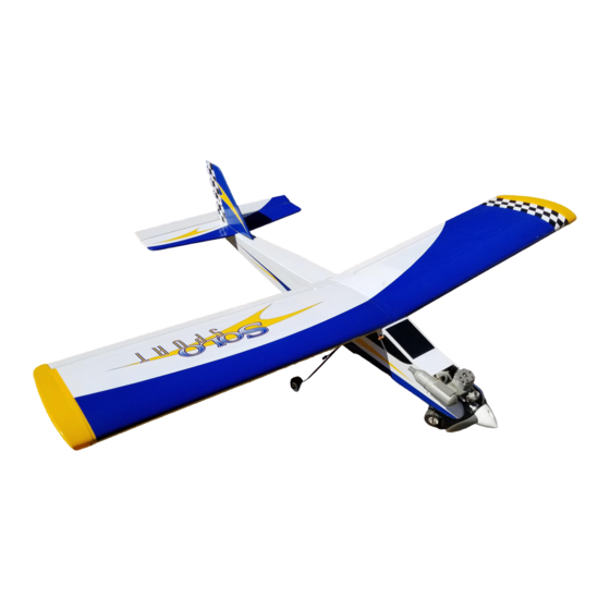
INSTRUCTION MANUAL
• Easy to fly – great for first-time pilots
• Excellent self righting flight characteristics
• 90% pre-built and covered in pre-printed, heat shrinkable PVC
• All hardware included
• Three trim schemes to choose from
90
%
PRE-BUILT
ALMOST READY-TO-FLY
Specifications
Wingspan:
. . . . . . . . . . . . . . . . . . . . . . . . . . . . . . . . . . . . .
Length:
. . . . . . . . . . . . . . . . . . . . . . . . . . . . . . . . .
Wing Area:
. . . . . . . . . . . . . . . . . . . . . . . . . . . . . . . . .
Weight (Approx.):
. . . . . . . . . . . . . . . . . . .
Recommended Engines:
.40 –.48 2-cycle
. . . .
.45 –.56 4-cycle
WE GET PEOPLE FLYING
C O L L E C T I O N
Sport
''
62
''
45
1
/
sq.
2
720 in.
6-6
1
/
lbs.
4
TM
TM
Star
Strike
Advertisement
Table of Contents

Subscribe to Our Youtube Channel
Related Manuals for Hangar 9 Hangar 9 Solo


Summary of Contents for Hangar 9 Hangar 9 Solo
-
Page 1: Instruction Manual
WE GET PEOPLE FLYING C O L L E C T I O N INSTRUCTION MANUAL • Easy to fly – great for first-time pilots • Excellent self righting flight characteristics • 90% pre-built and covered in pre-printed, heat shrinkable PVC •... -
Page 2: Table Of Contents
Table of Contents Introduction Radio System Setup Additional Equipment Required Additional Tools and Supplies Required Contents of Kit Field Equipment Required Optional Field Equipment Section 1: Assembling the Wings Section 2: Joining the Wing Halves Section 3: Installing the Aileron Servo Tray Section 4: Assembling the Fuselage Section 5: Installing the Wing Dowels Section 6: Hinging the Vertical and Horizontal Stabilizers... -
Page 3: Introduction
Introduction Congratulations on your purchase of a Hangar 9 Solo. This trainer aircraft has a choice of unique finishes that will set it apart from the general trainer type of aircraft. It’s an ideal trainer, as well as a good choice for a second aircraft for modelers who demand a good looking model that can be built in a few short evenings. -
Page 4: Additional Tools And Supplies Required
Additional Tools and Supplies Required (not supplied) Adhesives CA (cyanoacrylate) glue (thick) 6-minute epoxy 30-minute epoxy Thread Lock (e.g., Blue Locktite 242) Tools Drill Drill bits: 1/16′′, 5/32′′ Phillips screwdrivers Z-bend pliers Pliers Small round file Razor saw Moto-Tool with sanding drum Wax paper Mixing stick Epoxy brush... -
Page 5: Contents Of Kit
Contents of Kit Covered Parts Others A. Fuselage 1. Pushrod and Accessories B. Left wing half with aileron 2. 1/8′′plywood die-cut parts C. Right wing half with aileron 3. Main landing gear D. Vertical stabilizer with rudder 4. Nose landing gear E. -
Page 6: Field Equipment Required
Field Equipment Required Propeller Glow Plug Wrench Airplane Fuel MAS1060 HAN2510 HAN3110 Glow Plug Glow Plug Igniter with Charger Manual Fuel Pump HAN3000/3005 HAN118 MCD101 The Hangar 9 Skypack includes everything you need to get your airplane into the air. If you purchase the Skypack, you do not need to purchase the additional materials above (except rubber bands). -
Page 7: Optional Field Equipment
Optional Field Equipment Field Box Cleaner & Towels 4-Way Wrench HAN130/131 DUB701 Misc. Tools After-Run Fuel Extra Glow Plugs HAN3100 HAN 3000/3005 12V Sealed Battery 12V Starter Power Panel HAN102 HAN104 HAN106 The HANSTART Start-up Field Pack includes: • Flight tote •... -
Page 8: Section 1: Assembling The Wings
Section 1: Assembling the Wings Parts Needed Tools and Adhesives Needed • Right wing panel with aileron and hinges • 30-minute epoxy • Left wing panel with aileron and hinges • Mixing stick/epoxy brush • Paper towels • Rubbing alcohol •... - Page 9 Section 1: Assembling the Wings CONTINUED 6. Mix a small amount, approximately 1/4 oz., of 30-minute 8. Carefully wipe off any excess epoxy using a paper towel and epoxy to be used for installing the aileron onto the wing half. rubbing alcohol.
-
Page 10: Section 2: Joining The Wing Halves
Section 2: Joining the Wing Halves Parts Needed Tools and Adhesives Needed • Right wing panel from Section One • 6-minute epoxy • Left wing panel from Section One • 30-minute epoxy • Three plywood wing joiners • Clips (e.g., clothespins, binder clips (4)) •... - Page 11 Section 2: Joining the Wing Halves CONTINUED ′′, very lightly sand the wing rib on just 5. Allow the epoxy to cure completely before removing the measurement is not 4 ⁄ clamps. one of the wing panels. Refit the wings and re-check the angle. 6.
- Page 12 Section 2: Joining the Wing Halves CONTINUED 13. Coat one half of the dihedral brace with epoxy up to the 15. Smear epoxy on all sides of the exposed area of the dihedral center line drawn in Step 6. Install the epoxy-coated side of the brace and uniformly coat both wing roots with epoxy.
- Page 13 Section 2: Joining the Wing Halves CONTINUED 16. Carefully slide the two wing halves together, ensuring they Note: It’s a good idea to place a sheet of waxed paper under are accurately aligned. Firmly press the two wing halves the center joint of the wing so any excess epoxy together, allowing the excess epoxy to run out.
-
Page 14: Section 3: Installing The Aileron Servo Tray
Section 3: Installing the Aileron Servo Tray Parts Needed Tools and Adhesives Needed • Wing • Masking tape • Plywood aileron tray • Hobby knife • Plywood aileron tray support (2) • Felt tipped pen • Aileron servo • 6-minute epoxy •... - Page 15 Section 3: Installing the Aileron Servo Tray CONTINUED 7. With a sharp hobby knife, carefully cut a 1/8′′ wide slot 10. Trial fit the aileron servo into the servo tray, as well as into which is 1-5/8′′ in length through both the covering and the the hole which was cut in the previous step.
- Page 16 Section 3: Installing the Aileron Servo Tray CONTINUED 11. Mix a small amount, approximately 1/4 oz., of 6-minute epoxy and apply it to one of the aileron servo supports between the two tabs. Position the aileron servo tray in place as shown and lightly spread epoxy along the joint between the aileron servo tray and the aileron servo support.
- Page 17 Section 3: Installing the Aileron Servo Tray CONTINUED 13. After the epoxy has cured, mix a small amount, 14. Locate the wing center tape and remove the adhesive approximately 1/4 oz., of 6-minute epoxy to glue the servo tray backing. Starting at the rear of the aileron servo tray, wrap the into the wing.
-
Page 18: Section 4: Assembling The Fuselage
Section 4: Assembling the Fuselage Parts Needed Tools and Adhesives Needed • Fuselage • Hobby knife or file • Plywood servo tray • Epoxy brush • 30-minute epoxy • Rubbing alcohol • Paper towel 1. Remove the plywood servo tray from the die-cut plywood 3. - Page 19 Section 4: Assembling the Fuselage CONTINUED 4. Mix a small amount, approximately 1/8 oz., of 30-Minute Epoxy. Using an epoxy brush, apply epoxy to the servo tray in the areas that will come in contact with the servo tray support and the fuselage sides.
-
Page 20: Section 5: Installing The Wing Dowels
Section 5: Installing the Wing Dowels Parts Needed Tools and Adhesives Needed • Fuselage • 6-minute epoxy ′′) (2) • Wing dowels (5 • Epoxy brush • Hobby knife • Paper towels • Rubbing alcohol 1. Locate the four pre-drilled wing dowel holes, two on either 2. -
Page 21: Section 6: Hinging The Vertical And Horizontal Stabilizers
Section 6: Hinging the Vertical and Horizontal Stabilizers Parts Needed Tools and Adhesives Needed • Horizontal stabilizer with elevator • 30-minute epoxy • Vertical stabilizer with rudder • Mixing stick • Epoxy brush • Paper towels • Rubbing alcohol • Sandpaper (medium) 1. - Page 22 Section 6: Hinging the Vertical and Horizontal Stabilizers CONTINUED 5. Carefully wipe away any excess epoxy using a paper towel 6. Repeat this procedure to install the elevator to the horizontal and rubbing alcohol. stabilizer.
-
Page 23: Section 7: Installing The Tail
Section 7: Installing the Tail Parts Needed Tools and Adhesives Needed • Fuselage • 30-minute epoxy • Wing • Hobby knife with #11 blade • Horizontal stabilizer with elevator • Straight edge • Vertical stabilizer with rudder • Pencil • Felt tipped pen •... - Page 24 Section 7: Installing the Tail CONTINUED 4. Install the wing, then check the alignment of the horizontal 7. Remove the horizontal stabilizer from the fuselage. Using a stabilizer by measuring from a fixed point on the wing (tip of straight edge make sure the lines drawn are straight. Using a wing) to the tip of the elevator.
- Page 25 Section 7: Installing the Tail CONTINUED 9. Install the horizontal stabilizer onto the fuselage and adjust 13. Remove the vertical stabilizer from the fuselage. Using a the alignment as described in Step 4 and 5. sharp hobby knife, carefully cut away the covering below the lines drawn in the previous step.
- Page 26 Section 7: Installing the Tail CONTINUED 15. Insert the vertical stabilizer into the fuselage, ensuring that 16. Secure the vertical stabilizer in place using masking tape it’s seated properly on the horizontal stabilizer. Precisely align and allow the epoxy to cure completely. the vertical stabilizer as described in Step 11 of this section.
-
Page 27: Section 8: Installing The Control Horns
Section 8: Installing the Control Horns Parts Needed Tools and Adhesives Needed • Control horns (2) • Drill • Control horn back plate (2) • 1/16′′ drill bit • Control horn screws (4) • Felt tipped pen • Fuselage (with vertical and horizontal stabilizers) •... - Page 28 Section 8: Installing the Control Horns CONTINUED 4. Remove the control horn and drill two 1/16′′ holes through 7. Center the control horn over the mark made in the previous the elevator as shown. step, making sure it’s centered over the hinge line. Again, mark the location of the control horn mounting hole positions when you’re satisfied with the alignment.
-
Page 29: Section 9: Assembling And Installing The Fuel Tank
Section 9: Assembling and Installing the Fuel Tank Parts Needed Tools and Adhesives Needed • Fuel tank • Phillips screwdriver (medium) • Fuel tubing (not supplied) • Hobby knife • Fuel clunk • Masking tape (optional) • Aluminum tube, short (pickup) •... - Page 30 Section 9: Assembling and Installing the Fuel Tank CONTINUED 4. Slide this tube into the remaining hole in the black rubber 6. Locate the silicone fuel tubing and the metal clunk. Insert the stopper. fuel clunk into one end of the fuel tubing. This assembly will be used for the fuel pickup inside the fuel tank.
- Page 31 Section 9: Assembling and Installing the Fuel Tank CONTINUED Note: It’s important to make sure the fuel tank clunk doesn’t 12. Slide the fuel tubing of the fuel tank over the two pieces of touch the rear of the fuel tank. If it does, simply cut a music wire in the fuselage small portion of the silicone fuel tubing until the clunk no longer reaches the rear of the tank.
-
Page 32: Section 10: Installing The Main Landing Gear
Section 10: Installing the Main Landing Gear Parts Needed Tools and Adhesives Needed • Main landing gear (2) • Epoxy brush • Landing gear straps (2) • Felt tipped pen • 3mm self tapping screws (4) • 6-minute epoxy • Wheels (2) •... - Page 33 Section 10: Installing the Main Landing Gear CONTINUED 5. Remove the landing gear straps and landing gear from the 7. Place the wheels on the ends of the landing gear struts and fuselage. Using a 1/16′′ drill bit, drill four 1/16′′ holes as secure them with the supplied wheel collars.
-
Page 34: Section 11: Installing The Nose Gear
Section 11: Installing the Nose Gear Parts Needed Tools and Adhesives Needed • Nose gear • Phillips screwdriver (medium) • Nose gear control horn with 3mm screw • Thread lock • 5/32′′ wheel collar with 3mm screw (2) • Nose wheel (1) •... - Page 35 Section 11: Installing the Nose Gear CONTINUED 5. Secure the wheel collar using thread lock and a 3mm screw. 6. Attach the nose wheel to the nose gear strut and hold in place with a plastic spacer from the plastic parts tree, a 5/32′′ wheel collar and a 3mm screw.
-
Page 36: Section 12: Installing The Engine
Section 12: Installing the Engine Parts Needed Tools and Adhesives Needed • Engine • Phillips screwdriver (medium) • Engine mounting bracket (2) • Thread lock • Engine mounting screws and nuts (4 each) • Fuselage 1. Remove the two engine mounting brackets, four 4x20mm 3. -
Page 37: Section 13: Installing The Spinner
Section 13: Installing the Spinner Parts Needed Tools and Adhesives Needed • Spinner • Phillips screwdriver (medium) • Spinner back plate • Spinner screws (2) • Fuselage with motor mounted 1. Remove the propeller nut and prop washer from the engine. 3. -
Page 38: Section 14: Installing The Radio And Centering The Servos
Section 14: Installing the Radio and Centering the Servos Parts Needed Tools and Adhesives Needed • 4-channel radio with 4 servos and hardware (not • Drill included) • 1/16′′ drill bit • Fuselage • Phillips screwdriver (small) • Wing • Hobby knife •... -
Page 39: Installing The Receiver
Section 14: Installing the Radio and Centering the Servos CONTINUED 5. Remove the servos and drill the 12 mounting holes as Installing the Receiver marked using a 1/16′′ drill bit. Re-install the servos, again and Battery Pack noting the position of the output horns. 6. - Page 40 Section 14: Installing the Radio and Centering the Servos CONTINUED Installing the Switch 10. Remove the switch plate from the fuselage. Drill the two mounting holes as marked using a 1/16′′ drill bit. 8. The switch should be mounted on the left side of the fuselage, away from the potentially harmful exhaust gases.
- Page 41 Section 14: Installing the Radio and Centering the Servos CONTINUED Centering the Servos 13. Replace the servo horns on each servo so the arms are 90 degrees to the center line of the fuselage, as shown in the photo 12. Hook up the servos and switch harness to the receiver and below.
-
Page 42: Section 15: Installing The Linkages
Section 15: Installing the Linkages Parts Needed Tools and Adhesives Needed • Aileron horns (2) • Z-bend pliers • Long threaded music wire rods (2) • Needle nose pliers • Short threaded music wire rods (4) • Ruler • Wing •... -
Page 43: Rudder Pushrod
Section 15: Installing the Linkages CONTINUED 6. Using z-bend pliers, make a z-bend at the marked location on Rudder Pushrod each rod and cut off the excess rod. Set the excess rod aside for 9. Locate one of the short threaded rods, one piece of the extra now —... - Page 44 Section 15: Installing the Linkages CONTINUED 14. Slide a piece of heat shrink tubing over the end of the 18. Carefully cut away the covering on the aft side at the tail pushrod dowel and use a heat gun to shrink it in place over the where the rudder pushrod will exit.
-
Page 45: Elevator Pushrod
Section 15: Installing the Linkages CONTINUED 21. Turn on both the transmitter and receiver. Adjust all the Elevator Pushrod trims on the transmitter to their neutral positions. Make sure the 24. If you did not do so in Section 8, Step 1, you will need to rudder servo horn is in its neutral or electrical zero position carefully cut away the plastic covering at the rear of the fuselage (refer to the “Centering Servos”... -
Page 46: Throttle Linkage
Section 15: Installing the Linkages CONTINUED 28. Center the elevator servo as we did in Step 21 of this 35. Center the throttle servo. Using a felt tipped pen, mark the section and, using a felt tipped pen, place a mark on the pushrod rod where it passes the throttle servo arm. - Page 47 Section 15: Installing the Linkages CONTINUED Nose Wheel Linkage 42. Be sure the rudder servo is centered. Using a felt tipped pen, place a mark on the unthreaded end of the steering 38. Locate the remaining long threaded rod (17-3/4”) and pushrod where it passes the nose wheel steering arm.
-
Page 48: Section 16: Plumbing The Engine
Section 16: Plumbing the Engine Parts Needed Tools and Adhesives Needed • Fuselage with engine mounted • Hobby knife • Muffler • Phillips screwdriver (medium) 1. Install the muffler per the instructions included with the 2. Connect the vent tube from the fuel tank to the pressure fitting engine. -
Page 49: Section 17: Control Throw Recommendations
Section 17: Control Throw Recommendation The following control throws offer the most positive response Aileron: 3/8′′ Up, 3/8′′ Down and are a good place to begin. After you’ve become more Elevator: 1/2′′ Up, 1/2′′ Down familiar with the flight characteristics, adjust the control throws Rudder: 7/8′′... -
Page 50: Section 19: Fine Tuning The Control Linkages
Section 19: Fine Tuning the Control Linkages The initial set-up of the control linkages may require some 4. If the ailerons do not move far enough, either move the minor adjustments. pushrods out on the servo horn (farthest hole from center, both sides), or move the torque rod horns down farther on the aileron Also, if such components as a servo are replaced, it may be torque rods. - Page 51 Section 19: Fine Tuning the Control Linkages CONTINUED 8. If the elevator does not move far enough, either move the 13. If the rudder moves right, switch the rudder servo reversing pushrod out farther on the servo horn, or move the clevis in switch on the transmitter.
- Page 52 Section 19: Fine Tuning the Control Linkages CONTINUED 18. Place the throttle servo horn on the servo so the arm is 22. With the radio still on, move the throttle trim lever up to its positioned at the two o’clock position. centered position.
-
Page 53: Pre-Flight Check
Pre-Flight Check Note: Mode II transmitter shown in diagram. Step 1. Check that all control functions move in the correct direction. If not, use the respective reversing switch to correct Step 2. Check that each clevis is securely snapped into the direction. -
Page 54: Pre-Flight At The Flying Field
Pre-Flight at the Flying Field Adjusting the Engine Range Test Your Radio Step 1. Completely read the instructions included with your Step 1. Before each flying session, be sure to range check your radio. This is accomplished by turning on your transmitter with engine and follow the recommended break-in procedure. -
Page 55: Ama Safety Code
AMA Safety Code 1994 Official AMA National Model Aircraft Safety Code I will not operate models with pyrotechnics (any device that explodes, burns, or propels a projectile of any kind) including, but not limited Effective January 1, 1994 to, rockets, explosive bombs dropped from models, smoke bombs, all Model flying must be in accordance with this Code in explosive gases (such as hydrogen-filled balloons), ground mounted order for AMA liability protection to apply... -
Page 56: Glossary
Glossary Ailerons. Each side of this airplane has a hinged control Expanded Scale Voltmeter (ESV). This device is used to surface, called an aileron, located on the trailing edge of the check the voltage of the battery pack. wing. Move the left aileron up and the right aileron down, and the airplane will turn or roll to the left. - Page 57 Glossary CONTINUED NiCad. This abbreviation stands for Nickel Cadmium, the Switch Harness. This switch is commonly located on the chemical compound used in rechargeable batteries. fuselage and governs the on/off mechanism for the flight pace. Nitro. Short for nitromethane, a fuel additive that improves an Tachometer.
- Page 58 NOTES...
- Page 59 NOTES...
- Page 60 © Copyright 1998, Horizon Hobby Distributors, Inc.
Need help?
Do you have a question about the Hangar 9 Solo and is the answer not in the manual?
Questions and answers