Table of Contents
Advertisement
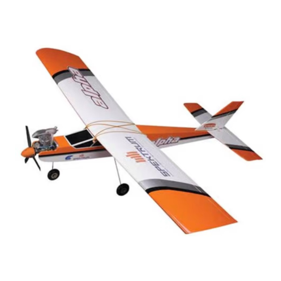
Specifications
Wing Span
.64-3/4 inches
Wing Area
.712-1/4 inch2
Approx. Weight
.4-3/4-5 1/2 lbs.
Engine Requirements
.40-.46 2-cycle
.40-.50 4-cycle
HANGAR
9
TM
INSTRUCTION MANUAL
Raising the Standard of Quality
in Almost-Ready-To-Fly Aircraft
• True UltraCote™ covering
• Positive self-righting flight characteristics
• 90% pre-built
• Extensive hardware kit included
• Break away motor mount prevents engine
damage during minor nose-overs
90
%
PRE-BUILT
ALMOST READY-TO-FLY
Advertisement
Table of Contents

Related Manuals for Hangar 9 Easy Fly 40


Summary of Contents for Hangar 9 Easy Fly 40
-
Page 1: Instruction Manual
HANGAR INSTRUCTION MANUAL Specifications Wing Span .64-3/4 inches Wing Area .712-1/4 inch2 Approx. Weight .4-3/4-5 1/2 lbs. Engine Requirements .40-.46 2-cycle .40-.50 4-cycle Raising the Standard of Quality in Almost-Ready-To-Fly Aircraft • True UltraCote™ covering • Positive self-righting flight characteristics •... - Page 2 ICKET R/C Pilot Program The Total Training Package Congratulations on your selection of the Hangar 9 Easy Fly 40! Your kit comes complete with the “T ICKET Pilot Program,” a detailed video instruction guide designed to help beginners become successful pilots.
-
Page 3: Table Of Contents
Table Of Contents Introduction Contents Of Kit Equipment Required Tools And Supplies Required Field Equipment Required Optional Field Equipment Section 1: Assembling The Wings Section 2: Joining The Wing Halves Section 3: Hinging The Rudder And Elevator Section 4: Installing The Aileron Servo Trays Section 5: Assembling The Fuselage Section 6: Installing The Nose Gear Section 7: Installing The Wing Dowels... -
Page 4: Introduction
In order for you to get the best performance and most enjoyment from your Easy Fly 40, it is important to carefully read and follow this manual. If you’re a first-time flier, we strongly suggest that you seek qualified help during your first flights. -
Page 5: Contents Of Kit
Contents Of Kit Fuselage (#HAN1401) Vertical stabilizer with rudder (#HAN1403) Right wing half with aileron (#HAN1402) Horizontal stabilizer with elevator (#HAN1404) Left wing half with aileron (#HAN1402) Pushrods Wheels (3) Aileron servo mounts (2) Fuel tank and hardware Main landing gear Rubber bands (8) Nose landing gear Control horns... -
Page 6: Equipment Required
Equipment Required R/C Radio System R/C Engine 4 Channels (minimum) .40-.45 2-Cycle with Muffler 4 Standard Servos Standard 450-650 mAh Battery Recommended JR Systems Recommended Thunder Tiger Engine JR F400 FM GP .42 with Muffler JR XP642 JR XP783 R/C Aircraft Propeller JR XP8103 10-6 Prop with a .40-.46 Size Engine Tools And Supplies Required... -
Page 7: Field Equipment Required
Field Equipment Required HAN3000 – 2-cycle Performance Plug MDC101 Glow Driver Model Airplane Fuel HAN 3005 – Extra Life Sport Plug HAN104 12V Super Starter HAN102 12V Battery HAN118 Fuel Pump HAN2510 Glow Plug Wrench... -
Page 8: Optional Field Equipment
Optional Field Equipment Extra Propellers Flight Box Power Panel Prop Wrench Miscellaneous Tools Paper Towels #64 Rubber Bands After Run Oil Extra Glow Plugs... -
Page 9: Section 1: Assembling The Wings
Section 1: Assembling The Wings Parts Needed Tools Needed Left Wing Panel with Aileron and Hinges Paper Towels CA Remover Right Wing Panel with Aileron and Hinges Rubbing Alcohol 30-Minute Epoxy Toothpicks Thin Instant CA Glue 1. Carefully remove the aileron from the right wing panel. 5. -
Page 10: Section 2: Joining The Wing Halves
Section 2: Joining The Wing Halves Parts Needed Tools Needed Aileron Servo Mounts (2) 30-Minute Epoxy Pencil Dihedral Brace Hobby Knife Rubbing Alcohol Left Wing Half from Section 1 Masking Tape Ruler Right Wing Half from Section 1 Paper Towels Wax Paper Standard Servo (1) 1. - Page 11 Section 2: Joining The Wing Halves CONTINUED 3. Locate the dihedral brace (also called the wing joiner). 5. Coat one half of the dihedral brace with epoxy up to the Using a ruler and pencil, mark the exact center of the line.
- Page 12 Section 2: Joining The Wing Halves CONTINUED 6. Apply epoxy to the exposed area (other end) of the 7. Carefully slide the two wing halves together. Firmly dihedral brace. Uniformly coat both wing roots with press the two halves together, allowing the excess 30-minute epoxy.
-
Page 13: Section 3: Hinging The Rudder And Elevator
Section 3: Hinging The Rudder And Elevator Parts Needed Tools Needed Horizontal Stabilizer with Elevator and Hinges CA Remover Vertical Stabilizer with Rudder and Hinges Paper Towels Thin Instant CA Glue 1. Push the elevator and horizontal stabilizer together until 4. -
Page 14: Section 4: Installing The Aileron Servo Trays
Section 4: Installing The Aileron Servo Trays Parts Needed Tools Needed Masking Tape Clips (e.g., clothespins, Aileron Servo Trays (2) Paper Towels binder clips) (4) Wing Center Section Tape Pencil 5-Minute Epoxy Ruler Hobby Knife 1. Mix a small amount of 5-minute epoxy as per the 4. - Page 15 Section 4: Installing The Aileron Servo Trays CONTINUED 6. Unclamp the aileron tray when dry and position it on 9. Carefully remove the covering in the aileron tray area. the center line so the two marks are visible on the This is necessary so that the tray will properly adhere to inside of the aileron tray.
- Page 16 Section 4: Installing The Aileron Servo Trays CONTINUED 11. Place the aileron tray, glue side down, on the exposed 13. Locate the wing center tape (white adhesive-backed wood area on the bottom of the wing and gently press it tape) and remove the adhesive backing. Starting at the into position.
-
Page 17: Section 5: Assembling The Fuselage
Section 5: Assembling The Fuselage Parts Needed Tools Needed Fuselage Drill with 1/16” Drill Bit Main Landing Gear (2 pcs) #1 and #2 Phillips Screwdrivers Main Landing Gear Hardware Thread Lock Wheels (2 pcs) Wheel Collars with Screws (2 pcs) 1. -
Page 18: Section 6: Installing The Nose Gear
Section 6: Installing The Nose Gear Parts Needed Tools Needed Nose Gear Wheel (1) #2 Phillips Screwdriver Spring Wheel Collar with Screws (2) Thread Lock Steering Arm 1. The nose gear mount is pre-assembled onto the front 3. Attach the nose wheel and hold it in place using a firewall of the fuselage. -
Page 19: Section 7: Installing The Wing Dowels
Section 7: Installing The Wing Dowels Parts Needed Tools Needed Fuselage CA Remover Paper Towel Wing Dowels (2) Hobby Knife Thin Instant CA Glue 1. Using a sharp hobby knife, carefully cut the covering 2. Install the two dowels and position them so that an around the four holes as shown, leaving a circle that the equal amount of dowel extends from each side of the dowel will be pressed into. -
Page 20: Section 8: Assembling The Fuel Tank
Section 8: Assembling The Fuel Tank Parts Needed Tools Needed Clunk (brass fuel pickup) Fuel Tank Hobby Knife Copper Tube, Long (vent) Plastic Cups (2) #1 Phillips Screwdriver Copper Tube, Short (pickup) Rubber Stopper Fuel Line, Small 3mm Screw and 3mm Nut 1. - Page 21 Section 8: Assembling The Fuel Tank CONTINUED 5. Locate the small diameter fuel tubing and cut it to 3” 7. Press the 3mm locknut between the three pegs on the in length. This tubing will be used for the fuel pick-up inside white plastic cap as shown.
-
Page 22: Section 9: Installing The Fuel Tank
Section 8: Assembling The Fuel Tank CONTINUED 9. Insert a 3mm screw into the center hole of the stopper Important: and tighten. Remember which tube is the fuel pick-up and which is the vent so that you can properly connect the fuel tank to the engine in Section 12. -
Page 23: Section 10: Installing The Control Horns
Section 10: Installing The Control Horns Parts Needed Tools Needed Control Horn with Backplate (2) Drill with 1/16” Drill Bit Horizontal Stabilizer with Elevator Pencil Small Phillips Screw (4) #1 Phillips Screwdriver Vertical Stabilizer with Rudder Ruler 1. Position one of the control horns on the bottom of the 3. - Page 24 Section 10: Installing The Control Horns CONTINUED 5. Position the rudder control horn as shown, with the 6. Now mark, drill, and install the horn as you did mark just below the edge of the control horn. previously for the elevator.
-
Page 25: Section 11: Installing The Horizontal & Vertical Stabilizers
Section 11: Installing The Horizontal & Vertical Stabilizers Parts Needed Tools Needed Hobby Knife 90-Degree Triangle Fuselage Ruler Pencil Horizontal Stabilizer Assembly 30-Minute Epoxy Rubbing Alcohol Vertical Stabilizer Assembly Paper Towels 1. Using a hobby knife, carefully cut out the covering at 3. - Page 26 Section 11: Installing The Horizontal & Vertical Stabilizers CONTINUED 5. Mix approximately 1 ounce of 30-minute epoxy. Apply 7. Apply 30-minute epoxy to the area on the vertical a generous amount of epoxy to the rear fuselage section stabilizer wood section from which you cut the covering where the horizontal stabilizer mounts.
-
Page 27: Section 12: Installing The Engine
Section 12: Installing The Engine Tools Needed Parts Needed Engine (not included) Drill with 1/8” Drill Bit Engine Mounts (2) Pencil Engine Screws, Nuts, Washers (8) #2 Phillips Screwdriver Fuel Tubing Fuselage 1. Locate the two engine mounts. Note that they are cut on 3. - Page 28 Section 12: Installing The Engine CONTINUED 5. Remove the engine and mounts and drill four 1/8” 7. Place the engine and the motor mounts in the desired holes through the fuselage where marked. position. It is helpful to have the prop and spinner installed at this time to check the clearance.
- Page 29 Special Instructions for Installing a 4-Cycle Engine The Easy Fly 40 is designed to also accept .40-.65 4-cycle engines. The installation is similar to the 2-cycle engine installation except that it may be...
-
Page 30: Section 13: Installing The Radio
Section 13: Installing The Radio Parts Needed Tools Needed 4-Channel Radio System with 4 Standard Servos and Drill with 1/16” Drill Bit Hardware (not included) Hobby Knife Fuselage Pencil Radio Packing Foam (not included) #1 Phillips Screwdriver Wing Installing the Aileron Servo 3. -
Page 31: Installing The Receiver And Battery
Section 13: Installing The Radio CONTINUED Installing the Rudder, Elevator, and Throttle Installing the Receiver and Battery Servos 1. Radio packing foam (available at your local hobby shop) should be used to install the receiver and battery. 1. Locate the other three servos and install the grommets With a sharp hobby knife, cut a layer of foam the size of and eyelets in all three per the instructions included the compartment in front of the servo tray and place it... - Page 32 Section 13: Installing The Radio CONTINUED Installing the Switch 1. The switch should be mounted on the left side of the fuselage, away from the exhaust gases. Place the switch plate against the side of the fuselage, as shown, and mark the position of the holes and square. 2.
-
Page 33: Section 14: Installing The Linkages
Section 14: Installing The Linkages Parts Needed Tools Needed Aileron Horn (2) 1/16” Plain Rod, Long (2) Drill with 1/16“ Drill Bit Thick CA Glue Balsa Dowel (2) 1/16” Plain Rod, Short (2) Heat Gun Z-Bender Pliers Fuselage and Wing Plastic Clevis (4) Hobby Knife or Scissors Heat Shrink Tubing... - Page 34 Section 14: Installing The Linkages CONTINUED 5. Screw both aileron horns onto the aileron torque rods Assembling the Pushrods until the threaded portion is flush with the aileron horn. 1. Locate the two balsa dowels, the two remaining threaded rods, two short plain rods, and the black heat shrink tubing.
- Page 35 Section 14: Installing The Linkages CONTINUED 3. Drill four 1/16” holes through the balsa dowel at the 5. Locate one balsa dowel and insert the 90-degree end of marks, as shown. one threaded rod into the previously drilled 1/16” hole. Cover the portion of the rod that touches the dowel with thick CA glue.
- Page 36 Section 14: Installing The Linkages CONTINUED 7. Locate the short plain rod and insert the 90-degree Installing the Pushrods angle into the opposite end of the balsa dowel. Using thick CA glue, adhere and heat shrink it into place. 1. Insert one of the pushrods, threaded rod first, into the tail of the fuselage so that the threaded rod exits the rudder pushrod exit hole.
- Page 37 Section 14: Installing The Linkages CONTINUED 3. Center the rudder and the rudder servo so that the servo 5. Use the same procedure to install the elevator pushrod, arm is perpendicular to the fuselage. Mark the plain noting that the elevator pushrod exits the rear opening rod where it crosses the holes in the servo horn.
- Page 38 Section 14: Installing The Linkages CONTINUED 7. Using the same technique as above with the rudder, make a z-bend at both ends of the plain rod with one end attached to the steering arm and the other attached to the opposite side of the rudder servo horn. With the servo horn centered, adjust the nose wheel so it’s straight.
-
Page 39: Section 15: Setting Up The Radio
2. Remove all four servo horns from the servos. Center the trims on the transmitter and move the throttle to the ELEVATOR THROW GAUGE EASY FLY 40 HINGE middle position. Turn on the transmitter and then the LINE 1/4”... -
Page 40: Section 16: Balancing The Model
Section 16: Balancing The Model Parts Needed Tools Needed Rubber Bands Pencil Ruler 1. Measure back 3-1/4” from the wing’s leading edge and put a mark on the bottom of the wing, (approximately 6” out from the center section).Repeat this procedure for the opposite wing half. -
Page 41: Pre-Flight Check
Pre-Flight Check 1. Check that all control functions move in the correct direction. If not, use the respective reversing switch to correct the direction. CARBURETOR ELEVATOR 1/16” THROTTLE ELEVATOR RUDDER AILERON AILERON RUDDER 2. Check that each clevis is securely snapped into position. -
Page 42: Pre-Flight At The Field
Pre-Flight At The Field Range Test Your Radio 1. Before each flying session range check your radio. This is accomplished by turning on your transmitter with the antenna collapsed. Turn on the radio in your airplane. With your airplane on the ground, you should be able to walk 30 paces away from your airplane and still have complete control of all functions. -
Page 43: Flight Instructions
Easy Fly 40 alone. Seek an experienced instructor. Your local hobby shop can put you in touch with an instructor in your area who can fly and trim your Easy Fly 40 and then give you your first chance on the “sticks" with very little risk of damage to the airplane. -
Page 44: Ama Safety Code
AMA Safety Code 1994 Official AMA National Model Aircraft Safety Code I will not operate models with pyrotechnics (any device that explodes, burns, or propels a projectile of any kind) including, but not limited Effective January 1, 1994 to, rockets, explosive bombs dropped from models, smoke bombs, Model flying must be in accordance with this Code in all explosive gases (such as hydrogen-filled balloons), ground order for AMA liability protection to apply... -
Page 45: Glossary
Glossary Adverse Yaw. Some airplanes, especially high-wing airplanes Expanded Scale Voltmeter (ESV). This device is used to with flat-bottom airfoils, have a tendency to yaw in the opposite check the voltage of the battery pack. direction of the bank. This is most common when flying at low speeds with high angles. - Page 46 Glossary CONTINUED NiCad. This abbreviation stands for Nickel Cadmium, the Spinner. Term describing the nose cone that covers the chemical compound used in rechargeable batteries. propeller hub. Nitro. Short for nitromethane, a fuel additive that improves an Switch Harness. This switch is commonly located on the airplane's high-speed performance.
- Page 48 ELEVATOR THROW GAUGE EASY FLY 40 HINGE LINE 1/4” Neutral 1/4” AILERON THROW GAUGE EASY FLY 40 HINGE LINE 1/4” Neutral 1/4” RUDDER THROW GAUGE EASY FLY 40 HINGE LINE 1/4” Neutral 1/4”...
- Page 49 © Copyright 1994, Horizon Hobby Distributors, Inc.
Need help?
Do you have a question about the Easy Fly 40 and is the answer not in the manual?
Questions and answers