Table of Contents
Advertisement
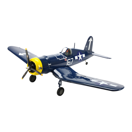
F4U Corsair .60 ARF
Specifications
Wingspan: .............. 65.25 in (1657mm)
Wing Area:............. 752 sq in (48.5 sq dm)
Length: .................... 51.5 in (1308mm)
Weight: ................... 7.5–.8.5 lb (3.4 kg–3.85 kg)
WE GET PEOPLE FLYING
ASSEMBLY MANUAL
Recommended Engines:
Radio: ...................... 5-channel w/6 servos
TM
®
.61–.75 2-stroke
.91–1.0 4-stroke
Advertisement
Table of Contents

Related Manuals for Hangar 9 F4U Corsair .60 ARF


Summary of Contents for Hangar 9 F4U Corsair .60 ARF
- Page 1 ® WE GET PEOPLE FLYING F4U Corsair .60 ARF ASSEMBLY MANUAL Specifications Wingspan: ....65.25 in (1657mm) Recommended Engines: .61–.75 2-stroke Wing Area:..... 752 sq in (48.5 sq dm) .91–1.0 4-stroke Length: ....51.5 in (1308mm) Radio: ...... 5-channel w/6 servos...
-
Page 2: Table Of Contents
Table of Contents Table of Contents ............. . 2 Covering Colors . -
Page 3: Contents Of Kit
Contents of Kit Large Parts A. Fuselage HAN2577 B. Wing Set w/Joiner and Ailerons HAN2576 C. Tail Set HAN2578 D. Canopy HAN2586 E. Painted Cowl HAN2579 F. Cockpit w/Radiator HAN2585 G. Wheel Wells HAN2589 H. Dummy Engine HAN2587 Small Parts 1. -
Page 4: Additional Required Tools And Adhesives
Other Items Needed (not included in the kit) • Propeller • 703 Low–Profile Retract Servo (JRPS703) 14x8 - Saito, 12x6 or 13x6 - Evolution • Large servo Arm w/Screw (JRPA212) • Safety spinner for engine • 9" Servo Lead Extension (JRPA097) (2) HIGSPN008 - Saito, HIGSPN014 - Evolution •... -
Page 5: Before Starting Assembly
Before Starting Assembly Before beginning the assembly of the Corsair, remove each part from its bag for inspection. Closely inspect the fuselage, wing panels, rudder, and stabilizer for damage. If you find any damaged or missing parts, contact the place of purchase. If you find any wrinkles in the covering, use a heat gun or covering iron to remove them. -
Page 6: Section 1: Joining The Wing Halves
Section 1: Joining the Wing Halves Required Parts Step 2 • Left and right wing panels • Center wing panel Remove the tape from the string located in the outer wing panel. Tape the string to the retract linkage so it •... - Page 7 Section 1: Joining the Wing Halves Step 4 Step 6 Test the fit of the wing joiner into one of the outer Use a hobby knife to remove the covering from the wing panels. The joiner should slide into the panel opening in the center panel for the retract servo.
- Page 8 Section 1: Joining the Wing Halves Hint: It is extremely important to use plenty Step 9 of epoxy when joining the wing panels. It Completely coat the short half of the wing joiner will also be helpful to use wax paper under with epoxy.
- Page 9 Section 1: Joining the Wing Halves Step 11 Step 14 Apply epoxy to the exposed portion of Use masking tape to securely hold the wing panels the wing joiner. together. Allow the epoxy to fully cure before continuing to the next section. Step 12 Step 15 Apply epoxy to root wing rib of both panels.
-
Page 10: Section 2: Attaching The Wing
Section 2: Attaching the Wing Required Parts Step 3 • Assembled wing • Fuselage Use the two 1/4 x 1 " socket head bolts and 1/4" • 1/4-20 blind nut (2) • 1/4" washer (2) washers to attach the wing to the fuselage. •... -
Page 11: Section 3: Installing The Horizontal Stabilizer
Section 3: Installing the Horizontal Stabilizer Required Parts Step 2 • Assembled wing • Fuselage Check the distance from each stab tip to each wing tip. These measurements must be equal for • Stabilizer • Elevator joiner wire the stab to be aligned. Required Tools and Adhesives •... - Page 12 Section 3: Installing the Horizontal Stabilizer Step 4 Step 6 After verifying the alignment of the stabilizer, use Slide the elevator joiner wire into the slot for a felt-tipped pen to trace the outline of the fuselage the stabilizer. Slide the stabilizer partially back on the stab.
-
Page 13: Section 4: Installing The Vertical Stabilizer
Section 4: Installing the Vertical Stabilizer Required Parts Step 2 • Fuselage assembly • Fin Locate the tail wheel wire. Slide the steering control arm onto the wire as shown. • Tail wheel wire • Steering control arm • Tail wheel wire support bracket Required Tools and Adhesives •... - Page 14 Section 4: Installing the Vertical Stabilizer Step 4 Step 6 Remove the fin and use a hobby knife with a new Cut a slot in the bottom of the aft edge of the fin for blade to remove the covering 1/16" below the lines the bracket.
- Page 15 Section 4: Installing the Vertical Stabilizer Step 8 Step 10 Mix 1/2 ounce of 30-minute epoxy. Apply the Measure 3/4" up from the fuselage and mark the epoxy to both the exposed wood on the fin and the tail wheel wire. Position the wire so the tail wheel slot in the fuselage.
-
Page 16: Section 5: Installing The Ailerons
Section 5: Installing the Ailerons Required Parts • Wing • CA hinges (6) • Aileron (left and right) Required Tools and Adhesives • Thin CA • T-Pins Step 1 Locate three CA hinges. Place a T-pin in the center of each hinge. -
Page 17: Section 6: Installing The Elevators
Section 5: Installing the Ailerons Step 5 Step 6 Firmly grasp the wing and aileron and gently pull on Work the aileron up and down several times to work the aileron to ensure the hinges are secure and in the hinges and check for proper movement. cannot be pulled apart. - Page 18 Section 5: Installing the Ailerons Note: You can combine the previous step with Step 2 the following step if you like. This will hold Locate three CA hinges. Place a T-pin in the center of the elevator in position while the epoxy cures. the hinges.
-
Page 19: Section 7: Installing The Rudder
Section 5: Installing the Ailerons Step 7 Step 8 Hold the remaining elevator in position against the Drill the location marked in the previous step using stabilizer. Mark the location of the elevator joiner a 9/64" drill bit. wire onto the elevator. Step 9 Repeat Steps 2 through 6 to install the remaining elevator half. - Page 20 Section 7: Installing the Rudder Step 2 Step 5 Drill the location marked in the previous step using Locate two CA hinges and place a T-pin in the center a 1/8" drill bit. of each hinge. Place the hinges into the rudder. Step 6 Test fit the rudder to the fin and tail wheel wire.
- Page 21 Section 7: Installing the Rudder Step 10 Step 12 Once the CA and epoxy have fully cured, gently pull Remove the covering from the fuselage and the on the fin and rudder to make sure the hinges are bottom of the trim piece. well glued.
-
Page 22: Section 8: Retract Linkage Installation
Section 8: Retract Linkage Installation Required Parts Step 3 • Quick connector (2) • 3mm set screw (2) Locate the retract servo tray. Use 6-minute epoxy to glue the servo tray into position. • 3 " main wheel (2) • 5/32" wheel collar (2) •... - Page 23 Section 8: Retract Linkage Installation Step 6 Step 9 Use a 5/64" drill bit to drill the appropriate holes With the retract servo in the retracted position, in the arm. push the retract linkage to manually retract the landing gear. Install 3mm set screws into the quick connectors and tighten them to secure the retract linkage.
- Page 24 Section 8: Retract Linkage Installation Hint: Adjustments and fine tuning can also Step 12 be made to the retract linkages from inside Install a wheel and two wheel collars on the main the wheel wells. landing gear. The order of items is 5/32" wheel collar, wheel, and then another wheel collar.
-
Page 25: Section 9: Engine Installation
Section 9: Engine Installation Required Parts Hint: You can also install the blind nuts backwards to prevent them from pulling into • Fuselage • Engine mount (2) the wood on the backside of the firewall. Just • 8-32 nylon lock nut (4) •... -
Page 26: Section 10: Throttle Pushrod Installation
Section 9: Engine Installation Step 5 Center the engine mount in relationship to the oval holes in the firewall. Tighten the bolts holding the mount to the firewall. (Remember to make sure the barbs on the blind nuts go into the backside of the firewall.) Section 10: Throttle Pushrod Installation Required Parts... - Page 27 Section 10: Throttle Pushrod Installation Step 2 Step 4 Drill a 5/32” hole in former 2 that corresponds to the Position the throttle servo tray so the opening for the location of the hole drilled in the firewall. servo is on the same side of the fuselage as the throttle pushrod tube.
-
Page 28: Section 11: Fuel Tank Assembly
Section 10: Throttle Pushrod Installation Step 6 Attach the "Z" bend on the throttle pushrod wire onto the carburetor arm. Slide the pushrod wire into the tube and secure the engine to the firewall. Section 11: Fuel Tank Assembly Required Parts Step 1 •... - Page 29 Section 11: Fuel Tank Assembly Step 2 Step 4 Locate the rubber stopper. Insert the shorter metal Bend the longer fuel tube carefully to a fuel tube into one of the holes in the stopper so that 45-degree angle using your fingers. This will an equal amount of tube extends from each side of be the fuel tank vent tube.
- Page 30 Section 11: Fuel Tank Assembly Step 6 Step 8 Locate the short piece of silicone fuel tubing and the Tighten the M3 x 20 screw carefully—do not over fuel tank clunk. Install the clunk onto one end of the tighten. This allows the rubber stopper to form a seal silicone tubing.
-
Page 31: Section 12: Fuel Tank Installation
Section 12: Fuel Tank Installation Required Parts Step 3 • Fuselage assembly • Fuel tank assembly Install the fuel tank into the fuselage. Make any necessary supports to keep the tank from • Fuel tubing moving during flight. Required Tools and Adhesives •... -
Page 32: Section 13: Radio Installation
Section 12: Fuel Tank Installation Step 5 Make the proper connections to the engine, using the engine manufacturer’s instructions. If you are using a four-stoke, make sure to route the crankcase vent to the outside of the cowling. Section 13: Radio Installation Required Parts Step 2 •... - Page 33 Section 13: Radio Installation Step 3 Step 5 Remove the servo and drill the holes for the servo Remove the covering from the opening on the bottom mounting screws using a 1/16" drill bit. of the fuselage for the rudder servo. Hint: Place a drop of thin CA onto each Step 6 screw hole to harden the wood around the...
- Page 34 Section 13: Radio Installation Step 7 Step 9 Temporarily install the rudder servo. Mark the Mount the radio switch to the side of the fuselage. locations for the servo screws using a felt-tipped pen. Remove the servo and drill the holes for the servo mounting screws using a 1/16"...
- Page 35 Section 13: Radio Installation Step 12 Step 15 Temporarily mount the receiver and battery into the Install the recommended servo hardware (grommets fuselage. It may be necessary to relocate the battery and eyelets) supplied with the servo. Temporarily forward or aft to balance the model as described in install a long half servo arm (JRPA212) onto the the section "Control Throws and Center of Gravity."...
- Page 36 Section 13: Radio Installation Step 17 Step 19 Place the aileron servo between the mounting blocks Connect a 12" Servo Lead extension (JRPA098) to and use a felt-tipped pen to mark the location of the the servo lead. Secure the connectors by tying them four servo mounting screws.
- Page 37 Section 13: Radio Installation Step 22 Remove the servo hatch cover and re-drill the holes using a 5/64" drill bit. Use 2–3 drops of thin CA to harden the underlying wood. This will prevent the screws from crushing the wood when they are tightened.
-
Page 38: Section 14: Linkage Installation
Section 14: Linkage Installation Required Parts Step 3 • Fuselage assembly • Wing assembly Position the control horn on the elevator so the horn aligns with the hinge line of the elevator. Mark • 6" pushrod wire (3) • 7" pushrod wire the position for the mounting holes using a •... - Page 39 Section 14: Linkage Installation Step 5 Step 7 Place 2–3 drops of thin CA into the hole to harden Center the elevator servo electronically using the the wood. Repeat this for each of the three holes. radio system. Install a servo arm onto the elevator servo.
- Page 40 Section 14: Linkage Installation Step 9 Step 12 Cut the wire 3/8" above the bend. Center the rudder servo electronically using the radio system. Install a servo arm onto the rudder servo. Attach the pushrod with clevis to the steering control horn.
- Page 41 Section 14: Linkage Installation Step 14 Step 17 Slide the wire through the outer hole in the rudder Position the control horn on the aileron so the horn servo arm. Secure the wire using a nylon wire keeper. aligns with the aileron servo horn and the aileron It may be necessary to drill out the hole in the servo hinge line.
- Page 42 Section 14: Linkage Installation Step 20 Step 24 Slide a clevis retainer onto a nylon clevis. Thread a Repeat Steps 16 through 23 for the other clevis onto a 6" wire a minimum of 10 turns. aileron servo. Step 21 Step 25 Center the aileron servo electronically using the radio Use a 5/64"...
- Page 43 Section 14: Linkage Installation Step 27 Step 30 Center the throttle stick and trim with both the Use scrap wood to make a brace for the throttle receiver and transmitter on. Install the throttle servo pushrod tube near the servo as shown. arm in the neutral position.
-
Page 44: Section 15: Cowling Installation
Section 15: Cowling Installation Required Parts Step 2 • Fuselage assembly • Cowling Use 6-minute epoxy to glue the dummy radial inside the cowl. • #2 x 1/2" sheet metal screw (4) • 5/8" x 3/4" x 3/4" cowl mounting block (4) •... - Page 45 Section 15: Cowling Installation Step 4 Step 6 Sand four areas onto the firewall that are 45 degrees Use a piece of cardstock to indicate the location from the centerlines. The areas must be large enough of the engine head, needle valve and cowl to fit the cowl mounting blocks.
- Page 46 Section 15: Cowling Installation Step 8 Step 10 Remove the cowl and remove the necessary material Use the cardstock from Step 1 to locate the positions to fit the cowl over the engine. Install the engine back for the cowling screws. The goal is to drill into the onto the firewall and test fit the cowl over the engine.
-
Page 47: Section 16: Canopy And Decal Installation
Section 16: Canopy and Decal Installation Required Parts Step 2 • Fuselage assembly • Canopy Position the canopy onto the fuselage. Trace around the canopy and onto the fuselage using a • #2 x 1/2" sheet metal screw (2) felt-tipped pen. Required Tools and Adhesives •... -
Page 48: Adjusting The Engine
Section 16: Canopy and Decal Installation Step 4 Step 6 Apply a bead of RCZ56 Canopy Glue (ZINJ5007) Use Lexan ® scissors to trim the radiators. Use around the inside edge of the canopy. Position the Zap-A-Dap-A-Goo to glue the radiators into position canopy onto the hatch. -
Page 49: Range Testing The Radio
Control Throws and Center of Gravity Recommended CG Location Moving it toward the control surface will increase the amount of throw. Moving the pushrod wire at the An important part of preparing the aircraft for flight servo arm will have the opposite effect: Moving it is properly balancing the model. -
Page 50: 2003 Official Ama National Model Aircraft Safety Code
2003 Official AMA National Model Aircraft Safety Code Effective January 1, 2003 Model Flying MUST be in accordance with this Code in order for AMA Liability Protection to apply. GENERAL 7) I will not operate models with pyrotechnics (any device that explodes, burns, or propels a projectile of any kind) 1) I will not fly my model aircraft in sanctioned events, air including, but not limited to, rockets, explosive bombs... - Page 51 2003 Official AMA National Model Aircraft Safety Code Continued 4) I will operate my model using only radio control Organized RC Racing Event frequencies currently allowed by the Federal 10) An RC racing event, whether or not an AMA Rule Communications Commission.
- Page 52 ® WE GET PEOPLE FLYING © 2003, Horizon Hobby, Inc. 4105 Fieldstone Road Champaign, Illinois 61822 (877) 504-0233 www.horizonhobby.com 6111...
Need help?
Do you have a question about the F4U Corsair .60 ARF and is the answer not in the manual?
Questions and answers