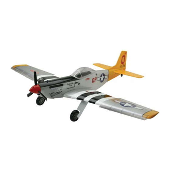
Hangar 9 P-51 Mustang ARF Instruction Manual
Sport scale model
Hide thumbs
Also See for Hangar 9 P-51 Mustang ARF:
- Assembly manual (72 pages) ,
- Installation manual (7 pages) ,
- Assembly manual (56 pages)
Table of Contents
Advertisement
INSTRUCTION MANUAL
• 90% prebuilt
• Great sport scale appearance
• Factory installed retracts
• Precovered in genuine UltraCote
• Prepainted fiberglass cowl
Specifications
Wingspan: ............................................................................................................ 65.5 in (1663.7 mm)
Fuselage Length: .................................................................................................. 55.75 in (1416 mm)
Wing Area: ...................................................................................................... 745 sq in (48.1 sq dm)
Weight (Approx.): ............................................................................................. 7– 8.5 lb (3.2–3.9 kg)
Recommended Engines: ......................................................................................... 2-cycle: .60 –.78
TM
TM
WE GET PEOPLE FLYING
®
4-cycle: .72–1.00
3953 HAN2375
Advertisement
Table of Contents

Related Manuals for Hangar 9 Hangar 9 P-51 Mustang ARF


Summary of Contents for Hangar 9 Hangar 9 P-51 Mustang ARF
-
Page 1: Instruction Manual
WE GET PEOPLE FLYING INSTRUCTION MANUAL • 90% prebuilt • Great sport scale appearance • Factory installed retracts • Precovered in genuine UltraCote ® • Prepainted fiberglass cowl Specifications Wingspan: ......................65.5 in (1663.7 mm) Fuselage Length: ....................55.75 in (1416 mm) Wing Area: ...................... -
Page 2: Table Of Contents
Table of Contents Introduction ............................3 Warning .............................. 3 Additional Required Equipment ......................4 Contents of Kit............................ 5 Section 1: Hinging the Ailerons......................6 Section 2: Joining the Wing Halves....................8 Section 3: Installing the Aileron Servos ....................10 Section 4: Installing the Aileron Control Horns and Linkages ............13 Section 5: Installing the Retract Servo ....................15 Section 6: Installing the Main Landing Gear Wheels and Fairings............18 Section 7: Mounting the Wing to the Fuselage................. -
Page 3: Introduction
If you encounter difficulty in any construction sequence, please feel free to contact one of our technicians—we stand ready to provide any assistance we can concerning the construction of your Hangar 9 P-51 .60-Size ARF. You can contact us at: Horizon Hobby, Inc. 4105 Fieldstone Road Champaign, Illinois 61822 (217) 355-9511 www.horizonhobby.com... -
Page 4: Additional Required Equipment
Additional Required Equipment (not included) Radio Equipment 5-channel radio system (minimum) 5 standard servos (JRPS537 recommended or equivalent) 1 low-profile retract servo (JRPS703) ™ Recommended JR Systems JR XF652 JR XP783 JR 8103 JR 10X JR XP8103 PCM 10X Engine Requirements .60–.78 2-cycle engines .72–1.00 4-cycle engines MDS .68... -
Page 5: Contents Of Kit
Contents of Kit Main Parts Other Parts A. Fuselage (HAN2377) 1. Main and tail wheels B. Wing Set w/Joiner (HAN2376) (retract not included) 2. Fuel tank C. Tail Set (HAN2378) 3. Scale details D. Fiberglass Cowl (HAN2380) 4. Landing gear fairings E. -
Page 6: Section 1: Hinging The Ailerons
Section 1 Hinging the Ailerons CONTINUED Part Needed Step 3 photo Right and left wing panels Tools and Adhesives Needed Instant thin CA glue CA remover/debonder Paper towels T-pins (one for each hinge) Caution: The control surfaces, including the ailerons, elevators, and rudder come with the hinges installed, but the hinges are not glued in place. -
Page 7: Hinging The Ailerons
Section 1 Hinging the Ailerons CONTINUED Step 5. Turn the wing panel over, deflect the aileron in the Step 8. Allowing time for both ailerons to completely dry, opposite direction, and apply thin CA to the other side of the firmly grasp the wing and aileron and applying medium pressure hinges as in the previous step. -
Page 8: Section 2: Joining The Wing Halves
Section 2 Joining the Wing Halves CONTINUED Parts Needed Step 2 photo Right wing panel assembly Left wing panel assembly Wing joiner Tools and Adhesives Needed Ruler Masking tape 30-minute epoxy Rubbing alcohol Paper towels Step 1. Locate the wing joiner. Using a ruler and felt-tipped Step 3. - Page 9 Section 2 Joining the Wing Halves CONTINUED Step 4. Mix approximately 1 ounce of 30-minute epoxy. Using Step 7 photo an epoxy brush, apply a generous amount of epoxy to the wing joiner cavity of one wing panel. Step 8. Carefully slide both wing panels together. Firmly press both halves together, allowing the epoxy to run out.
-
Page 10: Section 3: Installing The Aileron Servos
Section 3 Installing the Aileron Servos CONTINUED Parts Needed Step 2 photos Wing assembly Aileron servos w/mounting hardware (2) Servo hatch screws (#2 x 3/8") (8) 18" servo wire extension (JRPA099) (2) Large Servo Arm (JRPA212) (1 pkg.) Tools and Adhesives Needed Phillips screwdriver Thin CA Thick CA... -
Page 11: Installing The Aileron Servos
Section 3 Installing the Aileron Servos CONTINUED Step 4. Place the aileron servo between the mounting blocks Step 6 photo and using a felt-tipped pen mark the location of the four servo mounting screws. Note that the servo must not touch the hatch in order to isolate engine vibration. - Page 12 Section 3 Installing the Aileron Servos CONTINUED Step 8. Place the servo hatch assembly back into the opening Step 9. Locate four #2 x 3/8" wood screws and using a Phillips and check the fit. Once satisfied with the fit, measure in from screwdriver secure the hatch to the wing.
-
Page 13: Section 4: Installing The Aileron Control Horns And Linkages
Section 4 Installing the Aileron Control Horns & Linkages CONTINUED Parts Needed Step 3. Place the aileron control horn on the mark made in the previous step, aligning the center of the control horn on the Wing assembly mark. Also align the clevis holes in the horn with the aileron Control horn (2) hinge line as show below and mark the location of the three Horn back plate (2) - Page 14 Section 4 Installing the Aileron Control Horns & Linkages CONTINUED Step 5. Using a small Phillips screwdriver, attach the control Step 7. Remove the clevis and wire from the control horn horn using the provided hardware. and make a 90-degree bend at the mark made in the previous step.
-
Page 15: Section 5: Installing The Retract Servo
Section 5 Installing the Retract Servo CONTINUED Parts Needed Step 2. Install the servo mounting hardware included with your retract servo, (rubber grommets and eyelets). Locate the retract Wing assembly servo mounting plate included with your kit and trial fit the servo Retract servo-mounting plate into the mounting plate. - Page 16 Section 5 Installing the Retract Servo CONTINUED Step 4. Trail fit the retract servo and mounting plate to the Step 6 photo retract servo rails temporarily installed in the wing assembly. Position the servo output shaft as close to the center of the wing as shown.
- Page 17 Section 5 Installing the Retract Servo CONTINUED Step 9. Connect the retract servo to your radio system and Step 10 photo electronically move the servo to the extend position. Slide the retract control wires through the quick connects as shown and mount the servo wheel to the retract servo.
-
Page 18: Section 6: Installing The Main Landing Gear Wheels And Fairings
Section 6 Installing the Main Landing Gear Wheels and Fairings CONTINUED Parts Needed Step 3. Repeat Steps 1 and 2 for the other main landing gear wheel. Wing assembly Main landing gear wheels (2) Large wheel collars and set screws (4) Step 4. - Page 19 Section 6 Installing the Main Landing Gear Wheels and Fairings CONTINUED Step 6. With the landing gear retracted, fit the fairing to the Step 8. Position the mounting straps on their locations and use bottom of the wing as shown, lining up the trim colors on the a 3/32"...
-
Page 20: Section 7: Mounting The Wing To The Fuselage
Section 7 Mounting the Wing to the Fuselage CONTINUED Parts Needed Step 2. Locate the predrilled holes in the wing trailing edge and use a sharp hobby knife to remove the covering as shown. Fuselage Wing assembly Radiator scoop Wing bolt plate 8-32 wing mounting bolts (2) 8-32 blind nuts (2) Medium fuel tubing (1/2") - Page 21 Section 7 Mounting the Wing to the Fuselage CONTINUED Step 4. Mix 1/2 ounce of 6-minute epoxy and coat both the Step 6. Mount the wing to the fuselage using the two provided wing and plywood plate. The groove cut into the plywood plate mounting bolts and washers.
- Page 22 Section 7 Mounting the Wing to the Fuselage CONTINUED Step 9 photo Step 9 photos Step 8. With the radiator scoop properly positioned, use a pencil to trace the outline onto the wing. Use only enough pressure to make a slight indentation in the covering. Use a sharp hobby knife to cut away the covering 1/16"...
-
Page 23: Section 8: Installing The Tail Group (Horizontal And Vertical Fin)
Section 8 Installing the Tail Group (Horizontal and Vertical Fin) CONTINUED Parts Needed Step 3. Mark the center of the stabilizer saddle at the trailing edge of the saddle. You can hold the ruler at the back portion of Fuselage assembly the stab opening and use a pen or pencil to mark the center Wing assembly location through the opening of the vertical fin as shown. - Page 24 Section 8 Installing the Tail Group (Horizontal and Vertical Fin) CONTINUED Step 5. Mount the wing to the fuselage and measure the Step 8. Re-install the stabilizer into the fuselage. Use the lines distance from the wing tip to the tip of the horizontal stabilizers drawn in Step 6 to reposition the stab correctly.
- Page 25 Section 8 Installing the Tail Group (Horizontal and Vertical Fin) CONTINUED Step 10. Remove the fin and use a sharp hobby knife to remove Step 12. Remove the horizontal stabilizer and vertical fin the covering where the fin inserts into the fuselage, cutting 1/16" from the fuselage.
- Page 26 Section 8 Installing the Tail Group (Horizontal and Vertical Fin) CONTINUED Step 14. Use the remaining epoxy coat the bottom of the Step 15 photo vertical fin and the slot in the fuselage for the fin. Try to keep the epoxy away from the joiner wire.
-
Page 27: Section 9: Hinging The Elevators
Section 9 Hinging the Elevators CONTINUED Parts Needed Hint: Use a piece of masking tape on the drill bit as a depth gauge. Fuselage assembly Left and right elevator halves Hinges (6) Tools and Adhesives Needed Thin CA CA remover/debonder 6-minute epoxy Drill Drill Bit: 3/32"... -
Page 28: Hinging The Elevators
Section 9 Hinging the Elevators CONTINUED Step 4. Place a T-pin in the center of each hinge and slide the Step 7. Once the epoxy has cured, deflect the elevators hinges into the horizontal stabilizer until the T-pin is snug down and use a high-quality thin CA to completely saturate against the trailing edge as shown. -
Page 29: Section 10: Installing The Rudder And Tail Wheel Assembly
Section 10 Installing the Rudder and Tail Wheel Assembly CONTINUED Parts Needed Step 3. Using a 3/32" drill bit, drill the rudder following the marks you made in the previous step. Make sure to drill Fuselage assembly straight into the rudder. Rudder Hinges Hint: Use a piece of masking tape on the drill... - Page 30 Section 10 Installing the Rudder and Tail Wheel Assembly CONTINUED Step 5. Align the tail wheel assembly bracket with the center of Step 7. Mix at least 1/4 ounce of 6-minute epoxy and use a the fuselage and drill the screw mounting holes using a 1/16" tooth pick to coat the inside of the hole you drilled in the rudder.
- Page 31 Section 10 Installing the Rudder and Tail Wheel Assembly CONTINUED Step 9. Once the epoxy has cured, deflect the rudder fully in Step 10. Once the CA has completely dried, check the rudder one direction and saturate each hinge with thin CA. Deflect the for security by trying to pull the rudder from the fuselage.
-
Page 32: Section 11: Installing The Elevator And Rudder Control Horns
Section 11 Installing the Elevator and Rudder Control Horns CONTINUED Parts Needed Step 3. Remove the control horn and drill 1/16" holes through the elevator as marked. Make sure to drill these holes parallel to Control horn w/backplate (2) each other to allow the back plate of the horn to fit properly. Control horn screws (6) Fuselage Wing... - Page 33 Section 11 Installing the Elevator and Rudder Control Horns CONTINUED Step 6. Center the control horn over the mark you’ve just made. Step 7. Drill these holes with a 1/16" drill bit and install the Make sure the horn is positioned over the hinge line, just like rudder control horn, using the screws and backplate provided.
-
Page 34: Section 12: Assembling The Fuel Tank
Section 12 Assembling the Fuel Tank CONTINUED Parts Needed Step 3. Slide the smaller of the two caps over the tube on the smaller end of the rubber stopper. The small end will be inserted Metal tubes (1 short, 1 long) into the fuel tank. - Page 35 Section 12 Assembling the Fuel Tank CONTINUED Step 6. Locate the short piece of silicone fuel tubing and the Step 8. Tighten the 3mm screw carefully—do not over tighten. fuel tank clunk. Install the clunk onto one end of the silicone This allows the rubber stopper to form a seal by being slightly tubing and the other end onto the fuel tank pickup tube (straight compressed, thus sealing the fuel tank opening.
-
Page 36: Section 13: Mounting The Engine
Section 13 Mounting the Engine CONTINUED Parts Needed Step 3 photos Fuselage assembly Engine mount Engine mounting hardware: 8-32 x 1 " bolt (4) 8-32 x 1" bolt (4) 8-32 blind nut (4) 8-32 lock nut (4) #8 washer (8) Assembled fuel tank RC foam (not included) Tools and Adhesives Needed... - Page 37 Section 13 Mounting the Engine CONTINUED Step 4 photo Step 6 photo Step 5. Determine the proper location for the throttle pushrod. Step 7. Once the epoxy has cured, install the fuel tank into the Mark the location with a felt-tipped pen or pencil and drill the front of the fuselage.
-
Page 38: Section 14: Installing The Radio System
Section 14 Installing the Radio System CONTINUED Parts Needed Step 2 photo Fuselage assembly Servo (3) (not included) Servo lead extension (2) (24") (not included) Receiver (not included) Battery pack (not included) RC foam (not included) Antenna tube (optional) Tools and Adhesives Needed Hobby knife Drill Drill Bit: 1/16"... -
Page 39: Installing The Radio System
Section 14 Installing the Radio System CONTINUED Step 4. Install the elevator and rudder servos by feeding the Step 6. Temporarily install the throttle servo as shown with the servo lead and extensions through the fuselage. Secure the output shaft to the side of the fuselage where the pushrod is servos using the screws supplied with your radio system. -
Page 40: Section 15: Installing The Rudder, Elevator, And Throttle Linkage
Section 15 Installing the Rudder, Elevator, and Throttle Linkage CONTINUED Parts Needed Step 3. Remove the control wire and use a pair of pliers to make a 90-degree bend at the mark made in the previous step. Fuselage assembly Trim down the wire behind the 90-degree bend leaving 5/16" 6"... - Page 41 Section 15 Installing the Rudder, Elevator, and Throttle Linkage CONTINUED Step 6. Locate the throttle control wire with the Z-bend at one Step 9. With the throttle stick centered move the throttle arm on end. Slide the wire into the pushrod tube (previous installed) your engine to the center of its throw (1/2 throttle) and tighten from the firewall into the fuselage as shown.
-
Page 42: Section 16: Attaching The Cowl
Section 16 Attaching the Cowl CONTINUED Parts Needed Step 2 photo Fuselage assembly Cowl Mounting screws (4) 3.5" P-51 spinner (CBA5073) Tools and Supplies Needed Moto-tool with cut-off wheel and sanding drum Hobby knife Felt-tipped pen or pencil Masking tape Step 3. - Page 43 Section 16 Attaching the Cowl CONTINUED Step 4. Slide the cowl back into place and align the cowl Step 6. Using a 1/16" drill bit, carefully drill the four cowl as shown and tape in place using the spinner back plate (not mounting screw locations.
-
Page 44: Section 17: Application Of Decals And Scale Detailing
Section 17 Application of Decals and Scale Detailing CONTINUED Parts Needed Fuselage Plastic cockpit detail Plastic exhaust detail Decal sheet Tools and Adhesives Needed Hobby knife Canopy scissors Water spray bottle Dish soap (2–3 drops) Shoe Goo The P-51 is a sport scale reproduction of the original aircraft. We have provided side and top view photos below to help you locate the placement of the decals and cockpit detail. - Page 45 Section 17 Application of Decals and Scale Detailing CONTINUED Step 1. Using a pair of canopy scissors, cut out and trim the Step 4. Locate the decal sheet and cut out the decals for the cockpit and exhaust detail. P-51 using a sharp hobby knife and scissors. Step 2.
-
Page 46: Section 18: Attaching The Canopy
Section 18 Attaching the Canopy CONTINUED Parts Needed Step 2. Glue the canopy to the fuselage using RC560 canopy glue. Tape the canopy in place using masking tape and allow the Fuselage assembly glue to dry over night. Canopy Note: The P-51 canopy comes prepainted from Hangar 9™. Tools and Adhesives Needed Canopy scissors Canopy glue (RC560) -
Page 47: Preflight At The Field
Preflight at the Field Range Test Your Radio Adjusting Your Engine Step 1. Before each flying session, range check your radio. Step 1. Completely read the instructions included with your This is accomplished by turning on your transmitter with the engine and follow the recommended break-in procedure. -
Page 48: Radio Control
1. I will have completed a successful radio equipment ground range check before the first flight of a new or repaired model. ©2002 Horizon Hobby, Inc. 4105 Fieldstone Road, Champaign, IL 61822 www.horizonhobby.com 3953 HAN2375.46...
Need help?
Do you have a question about the Hangar 9 P-51 Mustang ARF and is the answer not in the manual?
Questions and answers