Table of Contents
Advertisement
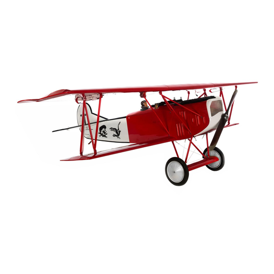
Specifications
Wingspan .....................................64.6 in (1641mm)
Length ..........................................49.8 in (1265mm)
Wing Area (Total) ..................1114 sq in (72 sq dm)
Wing Area (Top Wing) .............689 sq in (44 sq dm)
Wing Area (Bottom Wing) .......425 sq in (27 sq dm)
Wing Loading .......................................17.5 oz/sq ft
Fokker D.VII
Assembly mAnuAl
Flying Weight ...................... 8.5–9.5 lb (3.9–4.3 kg)
Engine Size ..................... .61 2-stroke, .82 4-stroke
Motor Size .................................................Power 60
Radio.........................................................4-channel
Servos .........................5 servos (4 electric) required
Advertisement
Table of Contents

Related Manuals for Hangar 9 fokker D.VII


Summary of Contents for Hangar 9 fokker D.VII
- Page 1 Fokker D.VII Assembly mAnuAl Specifications Wingspan ........64.6 in (1641mm) Flying Weight ...... 8.5–9.5 lb (3.9–4.3 kg) Length ..........49.8 in (1265mm) Engine Size ..... .61 2-stroke, .82 4-stroke Wing Area (Total) ....1114 sq in (72 sq dm) Motor Size ..........Power 60 Wing Area (Top Wing) .....689 sq in (44 sq dm)
-
Page 2: Table Of Contents
Table of Contents Using the Manual ..............3 Required Tools and Adhesives . -
Page 3: Using The Manual
Using the Manual This manual is divided into sections to help make assembly easier to understand, and to provide breaks between each major section. In addition, check boxes have been placed next to each step to keep track of each step completed. Steps ... -
Page 4: Recommended Jr, Jr Sport And Spektrum Systems
Recommended JR, JR SPORT and Spektrum Systems • JR 12X • JR 10X • JR XP9303 • JR X9303 2.4 • JR XP7202 Spektrum DX7 JR 12X JR XP9303 • Spektrum DX-7 Recommended Setup–2-Stroke Glow • Evolution ® .61NT with Muffler (EVOE0610) •... -
Page 5: Before Starting Assembly
Before Starting Assembly Before beginning the assembly of the Fokker D.VII, remove each part from its bag for inspection. Closely inspect the fuselage, wing panels, rudder, and stabilizer for damage. If you find any damaged or missing parts, contact the place of purchase. -
Page 6: Warranty Information
Warranty Information Warranty Period Exclusive Warranty- Horizon Hobby, Inc., (Horizon) warranties that the Products purchased (the "Product") will be free from defects in materials and workmanship at the date of purchase by the Purchaser. Limited Warranty (a) This warranty is limited to the original Purchaser ("Purchaser") and is not transferable. REPAIR OR REPLACEMENT AS PROVIDED UNDER THIS WARRANTY IS THE EXCLUSIVE REMEDY OF THE PURCHASER. -
Page 7: Inspection Or Repairs
Questions, Assistance, and Repairs Your local hobby store and/or place of purchase cannot provide warranty support or repair. Once assembly, setup or use of the Product has been started, you must contact Horizon directly. This will enable Horizon to better answer your questions and service you in the event that you may need any assistance. -
Page 8: Contents Of Kit
Contents of Kit A. HAN4676 Fuselage w/Hatch N. HAN4689 Cowl screws (12 pcs) B. HAN4677 Top Wing Set w/Ailerons O. HAN4690 Anodized Aluminum Wing Tube C. HAN4678 Bottom Wing Set P. HAN4692 Pushrod Set D. HAN4679 ARF Tail Set Q. HAN4693 EP Standoffs (48mm) (4Pcs) R. -
Page 9: Section 1: Radio Installation
Section 1: Radio Installation Required Parts Step 2 • Fuselage • Servo w/hardware (2) Secure the elevator servo in the fuselage using the • Receiver • Switch harness hardware provided with the servo. • Receiver battery • Hook and loop strap (2 required)) •... - Page 10 When instaling a 2.4GHz remote receiver: Step 4 Use double-sided foam tape or self-adhesive hook and Remove the covering for the switch opening using a loop material to mount the remote receiver as shown. hobby knife and #11 blade. Mount the switch to the side Keep the remote antenna(s) at least 2 inches away from of the fuselage.
-
Page 11: Section 2: Aileron Servo Installation
Section 2: Aileron Servo Installation Required Parts o Step 2 • Pushrod snap keeper (2) • Servo w/hardware (2) Use a felt-tipped pen to mark the locations for the servo • Top wing panel (right and left) mounting blocks on the hatch. •... - Page 12 o o Step 4 Step 6 Position the servo between the blocks. Use a felt-tipped Place 2–3 drops of thin CA into each hole to harden pen to transfer the locations for the servo mounting the surrounding wood. This provides a harder surface screws onto the servo mounting blocks.
- Page 13 o o Step 8 Step 10 Enlarge the hole 1/2-inch (13mm) from the center of the Tie the string located inside the wing to the aileron servo horn using a 5/64-inch (2mm) drill bit. Use side servo extension. cutters to remove any unused arms from the horn. o Step 11 o...
- Page 14 o o Step 12 Step 14 Use the string to pull the servo extension through the Attach the clevis from the 6-inch (152mm) pushrod to the wing, exiting the opening uncovered in the previous step. inside hole of the aileron control horn. A piece of safety tubing has been installed on the clevis.
- Page 15 o o Step 16 Step 17 Use pliers to make a 90-degree bend in the pushrod at the Slide the pushrod through the outer hole of the servo mark made in the previous step. arm. Use a pushrod snap keeper to secure the connection between the pushrod and servo arm.
-
Page 16: Section 3: Joining The Wing Panels
Section 3: Joining the Wing Panels Required Parts Step 2 • 15/16 x 1/4 x 6 -inch Slide the front wing spar in to the pocket in the wing. Use (24mm x 6mm x 157mm) front spar a pencil to draw a line on the spar flush against the wing. •... - Page 17 Step 4 Step 6 Repeat Steps 1 through 3 for the rear wing spar. Slide the Mix a batch of 30-minute epoxy. Use an epoxy brush to two wing panels together. apply the epoxy to ALL SIDES of the joiner. ...
- Page 18 Step 8 Step 10 Use an epoxy brush to apply epoxy to the mating surfaces Once the epoxy has fully cured, apply the 1 x 12-inch of the wing ribs of both wing panels. (25mm x 305mm) white covering to the joint made by the two wing panels.
-
Page 19: Section 4: Wing Installation
Section 4: Wing Installation Required Parts Important: Make sure to use threadlock on the screws to prevent • N-strut (right and left) • #4 washer (2) them from vibrating loose. • Heat shrink (2) • Forward wing cabane (right and left) ... - Page 20 Step 3 Step 5 Route the 12-inch servo leads from the receiver through Use a hobby knife to remove the covering from the wing, the holes in the fuselage and along the front cabanes as exposing the 4-40 blind nuts that have been installed shown.
- Page 21 o Step 7 Step 9 Slide the wing tube for the bottom wing into position in Secure the bottom wing to the fuselage using a 4-40 the fuselage. x 1/2-inch socket head screw and #4 washer. Use a 3/32-inch ball driver to tighten the screw. o Step 8 o...
-
Page 22: Section 5: Tail Installation
Section 5: Tail installation Required Parts Step 3 • Stabilizer/elevator • Rudder/fin Use a hobby knife with a new #11 blade to trim the covering slightly inside the lines drawn in the Required Tools and Adhesives previous step. • 30-minute epoxy •... - Page 23 Hint: Use a paper towel and rubbing Step 7 alcohol to remove the lines made by the Use a hobby knife with a new #11 blade to trim felt-tipped pen before the fin installation. the covering slightly inside the lines drawn in the previous step.
- Page 24 Hint: Use a paper towel and rubbing Step 9 alcohol to remove the lines made by the Apply epoxy to the stabilizer saddle of the fuselage felt-tipped pen before the fin installation. as well. Position the stabilizer and double-check the alignment to the wings.
-
Page 25: Section 6: Rudder And Elevator Linkage Installation
Section 6: Rudder and Elevator Linkage Installation Required Parts o Step 3 • 27 -inch (690mm) pushrod, rudder Center the rudder transmitter trim and rudder servo. Use • 26 -inch (680mm) pushrod, elevator a felt-tipped pen to mark the pushrod where it crosses the outer hole of the rudder servo horn. - Page 26 o Step 5 Step 6 Secure the pushrod to the rudder servo horn using a Repeat Steps 2 through 5 to install the elevator pushrod. pushrod snap keeper. Remove any excess wire extending Connect the clevis to the center hole of the elevator beyond the keeper with side cutters.
-
Page 27: Section 7: Landing Gear Installation
Section 7: Landing Gear Installation Required Parts Step 2 • Tail skid • Wheel (2) Rotate the skid down and secure it using a landing gear • Landing gear legs (2) • O-ring (4) strap and two #4 x 1/2-inch self-tapping screws. Tighten the two screws with a #2 Phillips screwdriver. - Page 28 o Step 4 Step 6 Secure the landing gear leg to the fuselage using Use a drill and 3/32-inch drill bit to drill the four holes four landing gear straps and eight #4 x 1/2-inch for the screws that secure the landing gear spreader wing self-tapping screws.
- Page 29 o Step 8 Step 10 Slide the main axle through the legs and wing. Center the Remove the screws holding the wheel together using a #1 axle so an equal amount protrudes on each side of the Phillips screwdriver. Place the screws in a safe location so landing gear legs.
- Page 30 o o Step 11 Step 12 Slide the wheel backplate onto the landing gear wire. Slide Replace the tire and wheel front plate. Use the screws a wheel collar over the axle. Make sure the wheel collar is remove from Step 10 to rebuild the wheel. no more than 9/16-inch (15mm) from the end of the axle or the wheel may not rotate freely due to the axle hitting against the wall of the outside rim half.
-
Page 31: Section 8A: 4-Stroke Engine Installation
Section 8a: 4-Stroke Engine Installation Required Parts Step 2 • Fuel tank support Use a drill and 3/16-inch (5mm) drill bit to enlarge • 8-32 nylon lock nut (4) • 8-32 blind nut (4) the holes so the blind nuts can be installed behind the firewall. - Page 32 Step 4 Step 6 Check the position of the carburetor throttle arm when Remove the engine from the mounts and drill the location installing a 4-stroke. It must match the positioning shown. marked in the previous step using a drill and 1/8-inch The throttle arm must be on the left side of the model and (3mm) drill bit.
- Page 33 Step 8 Step 10 Place 2–3 drops of thin CA into each servo molunting Enlarge the hole 1/2-inch (13mm) from the center of the screw hole to harden the surrounding wood. This provides servo horn using a 5/64-inch (2mm) drill bit. Use side a harder surface for the screws to thread into, preventing cutters to remove any unused arms from the horn.
- Page 34 Step 12 Step 14 Center the throttle servo using the radio system. Install the Move the throttle servo to the low throttle position. Close arm perpendicular to the servo center line. the carburetor manually. Use a 3mm x 5mm machine screw and #1 Phillips screwdriver to secure the pushrod in the connector as shown.
- Page 35 Note: The red tube from the fuel tank attaches Step 16 to the muffler, and the blue to the carburetor. Slide the fuel tank into the fuselage. Position the fuel tank brace in the fuselage as shown and secure with Note: We used a fuel dot (HAN115) to allow medium CA.
-
Page 36: Section 8B: 2-Stroke Engine Installation
Section 8b: 2-Stroke Engine Installation Required Parts Step 2 • Fuel tank support • #4 washer (2) Use a drill and 3/16-inch (5mm) drill bit to enlarge • 8-32 nylon lock nut (4) • 8-32 blind nut (4) the holes so the blind nuts can be installed behind the firewall. - Page 37 Step 4 Step 6 Slide the engine between the mounts. Use a pencil to Position the engine back between the mounts. Adjust it mark the firewall for the location of the throttle pushrod. so the distance from the firewall to the front of the driver washer is 4 -inch (124mm).
- Page 38 Step 8 Step 10 Secure the throttle servo in the fuselage using the Secure the connector using the connector backplate. hardware provided with the servo. Step 11 Step 9 Center the throttle servo using the radio system. Install the Enlarge the hole 1/2-inch (13mm) from the center of the arm perpendicular to the servo center line.
- Page 39 Step 12 Step 14 Slide the throttle pushrod through the hole in the firewall. Wrap the receiver battery in foam and use the hook Attach the clevis to the carburetor arm. and loop tape to install the battery under the unused throttle servo tray.
- Page 40 Step 18 Step 19 The weight box is attached to the fuselage using two Attach the muffler to the engine. Connect the lines 4-40 x 1 -inch socket head screws and two #4 from the fuel tank to the carburetor and muffler. Note washers.
-
Page 41: Section 9: Electric Motor Installation
Section 9: Electric Motor Installation Required Parts Step 2 • Motor w/hardware and mount Use a drill and 3/16-inch (5mm) drill bit to enlarge • Motor mount drill template • Battery tray the holes so the blind nuts can be installed behind the firewall. - Page 42 Step 4 Step 6 Attach the X-mount to the motor using the screws The weight box is attached to the fuselage using two provided with the motor and a #2 Phillips screwdriver. 4-40 x 1 -inch socket head screws and two #4 washers.
- Page 43 Step 8 Step 10 Use hook and loop straps and tape to attach the battery to Use a 4-40 x 1/2-inch socket head screw and 3/32-inch the battery tray. The battery will need to be as far forward ball driver to secure the position of the battery tray.
-
Page 44: Section 10: Cowling And Cockpit Installation
Section 10: Cowling and Cockpit Installation Required Parts Step 2 • Fuselage assembly • Cowling Use hobby scissors to remove the excess material from • Dummy engine • Machine gun (2) the dummy engine. Lines have been molded into the engine to guide the trimming process. - Page 45 Step 5 Step 6 Use the two clear pieces of material to direct the air flow Use a drill and 1/16-inch (1.5mm) drill bit to drill holes through the cowling over the engine (or motor). The 1/8-inch (3mm) from the edge of the cowling through the 2-stroke and EP version use the same baffle configuration, cowling and into the mounting blocks.
- Page 46 Step 9 Make any necessary openings to allow for adjusting the needle valve and to mount the fuel dot. Step 8 Use a rotary tool and sanding drum to create openings in the bottom of the cowling to allow air to exit. The exit area should be 3 times the size of the intake area to allow air to pass properly over the engine.
- Page 47 Step 10 Step 12 Follow the instructions provided with your engine (or Use medium CA to glue the pilot figure into the cockpit. motor) to attach the propeller. Make sure to balance the propeller before its installation. Step 13 Use sandpaper to remove the paint from the cockpit cover ...
- Page 48 Step 14 Step 16 (Optional) Use medium CA to glue the machine guns to the Use a 4-40 x 1/2-inch socket head screw and #4 washer cockpit cover. behind the pilot to secure the cockpit cover at the rear. ...
-
Page 49: Section 11: Control Throws
Section 11: Control Throws The amount of control throw should be adjusted as closely as possible using mechanical means, rather than making large changes electronically at the radio. By moving the position of the clevis at the control horn toward the outermost hole, you will decrease the amount of control throw of the control surface. -
Page 50: Section 12: Recommended Center Of Gravity (Cg)
Center of Gravity. Because of the scale nature of the Fokker D.VII and the short nose forward of the CG, weight will be necessay to balance this type of model. Use the supplied weight box to place this... -
Page 51: Section 13: Pre-Flight
Section 13: Pre-Flight Charge both the transmitter and receiver pack for your airplane. Use the recommended charger supplied with your particular radio system, following the instructions provided with the radio. In most cases, the radio should be charged the night before going out flying. Check the radio installation and make sure all the control surfaces are moving correctly (i.e. -
Page 52: Section 15: Range Testing Your Radio
Section 15: Range Testing Your Radio Range check your radio system before each flying session. This is accomplished by turning on your transmitter with the antenna collapsed. Turn on the radio in your airplane. With your airplane on the ground, you should be able to walk 30 paces away from your airplane and still have complete control of all functions. -
Page 53: Building And Flying Notes
Building and Flying Notes:... -
Page 54: 2008 Official Ama National Model Aircraft Safety Code
2008 Official AMA National Model Aircraft Safety Code GENERAL 8. I will not operate model aircraft carrying pyrotechnic devices which explode burn, or propel a projectile 1. A model aircraft shall be defined as a non-human- of any kind. Exceptions include Free Flight fuses or carrying device capable of sustained flight in the devices that burn producing smoke and are securely atmosphere. - Page 55 2008 Official AMA National Model Aircraft Safety Code Radio Control 7. With the exception of events flown under official AMA rules, no powered model may be flown outdoors closer 1. All model flying shall be conducted in a manner to than 25 feet to any individual, except for the pilot and avoid over flight of unprotected people.
- Page 56 © 2008 Horizon Hobby, Inc. 4105 Fieldstone Road Champaign, Illinois 61822 (877) 504-0233 horizonhobby.com 12404...
Need help?
Do you have a question about the fokker D.VII and is the answer not in the manual?
Questions and answers