Table of Contents
Advertisement
Quick Links
Download this manual
See also:
Assembly Manual
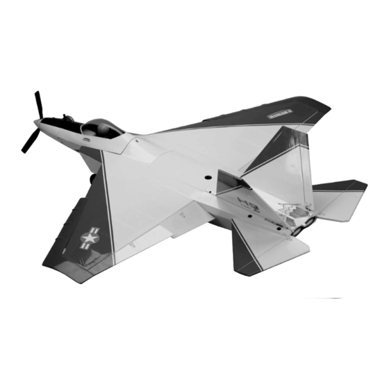
F-22 Raptor PTS
Specifications
Wingspan (with droops and tip extensions) .................................52 in (1320.8 mm)
Wingspan (without droops and tip extensions) ............................47.9 in (1216.66 mm)
Length ..........................................................................................50.3 in (1277.62 mm)
Wing Area (with droops and tip extensions) ................................731 sq in (47.16 sq dm)
Wing Area (without droops and tip extensions) ...........................675 sq in (43.55 sq dm)
Weight ..........................................................................................7.0–7.5 lb (3.18–3.40 kg)
Radio............................................................................................JR
Engine ..........................................................................................Evolution
Lockheed Martin and F-22 RAPTOR are either registered trademarks or trademarks of Lockheed Martin Corporation in the
USA and/or other countries, used under license by Horizon Hobby, Inc.
Assembly mAnuAl
®
Sport 600X 6-channel system (installed)
®
Engines Trainer Power System (installed)
™
Advertisement
Table of Contents

Related Manuals for Hangar 9 F-22 Raptor PTS


Summary of Contents for Hangar 9 F-22 Raptor PTS
- Page 1 F-22 Raptor PTS ™ Assembly mAnuAl Specifications Wingspan (with droops and tip extensions) .........52 in (1320.8 mm) Wingspan (without droops and tip extensions) ......47.9 in (1216.66 mm) Length ..................50.3 in (1277.62 mm) Wing Area (with droops and tip extensions) ........731 sq in (47.16 sq dm) Wing Area (without droops and tip extensions) ......675 sq in (43.55 sq dm)
-
Page 2: Table Of Contents
Section 12: Maintaining Your F-22 Raptor PTS ........ -
Page 3: Introduction
Sophisticated sensors, unmatched close-in dogfighting skills and undetectable at long range. The F-22 Raptor, the U.S. Air Force's newest aircraft, is the most advanced stealth fighter in aviation technology. With the F-22 Raptor PTS, beginners can learn to fly on a trainer that looks exciting. PTS ™... -
Page 4: Ultracote Covering Colors
• Long Reach Glow Plug Wrench (HAN2510) • 2-Cycle Sport Glow Plug (HAN3001) • Transmitter Stand (HAN2525) • Angle Pro Throw/Incidence Meter (HAN192) • Hangar 9 Straw Hat (HANP303) Additional Required Tools and Adhesives • Felt-tipped pen • Adjustable wrench •... -
Page 5: Warranty Period
Warranty Period Exclusive Warranty- Horizon Hobby, Inc., (Horizon) warranties that the Products purchased (the "Product") will be free from defects in materials and workmanship at the date of purchase by the Purchaser. Limited Warranty (a) This warranty is limited to the original Purchaser ("Purchaser") and is not transferable. REPAIR OR REPLACEMENT AS PROVIDED UNDER THIS WARRANTY IS THE EXCLUSIVE REMEDY OF THE PURCHASER. -
Page 6: Questions, Assistance, And Repairs
Questions, Assistance, and Repairs Your local hobby store and/or place of purchase cannot provide warranty support or repair. Once assembly, setup or use of the Product has been started, you must contact Horizon directly. This will enable Horizon to better answer your questions and service you in the event that you may need any assistance. -
Page 7: Safety, Precautions, And Warnings
Before Starting Assembly Before beginning the assembly of the F-22 Raptor PTS, remove each part from its bag for inspection. Closely inspect the fuselage, wing panels, rudder, and stabilizer for damage. If you find any damaged or missing parts, contact the place of purchase. -
Page 8: Section 1: Charging The Batteries
Section 1: Charging the Batteries Before starting the assembly of your F-22 Raptor PTS, Step 2 open the radio box and read the included instructions. Connect the charger lead from the charger to the lead Directions on the features, specifications, controls, coming from the switch harness as shown. -
Page 9: Section 2: Landing Gear Installation
Section 2: Landing Gear Installation Items Required Step 3 • Main landing gear (2) Press the gear into the slot in the fuselage. Use two • Nose landing gear landing gear straps and four #4 x 1/2" sheet metal screws to secure the landing gear to the fuselage. - Page 10 Section 2: Landing Gear Installation Step 5 Step 7 Slide the cockpit holding pin back and remove the cockpit Use the supplied hex wrench to tighten the screw in the from the fuselage. steering arm onto the nose gear wire. The screw will rest on the flat area of the nose gear wire.
-
Page 11: Section 3: Tail Installation
Section 3: Tail Installation Items Required Step 2 • Vertical stabilizer (left and right) Slide one of the horizontal stabilizers into the slot • Horizontal stabilizer (left and right) in the fuselage. • 4-40 x 3/4" hex head screw (4) •... - Page 12 Section 3: Tail Installation Step 4 Step 6 Slide the clevis retainer back on the clevis. Attach the Check the screws on the wheel collars holding the two clevis to the control horn, and then slide the clevis elevator linkages together.
- Page 13 Section 3: Tail Installation Step 8 Slide the clevis retainer back on the clevis. Attach the clevis to the outer hole of the control horn, and then slide the clevis retainer back onto the clevis to secure the clevis to the control horn.
-
Page 14: Section 4: Propeller Installation
Section 4: Propeller Installation Items Required Step 3 • Spinner w/backplate Slide the spinner backplate onto the engine shaft • Propeller • Spinner adapter w/screw Tools Required • Adjustable wrench • Hex wrench (included in kit) Step 1 Locate the spinner, spinner backplate, propeller, propeller adapter and adapter screw. - Page 15 Section 4: Propeller Installation Note: It is suggested to read the engine Step 5 instructions included with your F-22 Raptor Slide the washer onto the engine shaft and then thread the PTS at this time to learn more on the care spinner adapter onto the engine shaft.
-
Page 16: Section 5: Wing Installation
Section 5: Wing Installation Items Required Step 3 • Wing panel (left and right) Disconnect the clevis from the control horn and move • Wing tube (short) the linkage to the front position. Reconnect the clevis and slide the clevis retainer into place to prevent it from •... - Page 17 Section 5: Wing Installation Step 5 Step 7 Slide the tubes and wing panel into the holes in the Pass the aileron servo extension back and under the fuselage. Remove the tape from the aileron servo wing tube. The connector end of the extension then extension and pass it into the fuselage.
-
Page 18: Section 6: Centering The Control Surfaces
Section 6: Centering the Control Surfaces Ailerons Check to make sure the clevis is located in the outer hole of the control horn. If not, slide the clevis retainer forward, disconnect the clevis, connect it in the correct location, and slide the clevis retainer back into position. - Page 19 Section 6: Centering the Control Surfaces With the radio system on, thread the clevis until the Center the trim lever for the rudder on the transmitter. elevator is aligned with the stabilizer. Slide the clevis retainer onto the clevis to secure its location. With the radio system on, thread the clevis until the rudder is aligned with the fin.
-
Page 20: Section 7: Checking The Control Surface Directions
Section 7: Checking the Control Surface Directions Ailerons Elevator Turn on the transmitter, then the receiver. Move the aileron With the radio system still on, pull back on the elevator stick to the right, which is the input for a right turn. The control stick to give an up elevator input. - Page 21 Section 7: Checking the Control Surface Directions Rudder The final control surface direction to check is the rudder. With the radio system on, move the rudder stick to the right, this will make the plane turn right. The rudders should deflect to the right as well.
-
Page 22: Section 8: Checking The Control Throw Amounts
Section 8: Checking the Control Throw Amounts Your F-22 PTS airplane has the correct control throws Elevator Rate: 1 in (38mm) up and down pre-programmed into your transmitter. If necessary, Note: Measure the elevator throw at what follows is the method to check these appropriate the widest part of the elevator. -
Page 23: Section 9: Adjusting The Throttle
Section 9: Adjusting the Throttle With the radio system on, move the trim lever and throttle Move the trim lever up towards the top of the transmitter. lever towards the bottom of the transmitter. Look into the The barrel in the carburetor should have an opening of carburetor to check that the barrel is closed. -
Page 24: Section 10: Balancing Your F-22 Raptor
Section 10: Balancing Your F-22 Raptor In order for your F-22 Raptor PTS to fly correctly, you will Balanced Correctly need to check the balance of the plane with the fuel tank empty. This is done by supporting the aircraft either using your fingers or by using a balancing stand. - Page 25 F-22 Raptor PTS may not be balanced properly. Weights can be added to either the tail or the nose of your F-22 Raptor PTS if it does not balance properly. Stick-on weights available at your local hobby store are the easiest to use, and come in sizes that are easily placed on your plane.
-
Page 26: Section 11: Flight Preparations
When at the field, check to see if there is some form of frequency control in use. Usually there are clips each Fueling the F-22 Raptor PTS pilot will use signifying the channel their plane is flying Fill the fuel tank with the proper fuel. Fill the tank by on. -
Page 27: Section 12: Maintaining Your F-22 Raptor Pts
Clean Up use a T-pin to poke small holes in the covering in the area After a long flying session with your F-22 Raptor PTS, you where the control horn mounts, then saturate the area with will want to clean it up before loading it into your vehicle thin CA. -
Page 28: Section 13: Progressing With Your Flying Skills
Advanced Step 1 After you have mastered flying the F-22 Raptor PTS at Disconnect the flap linkage from the flap control horns. a faster pace, the next step is to reposition the flaps. Remove the linkage from the linkage stay. - Page 29 With the droops removed, your F-22 Raptor PTS is now an all-out aerobatic warbird. Have your instructor nearby for the first few flights. The F-22 Raptor PTS will now descend more quickly and land faster like a sport model. In the air, you can now do a variety of aerobatics such as rolls, loops, spins and snap rolls.
-
Page 30: Section 14: Adding Flap Servos
After you have graduated from the Progressive Training Step 1 System and are enjoying your F-22 Raptor PTS in its Remove the flap linkage from the aircraft. aerobatic mode, you can take it even a step further and add functional flaps. - Page 31 Section 14: Adding Flap Servos Step 3 Step 5 Remove the flap linkage stay from the wing. Be careful Install the recommended servo hardware (grommets and when removing the stay that you don't damage the wing. eyelets) supplied with the servo.
- Page 32 Section 14: Adding Flap Servos Step 7 Step 9 Place the aileron servo between the mounting blocks and Pass the servo lead through the flap opening and out of use a felt-tipped pen to mark the location of the four servo the end of the wing.
-
Page 33: Glossary Of Terms
Glossary of Terms Ailerons: Each side of this airplane has a hinged control Nose Gear: The part of the landing gear that is attached surface (aileron), located on the trailing edge of the to the nose of the fuselage. The nose gear is usually wing. -
Page 34: 2007 Official Ama National Model Aircraft Safety Code
2007 Official AMA National Model Aircraft Safety Code GENERAL 7) I will not operate models with pyrotechnics (any device that explodes, burns, or propels a projectile 1) I will not fly my model aircraft in sanctioned of any kind) including, but not limited to, rockets, events, air shows or model flying demonstrations until explosive bombs dropped from models, smoke it has been proven to be airworthy by having been... - Page 35 2007 Official AMA National Model Aircraft Safety Code 5) Flying sites separated by three miles or more Organized RC Racing Event are considered safe from site-to site interference, 10) An RC racing event, whether or not an AMA Rule even when both sites use the same frequencies. Any Book event, is one in which model aircraft compete circumstances under three miles separation require in flight over a prescribed course with the objective of...
- Page 36 © 2007 Horizon Hobby, Inc. 4105 Fieldstone Road Champaign, Illinois 61822 (877) 504-0233 www.horizonhobby.com 9890.1...
Need help?
Do you have a question about the F-22 Raptor PTS and is the answer not in the manual?
Questions and answers