
Related Manuals for Hangar 9 HAN2765


Summary of Contents for Hangar 9 HAN2765
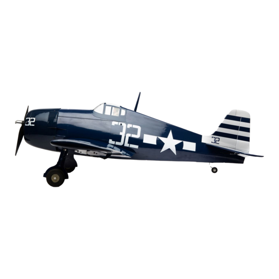
- Page 1 F6F-5 Hellcat 15cc Instruction Manual Bedienungsanleitung Manuel d’utilisation Manuale di Istruzioni...
- Page 2 SPECIFICATIONS • SPEZIFIKATIONEN • SPÉCIFICATIONS • SPECIFICHE 64.0 in (1628 mm) 698.3 sq in (45.1 dm2) Total/Totale 47.8 in (1213 mm) 9–10 lbs (4.08–4.54 kg) 2-Stroke Gas: 15cc–20cc, 4-Stroke gas/petrol: 20cc 2-Takt Benziner: 15cc–20cc, 4-Takt Benzin: 20 cc 2 temps Essence: 15cc–20cc, 4 temps essence: 20cc 2-Tempi Gas: 15cc–20cc, 4 tempi benzina: 20 cc Electric Power: Power 60, 470Kv Brushless Elektro Antrieb Power: Power 60, 470Kv Brushless...
- Page 3 Part # English Deutsch Français Italiano REPLACEMENT PARTS • ERSATZTEILE • PIÈCES DE RECHANGE • PEZZI DI RICAMBIO A HAN276501 Fuselage with Hatch Rumpf mit Haube Fuselage avec capot Fusoliera con portello B HAN276502 Left-Hand Wing with Aileron Linke Tragfl äche mit Querruder Aile gauche avec aileron Ala sinistra con alettone C HAN276503...
- Page 4 Tubo per carburante Tygon, 3 piedi, medio HAN116 Fuel Filler with “T” and Overfl ow Fitting Hangar 9 Tanknippel mit T Stück u. Überlauf Fitting Point de remplissage de carburant avec coupleur en T Bocchettone di riempimento carburante con SPM9530 Spektrum™...
- Page 5 Part # English Deutsch Français Italiano REQUIRED TOOLS • BENÖTIGTES WERKZEUG • OUTILS REQUIS • ATTREZZI NECESSARI C-clamp Schraubzwinge Serre joint Morsetto a C Drill Bohrer Mini-perceuse Trapano Drill bit: 1/16-inch, 5/64-inch, 3/32-inch, Bohrer: 1,5mm, 2mm, 2,5mm, 3mm, 3,5mm, 4mm, Forêt : 1,5mm, 2mm, 2,5mm, 3mm, 3,5mm, 4mm, Punte per trapano: 1,5mm, 2mm, 2,5mm, 3mm, 1/8-inch, 9/64-inch, 5/32-inch, 11/64-inch,...
-
Page 6: Before Starting Assembly
NOTICE Batteries Always follow the manufacturer’s instructions when using and disposing of any batteries. Mishandling of Li-Po All instructions, warranties and other collateral documents are subject to change at the sole discretion of Horizon batteries can result in fi re causing serious injury and damage. Hobby, LLC. -
Page 7: Vor Dem Zusammenbau
HINWEIS Propeller Halten Sie lose Gegenstände die sich im Propeller verfangen können weg vom Propeller. Dieses gilt auch für Kleidung Alle Anweisungen, Garantien und anderen zugehörigen Dokumente können im eigenen Ermessen von Horizon Hobby, oder andere Objekte wie zum Beispiel Stifte oder Schraubendreher. LLC. -
Page 8: Avant De Commencer L'assemblage
REMARQUE L’hélice Gardez éloignés tous les éléments qui pourraient être attrapés par l’hélice. Cela inclut les vêtements larges ou les La totalité des instructions, garanties et autres documents est sujette à modifi cation à la seule discrétion d’Horizon objets comme des outils par exemple. Gardez toujours vos mains à distance pour éviter tout cas de blessures. Hobby, LLC. -
Page 9: Precauzioni Per La Costruzione
AVVISO Elica Tenere gli oggetti liberi (vestiti, penne, cacciaviti, ecc.) lontano dall’elica, prima che vi restino impigliati. Bisogna fare Tutte le istruzioni, le garanzie e gli altri documenti pertinenti sono soggetti a cambiamenti a totale discrezione di attenzione anche con le mani perché c’è il rischio di ferirsi anche gravemente. Horizon Hobby, LLC. -
Page 10: Engine Selection
TRANSPORTATION AND STORAGE TRANSPORT UND LAGERUNG TRANSPORT ET STOCKAGE TRASPORTO E DEPOSITO Use the 3-view drawing at the back of this manual to Mit der Zeichnung aus drei Ansichten am Ende des Utilisez le schéma à 3 vues à l’arrière de ce manuel Fare riferimento al trittico riportato sul retro di questo determine the amount of space required to transport and Handbuchs lässt sich ermitteln, wie viel Platz zum... -
Page 11: Aileron Installation
AILERON INSTALLATION Apply epoxy to the area of the control horns that fi ts into the slots. Use enough epoxy so the control horns will be fully Separate the aileron slightly from the wing so the hinges are bonded to the fi xed surfaces. visible. -
Page 12: Aileron Servo Installation
11. Slide the hinges into position in the aileron with the T-pin 16. Check both the up and down movement of the hinges before resting against the edge of the control surface. proceeding. Repeat this section for the remaining aileron installation. ... - Page 13 21. Use a pin vise and 5/32-inch (2mm) drill bit to drill the holes 26. When attaching the linkage to the aileron servo arm, use the for the servo mounting screws. Make sure to harden the hole in the arm that is 5/8-inch (16mm) from the center of holes using the technique outlined in the previous steps.
- Page 14 31. Loosen the nuts, then place a drop of threadlock on the 36. Secure the landing gear using the screws prepared in the last linkage near the clevises. Tighten the nuts over the threadlock step. Make sure to place a drop of threadlock on each screw and against the clevises.
- Page 15 41. Use medium CA to glue the gear door mounts to the gear 46. Use a rotary tool and cut-off wheel to cut the length of door. the fi xed gear wire to 13/16-inches (20mm) Use a fl at fi le to make a fl...
- Page 16 51. Slide the strut through the gear door mounts. 56. Apply a drop of light machine oil to the axle. Slide the axle into the wheel. Slide a wheel collar on the axle, then secure it using an M3 x 4 setscrew and 1.5mm hex wrench. Make sure to use threadlock on the setscrew before installation.
- Page 17 RETRACT WHEEL WELL INSTALLATION 65. Lightly sand the outside of the wheel well where it contacts the wing with medium grit sandpaper. Use a paper towel and 60. Use a hobby knife and #11 blade to remove the covering from isopropyl alcohol to remove any oil or debris from the wheel the bottom of the wing to expose the opening for the retract.
- Page 18 70. Guide the lead from the retract along the side of the wheel 75. Check that there is a slight amount of toe-in (roughly well. The lead can be retrieved in the same area as the 1-degree). Adjustments can be made by loosening the two aileron extension.
- Page 19 Read through the following steps before installing the 85. Use an M3 x 5 button head screw to temporarily attach the gear doors. They must be aligned before the epoxy fully cures. gear door mounts to the gear doors using the pre-drilled holes in the gear door.
-
Page 20: Stabilizer Installation
90. Use a fl at fi le to make a fl at are for the fi rst 1/2-inch (12mm) 95. Check that the gear good closes fl at against the wing, and of the axle. that the door does not interfere with the operation of the retract. -
Page 21: Elevator Installation
99. Slide the wing into position on the fuselage. Guide the leads 104. Use a felt-tipped pen to transfer the fuselage outline onto the for the ailerons (and retracts) into the fuselage. bottom of the stabilizer. The wing may be a tight fit in the fuselage. Trim the fuselage as necessary so the wing fits without deforming the fuselage. -
Page 22: Fin Installation
109. Fit the joiner wire into the elevator halves. The elevator joiner 114. Use 15-minute epoxy to attach the blue elevator control horn wire must be fl ush with the leading edge of the elevator to the elevator. Use the control horn installation outlined for as shown. -
Page 23: Rudder And Elevator Servo Installation
119. Apply epoxy to the exposed wood on the bottom and front of 124. Install the rudder and elevator servos in the fuselage with the the fi n where it comes in contacts the fuselage. servo output towards the front of the fuselage. Make sure to prepare the holes as outlined in the aileron servo installation section of this manual. -
Page 24: Tail Wheel Installation
128. Attach the clevis to the rudder control horn. Loosen the nuts, 133. Remove the clevis from the 19 -inch (495mm) tail wheel then place a drop of threadlock on the linkage near the linkage. Slide the linkage into the fuselage. Attach the clevis clevises. - Page 25 138. Position the X-mount on the front of the motor box, aligning 142. Use an M4 x 20 socket head cap screw and M4 washer to it with the centerlines. Use a clamp to hold the mount while pull the M4 blind nuts into the back of the fi rewall. marking the mounting holes on the motor box with a felt- tipped pen.
-
Page 26: Gas Engine Installation
Motor installation other than the Power 60: 151. Install the battery tray in the fuselage by fi tting the notches at the front into the slots in the fi rewall. Apply a drop of The measurement from the fi rewall to the drive washer should threadlock on each of the M2 x 12 socket head cap screws. - Page 27 155. Use an M4 x 20 socket head cap screw and M4 washer to 160. Use a felt-tipped pen to mark the location for the four engine pull the M4 blind nuts into the back of the fi rewall. mounting bolts on the engine mount. ...
-
Page 28: Fuel Tank Installation
165. Secure the ignition module and receiver battery in the 170. A second clunk (included with your model) can also be fuselage. Use hook and loop tape and tie wraps to ensure installed to fi ll and drain the fuel tank. The procedure to their location. -
Page 29: Throttle Servo Installation
THROTTLE SERVO INSTALLATION 175. Place two hook and loop straps through the openings in the fuel tank tray. 180. Install the grommets and eyelets in the servos. Follow any instructions included with the servo. Install the servo in the ... -
Page 30: Cowling Installation
RECEIVER AND SWITCH HARNESS 190. Use medium grit sandpaper to lightly roughen the canopy 1/4-inch (6mm) around the perimeter of the canopy. Use INSTALLATION isopropyl alcohol and a paper towel to remove any debris of oils from the gluing surface of the canopy. 185. - Page 31 195. The dummy radial engine can be detailed using paint and 200. Using the paper as a guide, use a drill and 3/32-inch (2.5mm) the supplied grey aluminum tubing supplied with your model. drill bit to drill the holes for the cowl mounting screws. Make sure to test any paints on the pieces trimmed from Remove the tape from the cowl and the card stock once all the dummy radial to make sure they are compatible with the...
- Page 32 RADIO MAST INSTALLATION 205. Fit the antenna mast in the fi tting along the top of the fuselage. Remove the antenna for transport to avoid damage to it or the fuselage.
-
Page 33: Center Of Gravity
CENTER OF GRAVITY CONTROL THROWS An important part of preparing the aircraft for fl ight is properly balancing the model. The Center of Gravity range Turn on the transmitter and receiver of your model. Check the movement of the rudder using the transmitter. supplied here is a guideline based on testing. -
Page 34: Preflight Checklist
PREFLIGHT CHECKLIST DAILY FLIGHT CHECKS LIMITED WARRANTY Limitation of Liability HORIZON SHALL NOT BE LIABLE FOR SPECIAL, INDIRECT, • Charge the transmitter, receiver and motor battery for • Check the battery voltage of the transmitter battery. What this Warranty Covers INCIDENTAL OR CONSEQUENTIAL DAMAGES, LOSS OF your airplane. -
Page 35: Warranty And Service Contact Information
WARRANTY AND SERVICE CONTACT INFORMATION Inspection or Services Warranty Requirements If this Product needs to be inspected or serviced and is For Warranty consideration, you must include your compliant in the country you live and use the Product original sales receipt verifying the proof-of-purchase Country in, please use the Horizon Online Service Request date. - Page 36 MONTAGE DES QUERRUDERS Epoxid auf den Bereich der Steuerhörner auftragen, der in die Schlitze passt. Ausreichend Epoxid verwenden, sodass Das Querruder leicht vom der Tragfl äche trennen, sodass sich die Steuerhörner vollständig mit den festen Oberfl ächen die Aufhängungen sichtbar sind. Mit einem Filzstift eine verbinden.
-
Page 37: Montage Des Querruder-Servo
11. Die Aufhängungen auf dem Querruder in Position schieben, 16. Die Auf- und Abwärtsbewegung der Aufhängungen vor dem wobei der T-Stift gegen den Rand der Steuerfl äche liegt. Fortfahren überprüfen. Diesen Abschnitt zur Montage des verbleibenden Querruders wiederholen. MONTAGE DES QUERRUDER-SERVO 12. - Page 38 21. Mit einem Feilkloben und 2-mm-Bohrer (5/32 Zoll) Löcher 26. Beim Anbringen des Gestänges am Querruder-Servoarm die für die Befestigungsschrauben der Servoabdeckung bohren. Öffnung im Arm verwenden, die 16 mm (5/8 Zoll) von der Darauf achten, die Löcher anhand des in den vorherigen Mitte des Arms entfernt liegt.
- Page 39 31. Die Muttern lösen, dann einen Tropfen Gewindesicherung auf 36. Das Fahrwerk mit den im letzten Schritt vorbereiteten das Gestänge nahe dem Gabelkopf auftragen. Die Muttern Schrauben sichern. Vor dem Einsetzen der Schrauben über der Gewindesicherung und gegen die Gabelköpfe sicherstellen, einen Tropfen Gewindesicherung auf die festziehen.
- Page 40 41. Mittlere CA-Klebstoff verwenden, um die Halterungen der 46. Mit einem Rotationswerkzeug und einer Trennscheibe das Fahrwerkklappe an der Fahrwerkklappe zu befestigen. Kabel des starren Fahrwerks auf eine Länge von 20 mm (13/16 Zoll) schneiden. Mit einer Flachfeile einen fl achen Bereich entlang der Vorderkante des verbleibenden Fahrwerk- Kabels schaffen.
- Page 41 51. Die Strebe durch die Fahrwerkklappen-Halterung schieben. 56. Einen Tropfen leichtes Maschinenöl auf die Achse auftragen. Die Achse in das Rad schieben. Eine Anschlaghülse auf die Achse schieben, diese dann mit einer M3 x 4 Feststellschraube und einem 1,5 mm Sechskant sichern. Sicherstellen, Gewindesicherung vor der Montage auf der Feststellschraube aufzutragen.
- Page 42 MONTAGE DES EINZIEHBAREN 65. Die Außenseite des Fahrwerkschafts dort mit Sandpapier mittlerer Körnung leicht schleifen, wo er die Tragfl äche FAHRWERKSCHAFTS berührt. Mit einem Papiertuch und Isopropylalkohol Öl- oder Schmutzrückstände vom Fahrwerkschaft entfernen. 60. Mit einem Hobbymesser und einer Nr. 11-Klinge die Abdeckung von der Unterseite der Tragfl...
- Page 43 69. Die Achse auf der Verstrebung positionieren, so dass sie 74. Das Rad auf die Achse schieben. Die mit der 140 mm (5 Zoll) von der auf der Strebe befi ndlichen Hülse Einfahrvorrichtung mitgelieferte Anschlaghülse auf der sitzt. Das ist die ungefähre Position für die Achse. Achse positionieren.
- Page 44 79. Sicherstellen, eine linke und rechte Fahrwerkklappe 84. Mit einem Feilkloben und einem 3 mm (1/8 Zoll) Bohrer vier vorzubereiten. Befestigungslöcher in die Fahrwerkklappe bohren und die auf dem Foto angegebenen Maße als Vorlage nutzen. Die nachfolgenden Schritte vor der Montage der 85.
- Page 45 89. Die Einfahrvorrichtung mit der beigelegten Hardware an der 94. Prüfen, ob eine leichte Vorspur (etwa 1 Grad) besteht. Tragfl äche befestigen. Vor dem Einsetzen der Schrauben in Anpassungen können durch das Lösen der zwei der Einfahrvorrichtung einen Tropfen Gewindesicherung auf Feststellschrauben mit einem 1,5 mm Sechskant auf jede Schraube auftragen.
- Page 46 97. Die Kanzelabdeckung an der Rückseite vom Rumpf abheben. 102. 2–3 Meter (8–10 Fuß) zurücktreten und überprüfen, ob Die Abdeckung zurückziehen und vom Rumpf entfernen. An der Stabilisator mit der Tragfl äche ausgerichtet ist. Den einem sicheren Ort ablegen. Stabilisatorsattel am Rumpf leicht schleifen, um etwaige Fehlausrichtungen zu korrigieren.
-
Page 47: Montage Des Höhenruders
107. Den Stabilisator wieder auf dem Rumpf positionieren und 112. Mit einem Zahnstocher das Epoxid auf den Stabilisator die Ausrichtung überprüfen. Mit einem Papiertuch und etwas auftragen, wo er das Verbinderkabel berührt. Isopropylalkohol überschüssiges Epoxid von Rumpf und Stabilisator entfernen, bevor das Epoxid vollständig aushärtet. Das Epoxid muss vor dem Fortfahren vollständig ausgehärtet sein. - Page 48 MONTAGE DES SEITENLEITWERKS 122. Das Seitenruder an das Seitenleitwerk anpassen. Das Seitenruder mit dem Seitenleitwerk ausrichten, damit es 117. Das Seitenleitwerk am Rumpf anpassen. Mit einem Winkel die sich ohne Beeinträchtigungen frei bewegen kann. Die Ausrichtung des Seitenleitwerks auf dem Stabilisator prüfen. Aufhängungen verkleben und dabei das bereits beschriebene Die Unterseite des Seitenleitwerks bei Bedarf leicht schleifen, Verfahren für die Querruder-Aufhängungen befolgen.
-
Page 49: Montage Des Spornrads
MONTAGE DES SPORNRADS 127. Das weiße Seitenruder-Steuerhorn kann nun mit 15-minütigem Epoxid am Seitenruder gesichert werden. 131. Den Spornrad-Steuerarm vom Spornrad-Kabel entfernen. Den Das Seitenruder-Steuerhorn so positionieren, dass es in fl achen Bereich beachten, wo die Schraube am Spornrad- einem Winkel nach zur Unterseite des Rumpfs weist und mit Kabel gesichert ist. -
Page 50: Montage Des Elektromotors
136. Mit Kanzelkleber die Spornrad-Abdeckung am Rumpf 140. Die Befestigungsplatte auf dem Brandschott platzieren. befestigen. Mit einem Klebeband mit geringer Klebekraft Mit Klebeband geringer Klebekraft die Vorlage in Position die Abdeckung in Position halten, bis der Kleber vollständig halten. Mit einem 2 mm (5/32 Zoll) Bohrer vier Löcher in den ausgehärtet ist. - Page 51 145. Mit einem Nr. 2 Kreuzschlitzschraubendreher die X-Halterung 149. Mit 5-minütigem Epoxid das Klettband an der Akku-Halterung auf der Rückseite des Motors anbringen. Einen Tropfen befestigen. Gewindesicherung auf den Schrauben vor dem Sichern der X-Halterung am Motor auftragen. Die Sicherheitshinweise auf dem Akku mit dem Klettband nicht verdecken.
- Page 52 153. Die Befestigungsplatte auf dem Brandschott platzieren. 158. Mit einem Nr. 2-Kreuzschlitzschraubendreher die Schrauben Mit Klebeband geringer Klebekraft die Vorlage in Position festziehen, sobald beide Halterung korrekt auf dem halten. Mit einem 2 mm (5/32 Zoll) Bohrer vier Löcher in den Brandschott positioniert sind. Brandschott bohren, um den Motorkasten anzubringen.
- Page 53 MONTAGE DES KRAFTSTOFFBEHÄLTERS 163. Das Gas-Gestänge durch die Öffnung im Brandschott schieben. Den Motor zwischen die Motorhalterungen 168. Die Verschlussbaugruppe vorbereiten, indem kleine Mengen einpassen. Eine M4-Unterlegscheibe auf die M4 x 30 Lot wie abgebildet auf das Ende der Rohre platziert werden. Maschinenschrauben legen, dann die Schrauben durch Dadurch werden die Kraftstoffl...
- Page 54 173. Eine 127 mm (5 Zoll) Kraftstoffl eitung an der Füllleitung 178. Die Kraftstoffl eitungen am Vergaser anschließen. des Kraftstoffbehälters sichern. Die Überlaufl eitung kann Sicherstellen, einen Kraftstoff-Filter zu verwenden, um ein an der Entlüftung sowie an der verbleibenden Leitung zur Eindringen von Schmutz in den Motor zu verhindern. Pendelleitung angebracht werden, die am Ende am Vergaser angebracht wird.
-
Page 55: Montage Der Motorhaube
183. Mit einem Seitenschneider das Gas-Gestänge trimmen, damit Montage des Gasmotor-Zündschalters es den Betrieb von Gas nicht beeinträchtigen kann. 188. Die Abdeckung von der Rumpfseite mit einem Hobbymesser und einer Nr. 11 Klinge entfernen. Den Zündschalter mit der mit dem Schalter bereitgestellten Hardware befestigen. Die Leitung vom Zünd-Akku am Schalter sichern. - Page 56 Trimmen zur Montage des Elektromotors 198. Vier 12 mm (1/2 Zoll) breite Streifen aus Karton schneiden. Mit Klebeband geringer Klebekraft den Karton am Rumpf 193. Mit einer Hobbyschere das Material zwischen den unteren anbringen und anzeichnen, wo sich die Motorhauben- Zylindern entfernen. Mit Sandpapier mittlerer Körnung Ecken Halterungslaschen auf dem Brandschott befi...
- Page 57 203. Die Motorhaube mit vier M3 x 10 Blechschrauben am Rumpf befestigen. Die Schrauben mit einem Nr. 2 Kreuzschlitzschraubendreher festziehen. Vorsichtig beim Trimmen der Motorhaube für die Nadelventilverlängerung vorgehen. Mit einem kleinen Loch beginnen und langsam vergrößern, um zu garantieren, dass es korrekt positioniert ist. 204.
-
Page 58: Der Schwerpunkt
DER SCHWERPUNKT RUDERAUSSCHLAG Ein wichtiger Teil bei der Vorbereitung des Flugzeugs für den Flug ist das ordnungsgemäße Ausbalancieren des Den Sender und Empfänger des Modells einschalten. Die Bewegung des Seitenruders mit der Fernsteuerung Modells. Der hier aufgeführte Schwerpunktbereich dient basierend auf Tests als Richtlinie. Abweichungen von prüfen. -
Page 59: Täglicher Flug Check
VORFLUGKONTROLLE TÄGLICHER FLUG CHECK GARANTIE UND SERVICE Horizon behält sich vor, alle eingesetzten Komponenten zu prüfen, die in den Garantiefall einbezogen werden INFORMATIONEN • Laden Sie den Sender- ,Empfänger- und Zündakku • Überprüfen Sie die Spannung des Senderakkus. können. -
Page 60: Garantie Und Service Kontaktinformationen
Sicherheitshinweise Fragen, Hilfe und Reparaturen Bitte legen Sie dem Produkt einen Kaufbeleg bei, sowie ACHTUNG: Kostenpfl ichtige Reparaturen nehmen wir Dieses ist ein hochwertiges Hobby Produkt und kein Ihr lokaler Fachhändler und die Verkaufstelle können eine ausführliche Fehlerbeschreibung und eine Liste aller nur für Elektronik und Motoren vor. - Page 61 INSTALLATION DE L’AILERON Appliquez de la colle époxy sur la partie des renvois de commande qui rentre dans les fentes. Utilisez suffi samment Séparez doucement l’aileron de l’aile afi n de rendre les de colle époxy afi n que les renvois de commande soient charnières visibles.
-
Page 62: Installation Du Servo De L'aileron
11. Glissez les charnières en place dans l’aileron, l’épingle en T 16. Vérifi ez le mouvement ascendant et descendant des en appui contre le bord de la surface de commande. charnières avant de continuer. Répétez cette partie pour l’installation des ailerons restants. ... - Page 63 21. Utilisez un porte-foret et une mèche de 2 mm (5/32 po) pour 26. Lorsque vous fi xez la tringlerie au bras du servo de l’aileron, percer les trous pour les vis de montage du servo. Assurez- utilisez le trou dans le bras qui se trouve à 16 mm (5/8 po) du vous de bien durcir les trous à...
- Page 64 31. Desserrez les écrous, puis appliquez une goutte de frein-fi let 36. Fixez le train d’atterrissage grâce aux vis préparée lors de sur la tringlerie, à proximité des manilles. Serrez les écrous l’étape précédente. Assurez-vous d’appliquer une goutte de sur le frein-fi let et contre les manille. frein-fi...
- Page 65 41. Utilisez une CA moyenne pour coller les supports de la trappe 46. Utilisez un outil rotatif et couper la roue pour couper la du train à la trappe du train. longueur du câble du train fi xe de 20 mm (13/16 po). Utilisez une lime plate pour créer une surface plate le long de l’extrémité...
- Page 66 51. Placez la jambe dans le support de la trappe du train. 56. Appliquez une goutte d’huile de machine sur l’axe. Faites coulisser l’axe dans la roue. Placez une bague sur l’axe, puis sécurisez-la avec quatre vis de fi xation et une clé à six pans 1,5 mm.
- Page 67 INSTALLATION DU PASSAGE DE ROUE DE 65. À l’aide d’un papier abrasif de grain moyen, poncez légèrement l’extérieur du passage de roue où il touche l’aile. RENTRÉE Imprégnez du papier absorbant d’alcool isopropylique pour enlever toute trace d’huile ou d’impuretés sur le passage de 60.
- Page 68 70. Faites passer le fi l du système de rentrée dans le côté du 75. Vérifi ez la présence d’un léger pincement (environ 1 degré). passage de roue. Le fi l peut être récupéré dans la même zone Des ajustements peuvent être effectués en desserrant les que la rallonge de l’aileron.
- Page 69 Lisez toutes les étapes suivantes avant d’installer 85. Utilisez une vis à tête bombée M3 x 5 pour fi xer les trappes du train. Elles doivent être alignées avant temporairement les supports de la trappe du train aux trappes que la colle époxy ne sèche entièrement. du train en utilisant les trous pré-percés dans la trappe du train.
-
Page 70: Installation Du Stabilisateur
90. Utilisez une lime plate pour créer une surface plate sur les 95. Vérifi ez que la trappe du train se ferme bien contre l’aile, premiers 12 mm (1/2 po) de l’axe. et que la trappe n’empêche pas le système de rentrée de fonctionner correctement. - Page 71 99. Faites glisser l’aile en position sur le fuselage. Guidez les fi ls 104. Utilisez un stylo-feutre pour transférer le contour du fuselage pour les ailerons (et le système de rentrée) dans le fuselage. sur le bas du stabilisateur. Il peut être difficile d’ajuster l’aile dans le fuselage. Compensez le fuselage, si nécessaire pour que l’aile s’ajuste sans déformer le fuselage.
-
Page 72: Installation De La Dérive
109. Insérez la tige dans les deux parties de l’élévateur. La tige 114. Utilisez de la colle époxy 15 minutes pour fi xer les renvois de l’élévateur doit être alignée avec le bord d’attaque de de commande bleus de l’élévateur dans l’élévateur. Utilisez l’élévateur comme dans l’illustration ci-contre. - Page 73 119. Appliquez de la colle époxy sur la surface de bois exposée en 124. Installez les servos du gouvernail et de l’élévateur dans le haut et à l’avant de la dérive, où elle entre en contact avec le fuselage, la sortie du servo dirigée vers l’avant du fuselage. fuselage.
-
Page 74: Installation De La Roue De Queue
128. Attachez la manille au renvoi de commande de la gouverne. 133. Retirez une manille de la tringlerie de la roue de queue de Desserrez les écrous, puis appliquez une goutte de frein-fi let 495 mm (19 po). Glissez la tringlerie dans le fuselage. sur la tringlerie, à... - Page 75 138. Positionnez le support en X à l’avant du boîtier du moteur, en 142. Utilisez une vis d’assemblage creuse M4 x 20 et une rondelle l’alignant avec les lignes centrales. Utilisez une pince pour M4 pour tirer les écrous borgnes M4 à l’arrière du pare-feu. maintenir le support tout en marquant les trous de montage sur le boîtier du moteur avec un stylo-feutre.
-
Page 76: Installation Du Moteur À Essence
Installation d’un autre moteur que le Power 60 : 151. Installez la tablette de batterie dans le fuselage, en ajustant les encoches à l’avant des fentes du pare-feu. Appliquez Les mesures du pare-feu à la rondelle d’entraînement doivent une goutte de frein-fi let sur chaque vis d’assemblage mesurer 149 mm (5 po). - Page 77 155. Utilisez une vis d’assemblage creuse M4 x 20 et une rondelle 160. Utilisez un stylo-feutre pour marquer l’emplacement destiné M4 pour tirer les écrous borgnes M4 à l’arrière du pare-feu. aux quatre vis de montage du moteur sur le support de montage du moteur. ...
- Page 78 165. Fixez le module d’allumage et la batterie du récepteur dans le 170. Un second plongeur (inclus avec votre maquette) peut fuselage. Utilisez une bande velcro et des colliers de serrage également être installé pour remplir et vider le réservoir de pour assurer l’emplacement.
-
Page 79: Installation Du Servo Des Gaz
INSTALLATION DU SERVO DES GAZ 175. Passez deux sangles velcro dans les ouvertures dans la tablette du réservoir de carburant. 180. Installez les passe-fi ls et les œillets dans les servos. Suivez toutes les instructions fournies avec le servo. Installez le ... -
Page 80: Installation Du Capot
INSTALLATION DU FAISCEAU DU COMMUTATEUR 190. Utilisez un papier abrasif à grains moyens pour rendre légèrement rugueux la verrière à 6 mm (1/4 po) autour du ET DU RÉCEPTEUR périmètre de la verrière. Imprégnez du papier absorbant d’alcool isopropylique pour enlever toute trace d’huile à la 185. - Page 81 195. Le faux moteur en étoile peut être détaillé en utilisant de la 200. En vous guidant à l’aide du papier, utilisez une perceuse et peinture et la tubulure grise en aluminium incluse avec votre une mèche de 2,5 mm (3/32 po) pour percer les trous pour maquette.
- Page 82 INSTALLATION DU MÂT D’ANTENNE 205. Placez le mât d’antenne dans le raccord le long du haut du fuselage. Retirez l’antenne pour le transport pour éviter de l’endommager ou d’endommager le fuselage.
-
Page 83: Centre De Gravité
CENTRE DE GRAVITÉ DÉBATTEMENTS Le maintien de la maquette en équilibre est une étape importante de la préparation du vol de l’avion. La plage du Mettez l’émetteur et le récepteur sous tension. Contrôlez les mouvements de la dérive en utilisant votre émetteur. centre de gravité... -
Page 84: Checklist D'avant Vol
CHECKLIST D’AVANT VOL CONTRÔLES SYSTÉMATIQUES GARANTIE ET RÉPARATIONS Limitation des dommages Horizon ne saurait être tenu pour responsable de • Chargez la batterie de votre émetteur, de réception • Contrôlez la tension de la batterie de l’émetteur. Durée de la garantie dommages conséquents directs ou indirects, de pertes et d’allumage. -
Page 85: Coordonnées De Garantie Et Réparations
Questions, assistance et réparations Garantie et réparations ATTENTION: Nous n’effectuons de réparations Votre revendeur spécialisé local et le point de vente Les demandes en garantie seront uniquement traitées payantes que pour les composants électroniques ne peuvent effectuer une estimation d’éligibilité à en présence d’une preuve d’achat originale émanant et les moteurs. - Page 86 INSTALLAZIONE DELL’ALETTONE Applicare colla epossidica nell’area delle squadrette da inserire nelle fessure. Utilizzare una quantità di colla Separare leggermente l’alettone dall’ala in modo che le epossidica suffi ciente a fare in modo che le squadrette siano cerniere siano visibili. Utilizzare un pennarello per segnare il completamente fi...
-
Page 87: Installazione Del Servo Dell'alettone
11. Far scivolare le cerniere in posizione sull’alettone con lo spillo 16. Prima di procedere, controllare il movimento delle cerniere a T appoggiato contro il bordo della superfi cie di controllo. verso l’alto e verso il basso. Ripetere questa procedura per l’installazione dell’altro alettone. - Page 88 21. Utilizzare un minitrapano e una punta da 2 mm (5/32 26. Per applicare la biella di collegamento al braccio del servo pollici) per realizzare i fori per le viti di montaggio del servo. dell’alettone, usare il foro del braccio che si trova a 16 mm Rinforzare i fori usando la tecnica illustrata nei passaggi (5/8 pollici) dal centro dello stesso.
- Page 89 31. Allentare i dadi e applicare una goccia di frenafi letti sulla 36. Fissare il carrello di atterraggio utilizzando le viti preparate al biella di collegamento vicino alle forcelle. Serrare i dadi sul passaggio precedente. Applicare una goccia di frenafi letti su frenafi...
- Page 90 41. Usare colla cianoacrilica a media densità per fi ssare i supporti 46. Utilizzare un trapano e un disco da taglio per tagliare il cavo del portello del carrello di atterraggio al portello stesso. del carrello di atterraggio fi sso a una lunghezza di 20 mm (13/16 pollici).
- Page 91 51. Inserire la gamba nei supporti del portello del carrello di 56. Applicare una goccia di olio per macchine leggero sull’assale. atterraggio. Infi lare l’assale nella ruota. Inserire un collarino per ruota sull’assale e fi ssarlo con un grano di pressione M3 x 4 e una chiave esagonale da 1,5 mm.
- Page 92 INSTALLAZIONE DELL’ALLOGGIAMENTO DELLA 65. Levigare leggermente con carta abrasiva a grana media l’esterno dell’alloggiamento della ruota nel punto di contatto RUOTA RETRATTILE con l’ala. Con un panno di carta e alcool isopropilico, rimuovere eventuali oli e residui dall’alloggiamento. 60. Utilizzare un taglierino e una lama #11 per rimuovere il rivestimento dalla parte inferiore dell’ala ed esporre l’apertura dell’elemento retrattile.
- Page 93 70. Far scorrere il cavo dell’elemento retrattile lungo il fi anco 75. Controllare che ci sia un piccolo angolo di convergenza dell’alloggiamento della ruota. Il cavo fuoriesce in prossimità (1 grado circa). Le regolazioni possono essere effettuate della prolunga dell’alettone. svitando i due grani di pressione sulla gamba, vicino al supporto, con una chiave esagonale da 1,5 mm.
- Page 94 Leggere i passaggi successivi prima di installare i 85. Utilizzare una vite a testa tonda M3 x 5 per fi ssare portelloni del carrello di atterraggio. È necessario allinearli temporaneamente i supporti del portello del carrello di prima che la colla epossidica si asciughi completamente. atterraggio al portello stesso sfruttando i fori realizzati in precedenza.
- Page 95 90. Usare una lima piatta per realizzare un’area piana sui primi 95. Verifi care che il carrello si chiuda bene contro l’ala e che il 12 mm (1/2 pollici) dell’assale. portello non interferisca con il funzionamento dell’elemento retrattile. Effettuata la regolazione, fi ssare il portello del carrello di atterraggio alla gamba utilizzando quattro grani M3 x 4 e una chiave esagonale da 1,5 mm.
- Page 96 99. Far scorrere l’ala in posizione sulla fusoliera. Inserire i cavi 104. Usare un pennarello per tracciare la sagoma della fusoliera per gli alettoni (e gli elementi retrattili) all’interno della sulla parte inferiore dello stabilizzatore. fusoliera. L’ala deve aderire perfettamente alla fusoliera. Se necessario, tagliare la fusoliera affinché...
- Page 97 109. Inserire il cavo di giunzione nelle due metà dell’elevatore. Il 114. Utilizzare colla epossidica “15 minuti” per fi ssare la cavo di giunzione deve essere a fi lo con il bordo di attacco squadretta blu dell’elevatore all’elevatore stesso. Per dell’elevatore come illustrato.
-
Page 98: Installazione Del Timone
119. Applicare la colla epossidica sul legno esposto alla base 124. Montare i servo dell’elevatore e del timone nella fusoliera con e nella parte anteriore dell’aletta nel punto in cui entra in l’uscita rivolta verso la parte anteriore della stessa. Preparare contatto con la fusoliera. -
Page 99: Installazione Del Ruotino Di Coda
128. Fissare la forcella alla squadretta del timone. Allentare i dadi e 133. Rimuovere la forcella dalla biella di collegamento del applicare una goccia di frenafi letti sulla biella di collegamento ruotino di coda da 495 mm (19 pollici). Inserire la biella di vicino alle forcelle. - Page 100 138. Posizionare il supporto a X sulla parte anteriore del vano 142. Utilizzare una vite a brugola M4 x 20 e una rondella M4 per motore, allineandolo agli assi. Utilizzare un morsetto tirare i dadi a calotta M4 nel retro della paratia tagliafi amma. per fi...
- Page 101 Installazione di motori diversi dal Power 60: 151. Installare il supporto della batteria nella fusoliera inserendo gli intagli sulla parte anteriore nelle fessure della paratia La distanza tra la paratia tagliafi amma e il disco di trasmissione tagliafi amma. Applicare una goccia di frenafi letti su ognuna deve essere di 149 mm (5 pollici).
- Page 102 155. Utilizzare una vite a brugola M4 x 20 e una rondella M4 per 160. Usare un pennarello per segnare la posizione dei quattro tirare i dadi a calotta M4 nel retro della paratia tagliafi amma. bulloni di montaggio del motore sul supporto del motore. ...
- Page 103 165. Fissare il modulo di accensione e la batteria del ricevitore 170. È possibile installare un secondo fi ltro (incluso nel modello) nella fusoliera. Utilizzare del nastro di velcro e delle fascette per riempire e svuotare il serbatoio. La procedura per per mantenerli in posizione.
- Page 104 INSTALLAZIONE DEL SERVO DEL GAS 175. Infi lare due fascette a strappo nelle aperture del supporto del serbatoio. 180. Installare le guarnizioni e gli occhielli per i servo. Seguire eventuali istruzioni fornite con il servo. Inserire il servo Applicare una piccola quantità di colla epossidica nella fusoliera con l’uscita del servo rivolta verso l’esterno “5 minuti”...
-
Page 105: Installazione Della Cappottatura
INSTALLAZIONE DEL CABLAGGIO DEL 190. Utilizzare della carta abrasiva a grana media per irruvidire leggermente la capottina per 6 mm (1/4 pollici) lungo il RICEVITORE E DELL’INTERRUTTORE suo perimetro. Con un panno di carta e alcool isopropilico, rimuovere eventuali residui di oli dalla superfi cie di 185. - Page 106 195. Il motore radiale posticcio può essere rifi nito con della vernice 200. Utilizzando il cartoncino come guida, realizzare i fori delle viti e i tubi grigi in alluminio in dotazione insieme al modello. di montaggio della cappottatura con un trapano e una punta Testare ogni vernice sulle parti tagliate del motore radiale da 2,5 mm (3/32 pollici).
- Page 107 INSTALLAZIONE DELL’ANTENNA RADIO 205. Inserire l’antenna radio nell’apposito alloggiamento nella parte superiore della fusoliera. Durante il trasporto, rimuovere l’antenna per evitare di danneggiare l’antenna stessa o la fusoliera. F6F-5 Hellcat 15cc...
-
Page 108: Corse Dei Comandi
BARICENTRO CORSE DEI COMANDI Per preparare l’aeromodello al volo, è importante effettuare un accurato bilanciamento. La gamma di valori qui indicata Accendere trasmittente e ricevente del modello. Verifi care il movimento del timone agendo sulla trasmittente. per il baricentro è il risultato dei test effettuati. È possibile adottare impostazioni diverse da quelle qui riportate e Quando si sposta lo stick verso destra il timone deve andare a destra. -
Page 109: Lista Dei Controlli Prima Del Volo
LISTA DEI CONTROLLI PRIMA DEL VOLO CONTROLLI DI VOLO GIORNALIERI GARANZIA Questa garanzia non copre danni dovuti ad un’installazione errata, ad un funzionamento errato, • Caricare le batterie di trasmettitore, ricevitore • Controllare la tensione della batteria del trasmettitore. Periodo di garanzia ad una manutenzione o un tentativo di riparazione e accensione motore usando i caricabatterie... -
Page 110: Contatti Per La Garanzia E L'assistenza
Domande, assistenza e riparazioni Garanzia e riparazione ATTENZIONE: Le riparazioni a pagamento sono Il vostro negozio locale e/o luogo di acquisto non Le richieste in garanzia verranno elaborate solo se è disponibili solo sull’elettronica e sui motori. Le possono fornire garanzie di assistenza o riparazione presente una prova d’acquisto in originale proveniente riparazioni a livello meccanico, soprattutto per senza previo colloquio con Horizon. - Page 111 8 inches (203mm) 47.8 inches (1213mm) 14 inches (356mm) 64.0 in (1628 mm) 64 inches (1628mm) 698.3 sq in (45.1 dm2) Total/Totale 47.8 in (1213 mm) 9–10 lbs (4.08–4.54 kg) 2-Stroke Gas: 15cc–20cc, 4-Stroke gas/petrol: 20cc 2-Takt Benziner: 15cc–20cc, 4-Takt Benzin: 20 cc 2 temps Essence: 15cc–20cc, 4 temps essence: 20cc 2-Tempi Gas: 15cc–20cc, 4 tempi benzina: 20 cc Electric Power: Power 60, 470Kv Brushless...
- Page 112 © 2018 Horizon Hobby, LLC. Hangar 9, Evolution, AS3X, EC5 and the Horizon Hobby logo are trademarks or registered trademarks of Horizon Hobby, LLC. The Spektrum trademark is used with permission of Bachmann Industries, Inc. All other trademarks, service marks and logos are the property of their respective owners.
Need help?
Do you have a question about the HAN2765 and is the answer not in the manual?
Questions and answers