Table of Contents
Advertisement
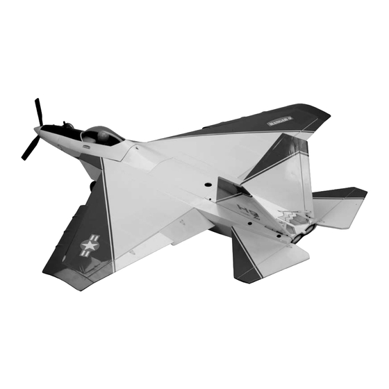
F-22 Raptor ARF
Specifications
Wingspan (with droops and tip extensions) .................................52 in (1320.8 mm)
Wingspan (without droops and tip extensions) ............................47.9 in (1216.66 mm)
Length ..........................................................................................50.3 in (1277.62 mm)
Wing Area (with droops and tip extensions) ................................731 sq in (47.16 sq dm)
Wing Area (without droops and tip extensions) ...........................675 sq in (43.55 sq dm)
Weight ..........................................................................................7.0–7.5 lb (3.18–3.40 kg)
Lockheed Martin and F-22 RAPTOR are either registered trademarks or trademarks of Lockheed Martin Corporation
in the USA and/or other countries, used under license by Horizon Hobby, Inc.
Assembly mAnuAl
Advertisement
Table of Contents

Subscribe to Our Youtube Channel
Related Manuals for Hangar 9 F-22 Raptor


Summary of Contents for Hangar 9 F-22 Raptor
- Page 1 Wing Area (without droops and tip extensions) ......675 sq in (43.55 sq dm) Weight ..................7.0–7.5 lb (3.18–3.40 kg) Lockheed Martin and F-22 RAPTOR are either registered trademarks or trademarks of Lockheed Martin Corporation in the USA and/or other countries, used under license by Horizon Hobby, Inc.
-
Page 2: Table Of Contents
Section 17: Maintaining Your F-22 Raptor ARF ........ -
Page 3: Introduction
, the U.S. Air Force's newest aircraft, is the most advanced stealth fighter in aviation technology. With the F-22 Raptor ARF, beginners can learn to fly on a trainer that looks exciting. This revolutionary trainer sports red plastic NACA droops and wing tip extensions that attach to the outer edge of the wing to provide extra stability. -
Page 4: Ultracote Covering Colors
• Long Reach Glow Plug Wrench (HAN2510) • 2-Cycle Sport Glow Plug (HAN3001) • Transmitter Stand (HAN2525) • Angle Pro Throw/Incidence Meter (HAN192) • Hangar 9 Straw Hat (HANP303) • Sealing Iron ( HAN101) • Sealing Iron Sock (HAN141) • Heat Gun (HAN100) •... -
Page 5: Radio And Power Systems Requirements
Radio and Power Systems Requirements • 4-channel radio system (minimum) w/receiver • ST47 Servo (JSP20050) (5) or equivalent • 6-inch Servo Lead Extension (JRPA095) (2) • Long Servo Arm (JRPA212) (2) • Y-Harness (JSP98020) • Receiver Battery (JSP91010) • Receiver (JSP30060) •... -
Page 6: Limited Warranty
Limited Warranty (a) This warranty is limited to the original Purchaser ("Purchaser") and is not transferable. REPAIR OR REPLACEMENT AS PROVIDED UNDER THIS WARRANTY IS THE EXCLUSIVE REMEDY OF THE PURCHASER. This warranty covers only those Products purchased from an authorized Horizon dealer. Third party transactions are not covered by this warranty. Proof of purchase is required for warranty claims. -
Page 7: Questions, Assistance, And Repairs
Questions, Assistance, and Repairs Your local hobby store and/or place of purchase cannot provide warranty support or repair. Once assembly, setup or use of the Product has been started, you must contact Horizon directly. This will enable Horizon to better answer your questions and service you in the event that you may need any assistance. -
Page 8: Safety, Precautions, And Warnings
Before Starting Assembly Before beginning the assembly of the F-22 Raptor ARF, remove each part from its bag for inspection. Closely inspect the fuselage, wing panels, rudder, and stabilizer for damage. If you find any damaged or missing parts, contact the place of purchase. -
Page 9: Section 1: Aileron Servo Installation
Section 1: Aileron Servo Installation Items Required Step 2 • Wing (left and right) Attach a 6-inch (152mm) servo extension to the •#2 x 3/8-inch screw (8) servo lead. Use either string or a commercially available connector to prevent the two from •... - Page 10 Section 1: Aileron Servo Installation Note: Before mounting the aileron servo, Step 4 make sure the servo arm is installed correctly Locate two 3/8 x 3/4 x 3/4-inch (9.5 x 19 x 19mm) servo on the servo. This is done by moving the mounting blocks.
- Page 11 Section 1: Aileron Servo Installation Step 8 Step 9 Tie one of the wheel collars to a 24-inch (600mm) length Tie the string to the servo extension for the aileron servo. of string. Guide the wheel collar (and string) into the Carefully pull the string and extension through the wing.
- Page 12 Section 1: Aileron Servo Installation Step 11 Step 13 Locate a 4 -inch (121mm) pushrod wire, clevis and Double-check, using the radio system, that the aileron clevis retainer. Slide the retainer onto the small end of the servo is centered.
- Page 13 Section 1: Aileron Servo Installation Step 15 Slide the wire pushrod keeper onto the pushrod wire. The keeper will then pivot around and snap onto the pushrod wire to keep it attached to the servo arm. Step 16 Use side cutters to remove any excess pushrod wire beyond the wire pushrod keeper.
-
Page 14: Section 2: Fixed Flap Installation
• Paper towel • Rubbing alcohol • Masking tape • Z-bend pliers The F-22 Raptor can either be built using fixed flaps or operating flaps. The following covers the installation of fixed flaps and how to position them depending on your flying skills. - Page 15 Section 2: Fixed Flap Installation Step 4 Step 5 Mix a small amount of 12-minute epoxy. Apply epoxy to Use a piece of masking tape to hold the flap stay in the portion of the flap stay that is inserted into the wing. position while the epoxy cures.
- Page 16 Section 2: Fixed Flap Installation Step 7 Step 9 Snap the clevis to the hole on the control horn that is the Remove the clevis from the flap control horn. Use pliers farthest from the flap as shown. to make a Z-bend in the linkage at the mark made in the previous step.
- Page 17 Choose the appropriate position for the flaps based on your current flying skills. If you are just starting to fly your F-22 Raptor, use the beginner position. If you are an experienced pro, use the advanced position. ...
- Page 18 Section 2: Fixed Flap Installation Step 13 Reconnect the clevises and check that the flaps are in neutral, which is level with the wing center section. Check both the right and left flaps. Step 14 Repeat Steps 1 through 13 to install the remaining flap stay and linkage.
-
Page 19: Section 3: Flap Servo Installation
Section 3: Flap Servo Installation You can take your F-22 Raptor ARF even a step further Step 1 and add functional flaps. Simply remove the covering over Remove the covering from the servo opening in the the flap servo openings in the wing panels, secure the bottom of the wing using a hobby knife. - Page 20 Section 3: Flap Servo Installation Step 3 Step 5 Install the recommended servo hardware (grommets and Place the flap servo between the mounting blocks and use eyelets) supplied with the servo. Temporarily install a long a felt-tipped pen to mark the location of the four servo half servo arm (JRPA212) onto the servo and position mounting screws.
- Page 21 Section 3: Flap Servo Installation Step 7 Step 9 Pass the servo lead through the flap opening and out With the flap in the neutral position, adjust the servo to the end of the wing. Secure the hatch using four the full "up"...
- Page 22 Section 3: Flap Servo Installation Step 11 Install the flap linkage and check the operation of the flap using the radio system. You may need to adjust the length of the linkage when the flap is in the “up” position to make sure it is fully centered.
-
Page 23: Section 4: Engine Installation
Section 4: Engine Installation Items Required Step 3 • 8-32 x 3/4-inch machine screw (4) Slide the cockpit lever rearward and lift the cockpit from • 8-32 x 1-inch machine screw (4) the fuselage. • Assembled fuel tank • Plywood fuel tank brace •... - Page 24 Section 4: Engine Installation Step 5 Step 7 Locate a second 8-32 x 1-inch machine screw and While the engine is still free to move on the mount, 8-32 locknut. Position the engine so it is between the position the engine so the drive washer is 4 -inch engine mount and engine mount plate.
- Page 25 Section 4: Engine Installation Step 9 Step 11 Hold the fuel tank up to the light and look to determine the Test fit the plywood fuel tank brace between the fuel direction of the vent line. The vent will be facing up toward tank and the former.
-
Page 26: Section 5: Cowling Installation
Section 5: Cowling Installation Items Required Step 2 • Spinner w/backplate • Cowling (painted) Slide the spinner backplate on the crankshaft of the • Propeller • Cowling (clear) engine. Position the cowling so there is roughly 1/8-inch (3mm) gap between the spinner backplate and cowling. •... - Page 27 Note: Two spinners have been included with Step 4 your F-22 Raptor. Use the 3-blade spinner Use drill and a 1/8-inch (3mm) drill bit to drill the holes for trainer use and lower flight speeds for the cowling mounting screws. Remove the clear...
- Page 28 Use the included the nut somewhere in case you use the engine hex wrench to tighten the screw. Do not over-tighten the from your F-22 Raptor in a future project. screw which could possibly deform the spinner. ...
- Page 29 Section 5: Cowling Installation Step 12 Step 14 Position the cowling with a 1/8-inch (3mm) gap between Install the muffler onto the engine following the the front of the cowling and spinner backplate. Use a drill instructions provided with your engine. Make sure there and 1/16-inch (1.5mm) drill bit to drill through the holes is adequate clearance between the cowling and muffler in the cowling into the fuselage.
-
Page 30: Section 6: Landing Gear Installation
Section 6: Landing Gear Installation Items Required Step 2 • Main landing gear (2) Slide a 5/32-inch wheel collar onto the main gear, then a • 2 -inch (63mm) wheel -inch (70mm) wheel. Slide a final 5/32-inch wheel collar onto the main gear. - Page 31 Section 6: Landing Gear Installation Step 4 Step 6 Press the gear into the slot in the fuselage. Use two Slide the brass pushrod connector in the hole in the landing gear straps and four #4 x 1/2-inch sheet metal nosewheel steering arm.
- Page 32 Section 6: Landing Gear Installation Step 9 Step 12 Slide the pushrod wire into the pre-installed pushrod tube Slide the nose gear into position from the bottom of the inside the fuselage. fuselage. Make sure the notch in the nose gear faces towards the rear of the fuselage.
-
Page 33: Section 7: Tail Installation
Section 7: Tail Installation Items Required Step 2 • Vertical stabilizer (left and right) Slide a #4 silver washer onto a 4-40 x 3/4-inch hex head • Horizontal stabilizer (left and right) screw, then thread the screw into the fuselage. Use two 4-40 x 3/4-inch screws and two #4 silver washers to •... - Page 34 Section 7: Tail Installation Step 4 Slide the vertical stabilizer into the slot in the fuselage. Apply a drop of threadlock to a 4-40 x 1-inch hex head screw. Slide a #4 black washer onto the screw. Use two 4-40 x 1-inch hex head screws and two #4 black washers to secure the vertical stabilizer to the fuselage.
-
Page 35: Section 8: Radio Installation
Section 8: Radio Installation Items Required Step 2 • Foam (large and small) • Tie wrap Connect the receiver battery to the switch harness. Use a • Hook and loop strap • Pushrod wire keeper (2) commercially available connector, tape or string to secure the two together to prevent them from coming unplugged •... - Page 36 Section 8: Radio Installation Step 4 – Receiver Battery Installation Step 6 Slip the battery into the fuselage and inside the tie wrap. Install the grommets and brass eyelets into three servos Push the battery as far back in the fuselage as possible. using the information provided with your radio system or Draw the tie wrap in to secure the receiver battery.
- Page 37 With the nose wheel parallel to the center line of the fuselage, use a 3mm x 4mm machine screw to secure the steering pushrod wire. Note: If your F-22 Raptor does not track straight while taxiing, DO NOT use the rudder trim to correct it. Instead, loosen the 3mm x 4mm screw and adjust the position of the pushrod wire.
- Page 38 Section 8: Radio Installation Step 11 Step 14 Secure a brass pushrod connector in the throttle servo Double-check, using the radio system, that the rudder arm. Pass the throttle pushrod through the connector on servo is centered. With the left rudder in the neutral the throttle servo arm.
- Page 39 Section 8: Radio Installation Step 16 Step 18 Repeat Steps 14 and 15 to attach the linkage from the left Attach the clevis to the inside hole of the elevator rudder to the rudder servo. control horn. Note: Make sure to connect the right Step 18 and left rudder pushrods to the servo...
- Page 40 Section 8: Radio Installation Step 19 Step 21 Prepare two 3/16-inch wheel collars by threading 3mm x Pass the elevator pushrod wire through the two wheel 10mm machine screws into the collars. Slide the collars collars installed on the other elevator pushrod wire in onto the elevator pushrod wire.
-
Page 41: Section 9: Wing Installation
Section 9: Wing Installation Items Required Step 3 • Wing panel (left and right) Press the wing snug against the fuselage. Use the • Wing tube (short) 1/4-20 x 2 -inch nylon wing bolt to secure the wing panel to the fuselage. •... - Page 42 Section 9: Wing Installation Step 5 Slide the remaining wing panel onto the tubes, remembering to guide the servo lead into the fuselage. Secure the wing panel then plug the servo extensions together.
-
Page 43: Section 10: Installing The Naca Droops
F-22 Raptor, making it suitable for use as a trainer aircraft. Without the droops, your F-22 Raptor ARF will be an all- out jet-like fighter. Have an instructor nearby for the first few flights. Without the droops, the F-22 Raptor ARF will descend more quickly and land faster like a sport model. -
Page 44: Section 11: Centering The Control Surfaces
Note: Align the aileron with the wing tip as shown if you are not installing the NACA droops on your F-22 Raptor. Make sure the aileron servo leads are connected as described in the previous section. Center the aileron trim on the transmitter. - Page 45 Section 11: Centering the Control Surfaces Center the trim lever for the elevator on the transmitter. Rudder Connect the rudder clevis to the center hole on the rudder control horn. With the radio system on, thread the clevis until the Center the trim lever for the rudder on the transmitter.
-
Page 46: Section 12: Checking The Control Surface Directions
Section 12: Checking the Control Surface Directions Ailerons Elevator Turn on the transmitter, then the receiver. Move the aileron With the radio system still on, pull back on the elevator stick to the right, which is the input for a right turn. The control stick to give an up elevator input. - Page 47 Rudder The final control surface direction to check is the rudder. With the radio system on, move the rudder stick to the right, this will make the plane turn right. The rudders should deflect to the right as well. If not, check the radio instructions on how to reverse the direction electronically at the transmitter.
-
Page 48: Section 13: Checking The Control Throw Amounts
The following photos show how to measure the control rates with the throws listed for the low rates for your (38mm) F-22 Raptor. The control throws for your F-22 Raptor are as follows: (38mm) Aileron Rate: 3/16-inch (4.75mm) up and down Note: Measure the aileron throw at the wing tip. -
Page 49: Section 14: Adjusting The Throttle
Section 14: Adjusting the Throttle With the radio system on, move the trim lever and throttle lever towards the bottom of the transmitter. Look into the carburetor to check that the barrel is closed. If the throttle is not operating as described, you may need to change the Travel Adjustment setting in the radio. -
Page 50: Section 15: Balancing Your F-22 Raptor
Section 15: Balancing Your F-22 Raptor Balanced Correctly In order for your F-22 Raptor ARF to fly correctly, you will need to check the balance of the plane with the fuel tank empty. This is done by supporting the aircraft either using your fingers or by using a balancing stand. - Page 51 F-22 Raptor ARF may not be balanced properly. Weights can be added to either the tail or the nose of your F-22 Raptor ARF if it does not balance properly. Stick-on weights available at your local hobby store are the easiest to use, and come in sizes that are easily placed on your plane.
-
Page 52: Section 16: Flight Preparations
Flight preparations are the items you must check each Range Check the Radio time you travel to the flying field. Because the F-22 Raptor A range check should be part of the preflight process ARF will encounter a variety of situations, it is best to keep as well. -
Page 53: Section 17: Maintaining Your F-22 Raptor Arf
Clean Up use a T-pin to poke small holes in the covering in the area After a long flying session with your F-22 Raptor ARF, you where the control horn mounts, then saturate the area with will want to clean it up before loading it into your vehicle thin CA. -
Page 54: 2007 Official Ama National Model Aircraft Safety Code
2007 Official AMA National Model Aircraft Safety Code GENERAL 7) I will not operate models with pyrotechnics (any device that explodes, burns, or propels a projectile 1) I will not fly my model aircraft in sanctioned of any kind) including, but not limited to, rockets, events, air shows or model flying demonstrations until explosive bombs dropped from models, smoke it has been proven to be airworthy by having been... - Page 55 2007 Official AMA National Model Aircraft Safety Code 5) Flying sites separated by three miles or more Organized RC Racing Event are considered safe from site-to site interference, 10) An RC racing event, whether or not an AMA Rule even when both sites use the same frequencies. Any Book event, is one in which model aircraft compete circumstances under three miles separation require in flight over a prescribed course with the objective of...
- Page 56 © 2007 Horizon Hobby, Inc. 4105 Fieldstone Road Champaign, Illinois 61822 (877) 504-0233 www.horizonhobby.com 10141...
Need help?
Do you have a question about the F-22 Raptor and is the answer not in the manual?
Questions and answers