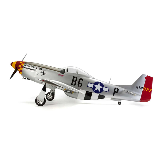
Hangar 9 P-51D Mustang 60cc Instruction Manual
Almost-ready-to-fly
Hide thumbs
Also See for P-51D Mustang 60cc:
- Instruction manual (113 pages) ,
- Assembly manual (56 pages) ,
- Instruction manual (60 pages)

Related Manuals for Hangar 9 P-51D Mustang 60cc


Summary of Contents for Hangar 9 P-51D Mustang 60cc
- Page 1 P-51D Mustang 60cc Instruction Manual Bedienungsanleitung Manuel d’utilisation Manuale di Istruzioni...
-
Page 2: Safety Warnings And Precautions
Read and follow all instructions and safety precautions airworthy. before use. Improper use can result in fi re, serious injury and Horizon Hobby, LLC. For up-to-date product literature, visit horizonhobby. com and click on the support tab for damage to property. this product. -
Page 3: Warnungen Und Sicherheit- Svorkehrungen
Überwachung eines Erwachsenen. Verwenden Sie das Produkt nicht mit inkompatiblen Komponenten oder Gebrauch oder Entsorgung von Akkus. Falsche Behandlung verändern es in jedweder Art ausserhalb der von Horizon Hobby, LLC vorgegebenen Anweisungen. Diese von LiPo Akkus kann zu Feuer mit Körperverletzungen und Bedienungsanleitung enthält Anweisungen für Sicherheit, Betrieb und Wartung. -
Page 4: Avertissements Relatifs À La Sécurité
L’UTILISATION La totalité des instructions, garanties et autres documents est sujette à modifi cation à la seule discrétion d’Horizon Hobby, LLC. Pour obtenir la documentation à jour, rendez-vous sur le site horizonhobby.com et cliquez • Inspectez votre modèle avant chaque vol. -
Page 5: Avvertimenti E Precauzioni Per La Sicurezza
Non usare componenti non compatibili o alterare il prodotto in nessuna maniera al di fuori delle istruzioni fornite da Horizon Hobby, LLC. Questo kit comprende delle parti di piccole dimensioni e non Questo manuale contiene le istruzioni per un funzionamento e una manutenzione sicuri. - Page 6 SPECIFICATIONS•SPEZIFIKATIONEN• LARGE PARTS LAYOUT•BAUTEILE (OHNE KLEINTEILE)• SPÉCIFICATIONS•SPECIFICHE GRANDES PIÈCES•SCHEMA DEI COMPONENTI GRANDI 89.0 in (226 cm) 1420 sq in (91.6 dm2) Total/Totale 77.5 in (197 cm) 25.0–27.0 lb (11.3–12.2 kg) 1, 12 2-Stroke Gas/2-Takt Benziner/ 2 temps Essence/2-Tempi Gas 60cc 8-channel (or greater) with 10 servos 8-Kanal (oder mehr) mit 10 servos 8 voies (ou plus) avec 10 servos...
-
Page 7: Replacement Parts•Ersatzteile•Pièces De Rechange• Pezzi Di Ricambio
REPLACEMENT PARTS•ERSATZTEILE•PIÈCES DE RECHANGE• PEZZI DI RICAMBIO English Deutsch Français Italiano HAN477001 Fuselage Rumpf Fuselage Fusoliera HAN477002 Right Wing with Aileron and Flap Tragfl äche Rechts mit Querruder und Klappe Aile droite avec aileron et volet Semiala destra con alettone e fl ap HAN477003 Left Wing with Aileron and Flap Tragfl... - Page 8 REQUIRED RADIO EQUIPMENT (NOT INCLUDED)•ERFORDERLICHE RC AUSRÜSTUNG (NICHT IM LIEFERUMFANG)• EQUIPEMENT RADIO REQUIS (NON FOURNIS)•APPARECCHIATURE RADIO (NON COMPRESO) English Deutsch Français Italiano SPMAR9110 AR9110 9-Channel DSMX ® PowerSafe ™ Receiver AR9110 9-Kanal DSMX PowerSafe-Empfänger Récepteur DSMX PowerSafe 9 voies AR9110 Ricevitore AR9110 DSMX PowerSafe a 9 canali SPMB2200LFRX (2) 2200mAh 2S 6.6V LiFe Rx Battery...
- Page 9 REQUIRED ELECTRIC RETRACTS (NOT INCLUDED)•ELEKTRISCHES EINZIEHFAHRWERK (NICHT IM LIEFERUMFANG)• TRAIN RENTRANT ÉLECTRIQUE REQUIS (NON FOURNI)•CARRELLI RETRATTILI ELETTRICI NECESSARI (NON INCLUSI) HAN477018 (2) inch P-51D Mustang Wheel Hangar 9 P-51D Mustang 60cc: Hauptfahrwerksreifen Roues 5 ˝ pour P-51D Ruota 130mm P-51D Mustang...
- Page 10 OPTIONAL PAYLOAD RELEASE (NOT INCLUDED)•OPTIONALES NUTZLASTABWURFSYSTEM (NICHT IM LIEFERUMFANG)• DISPOSITIF DE LARGAGE OPTIONNEL (NON FOURNIS)•SGANCIO CARICHI OPZIONALE (NON COMPRESO) English Deutsch Français Italiano EFLA405 (2) Servoless Payload Release E-fl ite Servoloses Nutzlastabwurfsystem Dispositif de largage sans servo Sgancio carichi senza servo SPMA3001 Heavy-Duty Servo Extension 6 inch Servokabelverlängerung 150 mm...
- Page 11 OPTIONAL ITEMS (NOT INCLUDED)•OPTIONALE TEILE (NICHT IM LIEFERUMFANG)•ELÉMENTS OPTIONNELS (NON FOURNIS)•ARTICOLI OPZIONALI (NON COMPRESO) English Deutsch Français Italiano SPM9548 TM1000 DSMX Full Range Aircraft Telemetry Module Spektrum DSM Telemetriemodul TM1000 Module de télémétrie TM1000 DSMX Modulo di telemetria per aereo a piena portata EVOA100 Optical Kill Switch optischer Killschalter...
- Page 12 REQUIRED TOOLS (NOT INCLUDED)•BENÖTIGTES WERKZEUG (NICHT IM LIEFERUMFANG)•OUTILS REQUIS (NON FOURNIS)•ATTREZZI NECESSARI (NON COMPRESO) English Deutsch Français Italiano Black marker Faserstift Schwarz Marqueur noir Pennarello nero Clear tape klares Klebeband Ruban adhésif transparent Nastro trasparente Covering iron Folienbügeleisen Fer à entoiler Ferro da stiro per fi...
- Page 13 English Deutsch Français Italiano Pencil Stift Crayon à papier Matita Phillips screwdriver: #0, #1, #2 Phillips Schraubendreher: #0, #1,#2 Tournevis cruciforme: #0, #1, #2 Cacciavite a croce: #0, #1, #2 Pin vise Handbohrer Porte forets Trapano manuale Pliers Zange Pince Pinze Propeller reamer Propellerfeile...
-
Page 14: Before Starting Assembly
BEFORE STARTING ASSEMBLY VOR DEM ZUSAMMENBAU AVANT DE COMMENCER L’ASSEMBLAGE PRIMA DI INIZIARE IL MONTAGGIO • Remove parts from bag. • Entnehmen Sie zur Überprüfung jedes Teil der Verpackung. • Retirez toutes les pièces des sachets pour les inspecter. • Togliere tutti i pezzi dalla scatola. •... - Page 15 ASSEMBLY SYMBOL GUIDE•MONTAGE SYMBOLE•GUIDE DES SYMBOLES POUR ASSEMBLAGE•GUIDA AI SIMBOLI DI ASSEMBLAGGIO Apply threadlock Ensure free rotation Use medium CA Apply oil Schraubensicherungslack verwenden Rotation sicherstellen Mittelfl üssigen Öl verwenden Sekundenkleber verwenden Utilisez du frein fi let Permettez une rotation libre Appliquez lubricant Utilisez de la colle Applicare fuido threadlock...
- Page 16 CANOPY FRAME INSTALLATION•MONTAGE DES KABINENHAUBENRAHMEN•INSTALLATION DU BÂTI DE LA VERRIÈRE•INSTALLAZIONE TELAIO CAPOTTINA Fit the forward tabs of the canopy frame into position. Again, lightly sand the tabs to remove any paint from the tabs, or lightly sand the tracks so the canopy can slide smoothly in the tracks. The canopy moves downward as it slides back so if you slightly angle the slot it will slide easier.
- Page 17 Remove the sliding frame from the fuselage. Sand the edge of the plywood frame where it will make contact with the canopy. Set the frame aside in a safe location. Nehmen Sie den Rahmen vom Rumpf ab. Schleifen Sie die Kanten an denen der Rahmen mit dem Rumpf in Berührung kommt etwas an.
- Page 18 COCKPIT SIDE AND REAR PANEL INSTALLATION•EINBAU DER SEITLICHEN UND HINTEREN COCKPITSCHIENEN•INSTALLATION DES PANNEAUX LATÉRAUX ET DU PANNEAU ARRIÈRE DU COCKPIT•INSTALLAZIONE DEL PANNELLO LATERALE E POSTERIORE DELL’ABITACOLO Install the magnets after sanding the one face of the magnet. Be sure to maintain the correct orientation of the magnets by stacking the magnets and inserting them one at a time.
- Page 19 Test fi t the rear upper side panels into the cockpit. Trim the panels as necessary to fi t into the cockpit. Glue the panels into the cockpit. Setzen Sie die oberen Seitenpanele testweise in das Cockpit ein. Passen Sie die Panele an und kleben diese ein. Positionnez les panneaux latéraux supérieurs.
- Page 20 Fit and trim the front top fi ller pieces and then glue in place using rubberized CA. Sand all mating surfaces fi rst. Passen Sie die oberen Füllstücke an und kleben diese auch mit dickfl üssigen Sekundenkleber ein. Bitte denken Sie daran alle Klebefl...
- Page 21 INSTRUMENT PANEL AND HOOD INSTALLATION•EINBAU DES INSTRUMENTENPANELS•INSTALLATION DU TABLEAU DE BORD•INSTALLAZIONE PANNELLO STRUMENTI E COFANO Install the instrument decal onto the balsa former, aligning Cut back the outer edges of the decal exposing the area Lightly sand the back of the instrument panel. This will the bottom edge of the decal with the former.
- Page 22 Sand the paint from the back of the plastic instrument panel Sand the top edge of the instrument panel at an angle to former. allow the cockpit hood to make contact with the front edge of the instrument panel and not leave a gap. Apply rubberized CA to the instrument panel edges and, with Use a scrap piece of balsa and sand it at an angle.
- Page 23 Trim the width of the instrument panel as needed to allow the panel to fi t into the cockpit 3mm forward from the raised edge of the cockpit sides. Schneiden Sie die Breite des Instrumentenpanels wie benötigt, damit es 3mm vor der nach oben laufenden Seitenkante in das Cockpit passt.
- Page 24 WINDSCREEN INSTALLATION•MONTAGE DER FRONTSCHEIBE• INSTALLATION DU PARE-BRISE•INSTALLAZIONE DEL PARABREZZA Carefully fi t and trim the instrument panel hood so it rests in the recess on the sides of the fuselage. The hood will key to the instrument panel during the fi tting, and the instrument panel will set back roughly 5/52 inch (4mm) inside the instrument panel hood.
- Page 25 Remove the pin and sand the last 3mm end of the pin where it will be glued into the sliding canopy framing. Remove any paint from inside the canopy frame pin hole. Use rubberized CA to glue the pin in place to only the sliding canopy frame. Make sure the pin is aligned squarely to the formers.
- Page 26 Notch the windscreen corners. Leave a small radius at the corner to prevent the canopy from cracking. Schneiden Sie die Ecken für die Windschutzscheibe zurecht. Lassen Sie an der Ecke einen kleinen Radius frei der verhindern soll dass die Haube bricht. Effectuez une encoche de chaque côté...
- Page 27 MAIN CANOPY INSTALLATION•MONTAGE DER KABINENHAUBE• INSTALLATION DE LA VERRIÈRE•INSTALLAZIONE DELLA CAPOTTINA PRINCIPALE With the canopy frame closed, apply 1-inch (25mm) low tack Place the canopy onto the sliding frame. With the canopy tape with the top edge of the tape 1/16-inch (1.5mm) below aligned, temporarily tape the canopy in place.
- Page 28 Remove the canopy from the fuselage. Remove the tape from one side of the canopy at a time and place the tape sticky-side up on a fl at surface and tape the ends down. Apply a second piece of tape sticky side to sticky side onto the fi rst piece of tape. Draw a line around the base of the canopy frame and place a couple of small tape squares at the bottom edge of the canopy.
- Page 29 Lift the tape from the fl at surface and using the two alignment marks and the line place the tape inside the canopy and secure in place temporarily with some small pieces of tape. Measure from the end of the canopy 1213/16 inch (325mm) and place a mark. Use a pencil to mark down the edge of the tape Nehmen Sie das Tape von der Oberfl...
- Page 30 Sand the paint away from between the tape and remove the tape. Position the canopy. Use canopy glue to secure the canopy to the canopy frame. Use low-tack tape to hold the canopy in After the glue has dried, remove the tape and the canopy and Schleifen Sie die Farbe zwischen dem Tape weg und position until the glue fully cures.
- Page 31 Use a razor saw to remove the cross bracing from the main canopy. Trennen Sie Streben vom Spant. Utilisez une lame de rasoir pour couper les renforts temporaires du couple. Usare un taglierino per togliere i supporti incrociati dalla capottina principale. The area where the braces are removed can Glue the canopy support into the canopy, positioning it 5 inches (146mm) from the front of the canopy to the front edge of the canopy support.
- Page 32 FINAL COCKPIT DETAIL INSTALLATION•ABSCHLUSS DER COCKPITDETAILIERUNG• INSTALLATION DES ÉLÉMENTS FINAUX DU COCKPIT• DETTAGLI PER L’INSTALLAZIONE FINALE DELLA CAPOTTINA M2 x 10 Use a drill and 1/16-inch (1.5mm) drill bit to drill a hole 3/8 inch (10mm) forward of the end on the rear canopy slot. Thread the screw into the hole using a #1 Phillips screwdriver.
- Page 33 Place low-tack tape in the fuselage to prevent accidentally sanding any areas that don’t need sanded. The pain needs to be scuffed to allow the brace to be glued to the fuel cell Sand the back side of the short “L” angle cut previously and Trim and fi...
- Page 34 Sand the fuel cell so the glue can adhere properly. Also sand the sides of the cockpit where the braces will contact. Sand the edge of the braces that will be glued to the fuel Check the fi t of the battery assembly into the cockpit. Sand Lightly score the plywood armor plate so it can be positioned Schleifen Sie die Tankattrappe und die Cockpitseiten für eine tank cell and sides of the cockpit.
- Page 35 Sand both the plywood armor plate and rear cockpit panel Use rubberized CA to glue the resin cast throttle to the side Sand all areas where the pilot seat will make contact. Sand inside the cockpit where they contact each other. Use epoxy panel.
- Page 36 AILERON SERVO INSTALLATION•EINBAU DER QUERRUDERSERVOS• INSTALLATION DES SERVOS D’AILERON•INSTALLAZIONE SERVO ALETTONI AILERON Glue the control stick plate into the fuselage. Make sure to Use medium grit sandpaper to sand the area in the control slide it fully forward, and that the smaller square indented stick plate where the control stick will be mounted.
- Page 37 Use sandpaper to lightly sand the bottom of the control horn Use a pin vise and a 1/16-inch (1.5mm) drill bit to drill the where it fi ts into the control surface. Remove any dirt and holes for the servo mounting screws through the backing oils from the control horn using a paper towel and isopropyl plate of the servo mount.
- Page 38 M2.5 x 10 Thread a servo mounting screw into each of the holes in the Apply a small amount of thin CA to harden the threads made Use a round toothpick or T-pin to puncture the covering for Place the servo cover back into position, Use a drill and 1/16 aileron servo mounting holes.
- Page 39 Secure the servo to the cover using the screws provided with Center the aileron servo using the radio system. Install the Secure a 6-inch (150mm) extension to the servo lead using Tie the string located inside the wing to the end of the 6-inch the servo.
- Page 40 M2.5 x 10 M3 x 80 Use the string to pull the servo extension (and lighting extension) to the root wing panel. The leads can be fi t into the holder in Secure the servo cover to the wing using six M2.5 x 10 self- the wing root to prevent them from falling back into the wing during transport.
- Page 41 RETRACT INSTALLATION•EINBAU DES EINZIEHFAHRWERKS• INSTALLATION DU TRAIN RENTRANT•INSTALLAZIONE DEI CARRELLI RETRATTILI Connect the linkage to the servo horn and aileron control Secure the retract into the wing using the hardware provided horn. With the radio on and servo centered, adjust the with the retract.
- Page 42 Use medium CA to glue the retract gear cover mount into the Use a pencil to draw a line inside the wheel well that is 7/32 Rest the surface on the edge of the wing and carefully draw retract well. Make sure to place the mount in so the cover fi ts inch (5mm) below the surface of the wing.
- Page 43 Use clear tape to secure the two 1mm x 20mm x 20mm gear Use clear tape to secure the two smaller door tabs to the door tabs together. 1mm x 30mm x 75mm hinge plate. This will be used to position the gear door stops.
- Page 44 Use the tool made in the previous steps to set the height of Apply a small amount of petroleum jelly to the hinges to the gear door stops 3/32 inch (2mm) below the surface of prevent adhesives from entering the hinges, causing them the wing.
- Page 45 Locate the door hinge plate. Note that the plate is not square as it will fi t to the angles of the cover when it is installed. Position the hinges onto the back of the retract gear cover Legen Sie die Scharnierplatte bereit. Bitte beachten Sie making sure to not cover the screw hole.
- Page 46 Check the fi t of the hinges in the pocket made by placing the Check the fi t of the hinges in the outer landing gear door. Do Fit the gear door into position. Do not use glue on the hinges. plate in position.
- Page 47 M2.5 x 10 The gear door cover can be secured to the wing. Follow the Carefully remove the gear door, but leave the tape attached Carefully trim the gear door stops to allow the gear door to fi t With the axle and wheel fi t to the strut, mark the axle so it procedure for the aileron servo cover to drill and prepare the to the wing.
- Page 48 Install both ball ends. These will receive the gear door Fit the retract strut into the retract mechanism. You may Remove the axle and cut it at the previously made mark. Use a fl at fi le to make an area where the setscrew will linkages.
- Page 49 GEAR DOOR INSTALLATION•EINBAU DER FAHRWERKSTÜREN• INSTALLATION DES TRAPPES MOBILES DE TRAIN•INSTALLAZIONE DEL PORTELLO Check the alignment between the wheel and wing root to make sure they are parallel. If not, adjust the strut as necessary to set this alignment. Secure the ball ends to the ball end painted plastic tabs that Use rubberized CA to glue the tabs into the notches in the Prüfen Sie die Ausrichtung zwischen Rad und Flächenwurzel will be glued into the notches in the outer gear door.
- Page 50 Use sandpaper to remove the paint from the clevis tab where Prepare the hinges for the gear door by applying a small it will fi t into the gear door. Use rubberized CA to glue the amount of petroleum jelly along the hinge line. Fit the hinges clevis tab into the slot in the inner gear door.
- Page 51 Front Link• Anlenkung Front• Tringlerie avant•Rinvio Anteriore Check that both the inner and outer gear doors can close Connect the links to the gear door and strut. Rear Link• Anlenkung Rear• without interference. Once the movement of the gear doors Schließen Sie die Anlenkung an Tür und Strebe an.
- Page 52 Use the retract programmer in TEST MODE to operate the landing gear. Adjust the length of the links until the gear door closes Locate the notches for the retract door servo mount and Place the retract door servo mount in the slots and trace the fl...
- Page 53 Prepare the servo mounting holes by threading the servo mounting screw into the holes. Remove the screw and apply a few drops of thin CA in each hole to harden the surrounding wood. Install the retract door servos into the mount using the hardware provided with the servos.
- Page 54 M3 x 100 Prepare the servo arm by installing the ball end screw from the side of the servo arm next to the servo so it is 1 inch (32mm) from the center of the servo arm. Carefully remove the covering and wing sheeting so the arm can rotate into Assemble the gear door linkage using the hardware listed.
- Page 55 Disconnect the linkages between the servos and inner gear Follow the instructions included with the retracts to connect the main gear to the controller unit. Connect the 2 main retract Refer to the retract instructions to place the programmer in doors.
- Page 56 The controller base programming Hier die Grundprogrammierung for this model are as follows: des Modells.: MODEL: P-51 MODEL: P-51 GEAR G1 YES* GEAR G1 YES* DELAY VERZÖGERUNG G1 0S G1 0S G2 0S G2 0S G3 0S G3 0S Once you have confi rmed the operation of the retract and door servo turn off the controller. Open the doors manually and TRAVEL reconnect the pushrod to the door.
- Page 57 La programmation de base du Le programmazioni di base del Operate the retract cycle and check that the doors open to boitier de commande pour ce Controller sono le seguenti: approximately 85° and close properly. Adjust the pushrods modèle est la suivante: or the controller programming as needed.
- Page 58 FLAP SERVO INSTALLATION•EINBAU DER KLAPPENSERVOS•INSTALLATION DE SERVOS DE VOLETS•INSTALLAZIONE DEL SERVO DEI FLAP FLAP KLAPPEN Use epoxy to glue the fl ap control horn in position. Use the technique of using low-tack tape as outlined in the installation of the aileron control horns. Before the epoxy has cured, remove the tape and slide the fl...
- Page 59 Route all the leads through the wing center section at this time. Use two 24-inch (600mm) leads for the ailerons, and two 36- inch (920mm) extensions for the lighting. The ordinance release mechanisms will also require 24-inch (600mm) extensions installed in the wing center section if they have been installed. Once the epoxy has fully cured, place the fl...
- Page 60 M2.5 x 10 M3 x 120 Prepare the servo mounting holes by threading the servo mounting screw into each holes. Remove the screw and apply a few drops of thin CA in each hole to harden the surrounding wood. Secure the servo cover to the wing using Assemble the fl...
- Page 61 RUDDER INSTALLATION•EINBAU DES SEITENRUDERS•INSTALLATION DE LA DÉRIVE• INSTALLAZIONE DEL TIMONE A •OPTIONAL LIGHTING INSTALLATION •OPTIONALE BELEUCHTUNG •INSTALLATION DES ÉCLAIRAGES OPTIONNELS •INSTALLAZIONE DELLA LUCE OPZIONALE Elevator Horn Höhenruderhorn Guignol de profondeur Squadretta Elevatore Remove the screw and rudder hinge from the rudder. Entfernen Sie das Scharnier und die Schraube vom Ruder.
- Page 62 B •OPTIONAL LIGHTING INSTALLATION•OPTIONALE BELEUCHTUNG• C •OPTIONAL LIGHTING INSTALLATION INSTALLATION DES ÉCLAIRAGES OPTIONNELS•INSTALLAZIONE DELLA LUCE OPZIONALE •OPTIONALE BELEUCHTUNG •INSTALLATION DES ÉCLAIRAGES OPTIONNELS •INSTALLAZIONE DELLA LUCE OPZIONALE M3 x 10 Secure the rudder to the fuselage using the hinge wire. Thread the screw into position, then remove the screw. Apply Use hook and loop tape to secure the lighting controller and a few drops of thin CA in the threads made by the screw.
- Page 63 Prepare the servo mounting holes by threading the servo mounting screw into the holes. Remove the screw and apply a few Insert the cables into the tubes located inside the fuselage. Assemble the ends for the pull-pull cables to connect the drops of thin CA in each hole to harden the surrounding wood.
- Page 64 Center the rudder servo using the radio system and attach the servo arm so it is perpendicular to the servo centerline. Connect the clevises to the holes of the servo arm that are Slide the sleeve on the cable. The cable then goes through 25/32 inch (20mm) from the center of the arm.
- Page 65 ELEVATOR SERVO INSTALLATION•EINBAU DER HÖHENRUDERSERVOS• INSTALLATION DU SERVO DE PROFONDEUR•INSTALLAZIONE DEL SERVO ELEVATORE Follow the procedure as described for the cable ends and clevises earlier in this section of the manual. Prepare the right and left cables, connecting the clevises to the rudder Once set, secure the clevises to the rudder control horns control horn.
- Page 66 Elevator Horn Höhenruderhorn Guignol de profondeur Squadretta Elevatore Rudder Horn Seitenruderhorn Guignol de dérive Squadretta Timone Prepare the servo mounting holes by threading the servo mounting screw into the holes. Remove the screw and apply a few drops of thin CA in each hole to harden the surrounding wood. Insert the servo lead into the stabilizer. Rotate the servo arm so the elevator servo can be placed into the stabilizer.
- Page 67 M3 x 86 Connect the linkage to the servo horn and elevator control horn. With the radio on and servo centered, adjust the linkage to center the elevator. Tighten the nuts against the clevises once the linkage has been adjusted. Slide the Assemble the elevator linkage using the hardware listed.
- Page 68 STABILIZER INSTALLATION•MONTAGE DES HÖHENLEITWERKS•INSTALLATION DU STABILISATEUR•INSTALLAZIONE DELLO STABILIZZATORE Mark the stabilizer tube 4 inches (125mm) from the end Remove the covering to access the stabilizer tube screw of the tube using a felt-tipped pen. location that is 4 inches (120mm) from the root of the stabilizer.
- Page 69 M3 x 6 BHCS M3 x 10 BHCS M3 x 6 BHCS Carefully cut threads in the tube using a 3mm tap. Slide the stabilizer tube into the fuselage. Connect the lead from the elevator servo to the extension in the fuselage. Use Drehen Sie vorsichtig ein 3mm Gewinde ein.
- Page 70 TAIL GEAR RETRACT INSTALLATION•MONTAGE DES EINZIEHBAREN SPORNRAD•INSTALLATION DE LA ROULETTE RÉTRACTABLE•INSTALLAZIONE CARRELLO RETRATTILE DI CODA Apply a small amount of petroleum jelly to the tail gear door Tack glue the tail gear door mounts in the fuselage using 2 hinges. Lightly sand the surface of the hinges where they will to 3 drops of medium CA.
- Page 71 Use CA to glue the door opening stop in the fuselage. Wick thin CA around the perimeter of the tail gear door mounts to secure their location in the fuselage. Kleben Sie den Türstopper in den Rumpf. Verteilen Sie etwas dünnfl...
- Page 72 Route the extension (included with the tail gear) for the tail Crimp the ends of the door opening spring so it does not gear through the fuselage. become disconnected during the operation of your model. Führen Sie die Verlängerung (im Lieferumfang des Secure the tail gear retract in the fuselage using the Crimpen Sie die Enden der Türfeder so dass sich diese nicht Spornrades) durch den Rumpf.
- Page 73 Bend the ends of the door closing spring as shown. The Use the retract programmer in the TEST mode and the GEAR Once the spring has been adjusted, bend the ends of the spring measures 2 inch (70mm) as shown in the photo. G3 set to YES to check the operation of the tail wheel.
- Page 74 Fit the small threaded ends into the pushrod connectors at the rudder servo. Position the threaded ends so they are half-way inserted into the connector. Use an M3 x 3 setscrew to secure the ends. Slide a cable sleeve on the cable, then pass the cable through the threaded end and back through the sleeve.
- Page 75 RECEIVER INSTALLATION•EINBAU DES EMPFÄNGERS•INSTALLATION DU RÉCEPTEUR•INSTALLAZIONE DEL RICEVITORE Secure the charge receptacles and switch(es) to the radio switch plate. Connect 18 inch (460mm) leads to the charge receptacles. Mount the radio switch tray in the fuselage. Position the tray Route the leads from the charge receptacles along the sides Schrauben Sie die Ladebuchse und die Schalter auf die Montageplatte.
- Page 76 Secure the receiver in the fuselage. Connect any items that have been installed in the fuselage at this time, such as the elevator extensions, rudder servo and switch harness. Insert a hook and loop strap (not included) into the slots in the receiver tray. Choose slots that best fi t your receiver choice. Use CA to glue the receiver tray into the fuselage.
- Page 77 •ENGINE INSTALLATION •MOTOREINBAU •INSTALLATION DU MOTEUR •INSTALLAZIONE DEL MOTORE Secure the receiver batteries in the fuselage. Wrap the batteries in foam to prevent damage from vibration. Sichern Sie die Empfängerakkus im Rumpf. Wickeln Sie die Akkus in Schaumstoff ein um sie gegen Vibrationen zu schützen.
- Page 78 Remove the template and use a 9/32 inch (7mm) drill bit to Assemble the tank following the instructions included with your engine. It may be necessary to use hardware included with Place the fuel tank in the fuselage. Slide the tank forward enlarge the holes for the engine mounting blind nuts.
- Page 79 M6 x 70 Thread the ball end on the 2mm x 378mm throttle pushrod. Attach the ball to the carburetor arm. Snap the ball end onto Attach the fuel lines to the carburetor. Make sure to use Make sure the ball is secure on the threads. the ball.
- Page 80 M3 x 3 Secure the fuel tank in the fuselage using the recommended 20 x 430 hook and loop straps (not included). A thin piece of foam or two-sided tape between the tank and plywood will Prepare the servo mounting holes, then install the servo keep the tank from sliding inside the fuselage.
- Page 81 Check that the radio system can operate the carburetor. Route the leads along the sides of the fuselage. Make sure It may be necessary to adjust the settings at the radio to the leads will not interfere with the operation of your model. prevent binding of the servo.
- Page 82 Secure the ignition battery in the battery box. Wrap the battery in foam to prevent damage from vibration. The cover for the batteries can now be reinstalled on the fuselage. Tape the cowling into position on the fuselage. Make sure it rests in the recesses in the fuselage sides and aligns Sichern Sie den Zündakku in der Akkubox.
- Page 83 A (OPTIONAL•OPTIONNEL•OPZIONALE) Mount the ignition module. Connect the leads as necessary to properly operate your engine. Follow the instructions included with the engine to make sure it is located correctly The ignition switch can be located in alternate locations, Glue the two fuel pressurizer mounts together using CA. in relationship to other electronic components to avoid radio dependant on your modeling preferences.
- Page 84 B (OPTIONAL•OPTIONNEL•OPZIONALE) Glue the fuel pressurizer mount in the engine compartment The fuel pressurizer can be located in alternate locations, Place a piece of low-tack tape near the center of the engine where is can be accessed. Fit the pressurizer and route the dependant on your modeling preferences.
- Page 85 Position the baffl e in the cowling. The front of the baffl e Lightly sand the inside edge of the spinner to remove will fi t to the contour of the cowl. The edges will naturally the over spray where the spinner will contact the spinner conform to the sides of the cowl.
- Page 86 SCALE ACCESSORIES•SCALE ZUBEHÖR•ACCESSOIRES MAQUETTE•ACCESSORI IN SCALA Mount the backplate, spinner and propeller following the instructions for your model. Montieren Sie nach der Anleitung den Spinner, Propeller und Rückplatte. Use hobby scissors and a hobby knife to trim the fl ange from Partially trim the covering from the machine gun ports in the Use canopy glue to glue the machine guns into the wing.
- Page 87 A (OPTIONAL•OPTIONNEL•OPZIONALE) Use a piece of covering (not included) around the LED to Glue the navigation light lens to the wing tip. Allow the glue Secure a 36-inch (920mm) extension to the LED. Guide the extension through the wing. Use a small amount of rubberized CA cover the hole and fi...
- Page 88 Thread the antenna into the nylon lock nut located in the top of the fuselage. Press the balsa mount into the exhaust. This will leave an Use a paper towel and rubbing alcohol to remove any dirt or debris from inside the exhaust. Fit the balsa exhaust mount into Drehen Sie die Antenne in die Kunststoffmutter auf der indentation in the balsa.
- Page 89 Use rubberized CA to glue the exhaust stacks in the exhaust. Position the exhaust so the front edge is just touching the checkerboard at the front of the fuselage, and the lower edge Trim the covering on the fuselage 3/32 inch (2mm) inside the Check that the exhaust stacks are aligned parallel both from is 1/32 inch (1mm) above the seam between the fuselage and cowling.
- Page 90 OPTIONAL ORDNANCE RELEASE INSTALLATION•OPTIONALER AUSLÖSEMECHANISMUS•INSTALLATION DES DISPOSITIFS DE LARGAGE OPTIONNELS•INSTALLAZIONE OPZIONALE PER IL RILASCIO DEGLI ORDIGNI •Release Mechanism Extensions•Verlängerungen Auslösemechanismus •Rallonges des dispositifs de largage•Prolunghe per meccanismo di rilascio 36 inch (920mm) 9 inch (230mm) Use epoxy to glue the exhausts to the sides of the fuselage. Use low-tack tape to hold the exhaust in position until the 24 inch (600mm) 6 inch (150mm)
- Page 91 The release mechanism on the right uses the lead from the release. No extension is required. Bei dem Auslösemechanismus auf der rechten Seite wird keine Verlängerung benötigt. Le dispositif de droite ne nécessite pas de rallonge, il est connecté au dispositif de gauche. Il meccanismo di rilascio di destra usa direttamente il suo cavetto.
- Page 92 M2.5 x 8 Check the fi t of the release mount to the release. It may be Prepare the holes by threading the screws listed into the Use a hobby knife to make a hole in the wing for the release necessary to trim the mount or chamfer the holes in the holes, then removing them.
- Page 93 M3 x 45 Connect the 9 inch (230mm) extension to the release Insert the lead from the release mechanism and guide it to Secure the pylon to the bottom of the wing. Note there is a right and left pylon, and they will fi t to the wing contour. If they mechanism that will be installed on the left wing tip panel the wing root.
- Page 94 JOINING THE WING PANELS•ZUSAMMENSTECKEN DER TRAGFLÄCHEN•ASSEMBLAGE DES AILES•UNIRE I PANNELLI ALARI Remove the fl ap retaining plate from the tip panel. Slide the wing tubes into the outer tip panels. The tip panels can be separated from the center section for transport.
- Page 95 MOUNTING THE WING•MONTAGE DER TRAGFLÄCHE•INSTALLATION DE L’AILE•MONTAGGIO DELL’ALA M6 x 60 Fit the wing to the fuselage, guiding the wiring into position and connecting all the leads from the receiver and lighting controller. Secure the wing to the fuselage. Insert the bolts and washers into the intake scoop in preparation for the wing installation. Setzen Sie die Tragfl...
- Page 96 DECAL INSTALLATION• AUFKLEBEN DES DEKORBOGEN• POSE DES AUTOCOLLANTS• INSTALLAZIONE DEGLI ADESIVI• Apply the decals to your model using the photos located in this section of the manual and the box art from your model. Use a spray bottle and a drop of dish washing liquid or glass cleaner sprayed in the location of the decal to allow repositioning of the decal.
-
Page 98: Center Of Gravity
CENTER OF GRAVITY DER SCHWERPUNKT An important part of preparing the aircraft for fl ight is properly balancing the model. Ein sehr wichtiger Teil in der Flugvorbereitung ist es das Flugzeug richtig auszubalancieren. 1. Attach the wing panels to the fuselage. Make sure to connect the leads from the aileron to the appropriate leads from the 1. -
Page 99: Centre De Gravité
CENTRE DE GRAVITÉ CENTRO DI GRAVITA’ (BARICENTRO) Une des étapes importantes de la préparation d’un modèle est son équilibrage. Un punto importante per preparare l’aereo al volo è quello di fare un centraggio corretto. 1. Fixez les ailes au fuselage. Vérifi ez que les ailerons sont reliés aux prises appropriées du récepteur. Contrôlez que les câbles 1. -
Page 100: Control Throws
CONTROL THROWS RUDERAUSSCHLÄGE 1. Turn on the transmitter and receiver of your model. Check the movement of the rudder using the transmitter. When the stick 1. Schalten Sie den Sender und Empfänger ihres Modells ein. Prüfen Sie die Seitenruderaussschläge mit dem Sender. is moved to the right, the rudder should also move right. -
Page 101: Corse Dei Comandi
DÉBATTEMENTS CORSE DEI COMANDI 1. Mettez l’émetteur et le récepteur sous tension. Contrôlez les mouvements de la dérive en utilisant votre émetteur. Quand le 1. Accendere trasmettitore e ricevitore del modello. Controllare i movimenti del timone agendo sul trasmettitore. Quando manche est vers la droite, la dérive doit s’orienter vers la droite. -
Page 102: Preflight Checklist
PREFLIGHT CHECKLIST VORFLUGKONTROLLE CHECKLIST D’AVANT VOL LISTA DEI CONTROLLI PRIMA DEL VOLO • Charge the transmitter, receiver and motor battery for • Laden Sie den Sender- ,Empfänger- und Zündakku für • Chargez la batterie de votre émetteur, de réception • Caricare le batterie di trasmettitore, ricevitore e your airplane. -
Page 103: Daily Flight Checks
DAILY FLIGHT CHECKS TÄGLICHER FLUG CHECK CONTRÔLES SYSTÉMATIQUES CONTROLLI DI VOLO GIORNALIERI • Check the battery voltage of the transmitter battery. Do • Überprüfen Sie die Spannung des Senderakkus. Fliegen • Contrôlez la tension de la batterie de l’émetteur. Ne volez •... -
Page 104: Limited Warranty
An Online Service Request is available at accepts money orders and cashier’s checks, as well as Visa, service by anyone other than a Horizon Hobby authorized of use, setup or assembly, the user accepts all resulting http://www.horizonhobby.com/content/_service-center_ MasterCard, American Express, and Discover cards. -
Page 105: Garantie Und Service Informationen
Reparaturversuche, die nicht von Horizon ausgeführt wurden aus. Rücksendungen durch den Käufer direkt an Horizon oder Anleitung enthält Sicherheitshinweise und Vorschriften Exklusive Garantie ¬ Horizon Hobby LLC (Horizon) Liegt eine kostenpfl ichtige Reparatur vor, erstellen wir einen eine seiner Landesvertretung bedürfen der Schriftform. -
Page 106: Garantie Et Réparations
Questions, assistance et réparations Réparations payantes ou d’une manipulation erronés, d’accidents ou encore du Garantie exclusive - Horizon Hobby, LLC. (Horizon) garantit fonctionnement ainsi que des tentatives d’entretien ou de Votre revendeur spécialisé local et le point de vente ne En cas de réparation payante, nous établissons un devis... -
Page 107: Garanzia
Horizon non si riterrà responsabile per danni speciali, Se il prodotto deve essere ispezionato o riparato, si prega di La garanzia esclusiva - Horizon Hobby, LLC., (Horizon) diretti, indiretti o consequenziali; perdita di profi tto o di rivolgersi ad un rivenditore specializzato o direttamente ad garantisce che i prodotti acquistati (il “Prodotto”) sono... -
Page 108: Instructions For Disposal Of Weee By Users In The European Union
Horizon Hobby Limited +44 (0) 1279 641 097 Harlow, Essex, CM18 7NS, United Kingdom Horizon Technischer Service service@horizonhobby.de Christian-Junge-Straße 1 Germany Sales: Horizon Hobby GmbH +49 (0) 4121 2655 100 25337 Elmshorn, Germany infofrance@horizonhobby.com Service/Parts/Sales: 11 Rue Georges Charpak France... -
Page 109: Academy Of Model Aeronautics National Model Aircraft Safety Code
ACADEMY OF MODEL AERONAUTICS NATIONAL MODEL AIRCRAFT SAFETY CODE Effective January 1, 2014 EXCEPTIONS: 3. At all fl ying sites a safety line(s) must be established in C. FREE FLIGHT front of which all fl ying takes place. (AMA Document #706.) A. - Page 112 © 2014 Horizon Hobby, LLC. Hangar 9, DSMX, Evolution, SureFire, PowerSafe, EC3 and the Horizon Hobby logo are trademarks or registered trademarks of Horizon Hobby, LLC. The Spektrum trademark is used with permission of Bachmann Industries, Inc. All other trademarks, service marks and logos are the property of their respective owners.
Need help?
Do you have a question about the P-51D Mustang 60cc and is the answer not in the manual?
Questions and answers