Hangar 9 F4U-1D Corsair 50 ARF Assembly Manual
Hide thumbs
Also See for F4U-1D Corsair 50 ARF:
- Instruction manual (96 pages) ,
- Instruction manual (65 pages)
Table of Contents
Advertisement
Quick Links
Advertisement
Table of Contents

Related Manuals for Hangar 9 F4U-1D Corsair 50 ARF


Summary of Contents for Hangar 9 F4U-1D Corsair 50 ARF
- Page 1 F4U-1D Corsair 50 ARF Assembly Manual...
-
Page 2: Table Of Contents
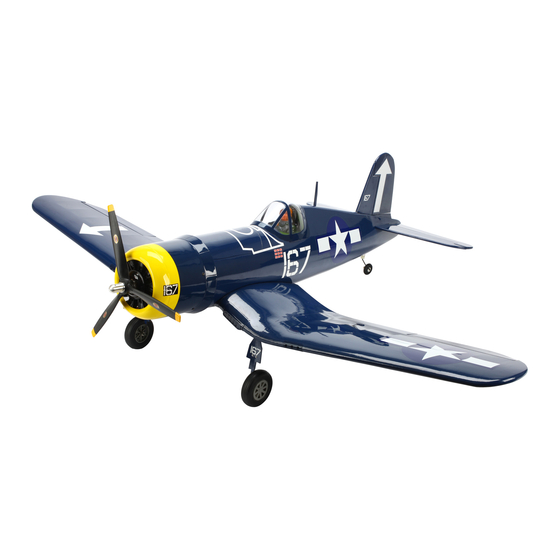
Safety Precautions and Warnings ........4 ground. Important Information Regarding Warranty ......5 The Hangar 9 F4U-1D Corsair 50 is a sport ARF tribute to Using the Manual ..............5 Meaning of Special Language this warbird legend that goes together quickly and is a joy UltraCote Covering Colors ..........5... -
Page 3: Included Parts Listing
2mm x 505mm pushrod Rudder Headrest plastic with balsa insert Fuselage 2mm x 610mm pushrod Elevator Cowl 2mm x 215mm pushrod Throttle Canopy 2mm x 53mm pushrod Aileron Dummy engine Pushrod housing 8-inch (200mm) Throttle Hangar 9 F4U-1D Corsair 50 ARF... -
Page 4: Contents Of Kit And Parts Listing
This kit includes small parts and should not be left 13. HAN259015 Pushrod Set unattended near children as choking and serious injury 14. HAN259018 EP Motor Mount Box could result. 15. HAN259021 3/4-inch Spinner Nut, 1/4-28 16. HAN242022 -inch (89mm) 8-Spoke Wheel Set Hangar 9 F4U-1D Corsair 50 ARF... -
Page 5: Important Information Regarding Warranty
EFLB40004S30 Optional Equipment E-flite Electric Retracts, 25–46 EFLG320 4400mAh 4S 14.8V G4 Pro Power 30C THP44004SP30 ® 1/9-Scale Military Pilot HAN9108 Optional: Telemetry for the DX8 SPM9548 3/4-inch spinner nut, 8mm x 1.25mm HAN259022 Hangar 9 F4U-1D Corsair 50 ARF... -
Page 6: Optional Field Equipment
Note that the shorter end fits into the outer 3/32-inch, 7/64-inch, 9/64-inch panel, while the longer end fits into the center panel. Required Adhesives 30-minute Epoxy PAAPT39 Canopy Glue PAAPT56 Silicone adhesive DEVS250 Thin CA PAAPT08 Medium CA PAAPT02 Threadlock PAAPT42 Hangar 9 F4U-1D Corsair 50 ARF... - Page 7 9. Slide the joiner into the center panel. Use an epoxy brush to apply a thin layer of epoxy to the exposed wood of the rib as shown. Apply epoxy to the center panel and to the outer wing panels at this time. Hangar 9 F4U-1D Corsair 50 ARF...
-
Page 8: Hinging The Ailerons
Prepare both the slots in the aileron and wing at this time. hint: Use low-tack tape to tape the string to the top of the wing to prevent it from falling back into the center section. Hangar 9 F4U-1D Corsair 50 ARF... - Page 9 6. Once the CA and epoxy has cured, check that all the hinges are secure by gently trying to separate the aileron from the wing panel. If any hinges are loose, re-apply CA to the loose hinges. Hangar 9 F4U-1D Corsair 50 ARF...
-
Page 10: Aileron Servo Installation
The wing assembly is also required for this section of the manual. Hangar 9 F4U-1D Corsair 50 ARF... - Page 11 20mm hardwood blocks to the servo cover. Allow the epoxy to fully cure before proceeding. Important: Do not use a CA accelerator. Using an accelerator will not allow the CA to soak into the fibers of the wood, hardening the blocks. Hangar 9 F4U-1D Corsair 50 ARF...
- Page 12 Note: Place the drill bit in the drill chuck as far 14. Use a T-pin to poke the covering in the locations as possible to help prevent accidentally drilling for the four servo cover mounting screws. through the top of the wing accidentally. Hangar 9 F4U-1D Corsair 50 ARF...
-
Page 13: Aileron Linkage Installation
21. Repeat Steps 2 though 20 to install the remaining aileron servo. Make sure you install the servo so you have a right and left servo installation. Hangar 9 F4U-1D Corsair 50 ARF... - Page 14 9. Insert the Z-bend of the 2mm x 53mm linkage in will accept the servo cover mounting screws. the hole of the servo arm that was enlarged in the previous section of this manual. Hangar 9 F4U-1D Corsair 50 ARF...
-
Page 15: Fixed Main Landing Gear Installation
Installation” if you are planning on installing the optional retracts in your model. 1. Locate the hardware to install the fixed main landing gear. The wing assembly is also required for this section of the manual. Hangar 9 F4U-1D Corsair 50 ARF... - Page 16 3. Use a hobby knife with a #11 blade to remove the covering from the mounting holes in the main landing gear. 5. Use a pencil to transfer the locations for the mounting screws onto the landing gear rails inside the wing. Hangar 9 F4U-1D Corsair 50 ARF...
- Page 17 This will make the screws more secure and help prevent them from vibrating loose. 11. Slide a 4mm wheel collar onto the landing gear wire. Do not tighten the setscrew at this time. Hangar 9 F4U-1D Corsair 50 ARF...
- Page 18 Apply a small amount of silicone adhesive between the gear door and strut wire to prevent it from rotating in flight. 19. Repeat steps 2 through 17 to install the remaining landing gear assembly and wheel. Hangar 9 F4U-1D Corsair 50 ARF...
-
Page 19: Retract Installation
Drill bit: 5/64-inch (2mm) Thin CA Canopy glue Hobby scissors Felt-tipped pen String or dental floss Hex wrench: 1.5mm (included), 2.5mm Note: If you have installed fixed gear, skip to the next section “Wing Installation.” Hangar 9 F4U-1D Corsair 50 ARF... - Page 20 7. Place a 5/64-inch (2mm) drill bit in the drill. Wrap a piece of tape around the drill bit 3/4-inch (19mm) from the end of the drill bit to prevent accidentally drilling through the top of the wing. Hangar 9 F4U-1D Corsair 50 ARF...
- Page 21 -inch (71mm) forward of the trailing can be easily accessed for the following steps. edge of the wing. Also use a ruler to make sure the template is centered in relationship to the retract strut. Hangar 9 F4U-1D Corsair 50 ARF...
- Page 22 Note: Always use threadlock on metal-to-metal fasteners to prevent them from vibrating loose. Since the collar is being used as a spacer, you will not need a flat for the setscrew on this particular wheel collar. Hangar 9 F4U-1D Corsair 50 ARF...
- Page 23 26. Snap the hub cap back into position on the wheel. Note: Always use threadlock on metal-to-metal fasteners to prevent them from vibrating loose. Hangar 9 F4U-1D Corsair 50 ARF...
- Page 24 Note: When installing the remaining retract, make sure to measure the position of the axle on the current retract to match the length of the struts exactly. Note: Always use threadlock on metal-to-metal fasteners to prevent them from vibrating loose. Hangar 9 F4U-1D Corsair 50 ARF...
-
Page 25: Wing Installation
Note: Make sure to use a new #11 blade and use light pressure to trim only the covering. Avoid cutting into the underlying wood, which could weaken the structure of your model. Hangar 9 F4U-1D Corsair 50 ARF... - Page 26 The fiberglass belly pan may not lay flat against the wing. Use a washcloth soaked in hot water to warm the fiberglass, making it pliable so you can mold it to the wing contour. Hangar 9 F4U-1D Corsair 50 ARF...
-
Page 27: Stabilizer And Elevator Installation
14. Remove the waxed paper from the fuselage to complete the belly pan installation. Leave the wing attached elevator and stabilizer. to the fuselage so the stabilizer can be installed. Hangar 9 F4U-1D Corsair 50 ARF... - Page 28 8. Double check the alignment of the stabilizer as described in steps 5 through 7. Once set, use a felt-tipped pen to trace the outline of the fuselage on the top and bottom of the stabilizer. Hangar 9 F4U-1D Corsair 50 ARF...
- Page 29 Remove any excess epoxy from the stabilizer and fuselage 12. Remove the joiner wire from the elevators. Use using denatured alcohol and a paper towel. medium grit sandpaper to roughen the 3mm metal joiner rod where it will contact the elevators. Hangar 9 F4U-1D Corsair 50 ARF...
- Page 30 19. Cut two 1 -inch (38mm) wide pieces of waxed paper. Tape the waxed paper to the stabilizer so the joiner wire doesn’t get accidentally glued to the stabilizer when the elevators are installed. Hangar 9 F4U-1D Corsair 50 ARF...
- Page 31 Set the assembly aside to cure. Important: Allow the CA to cure WITHOUT using CA accelerator. This is necessary to allow the CA to soak into the hinge, creating the best bond between the hinge and surrounding wood. Hangar 9 F4U-1D Corsair 50 ARF...
-
Page 32: Fin And Rudder Installation
4. Fit the torque rod into the rudder. The front edge of the torque rod will align with the rudder hinge line. Hangar 9 F4U-1D Corsair 50 ARF... - Page 33 10. Use low-tack tape to attach the balsa fairing to the bottom of the rudder. The trailing edge of the rudder will flow into the curve of the fairing as shown in the photo. Hangar 9 F4U-1D Corsair 50 ARF...
- Page 34 Note: Make sure to use a new #11 blade and use light pressure to trim only the covering. Avoid cutting into the underlying wood, which could weaken the structure of your model. Hangar 9 F4U-1D Corsair 50 ARF...
- Page 35 Insert the hinges into the rudder as shown. 20. Check the alignment of the fin to the stabilizer. Position the fin so it is perpendicular to the stabilizer. Use low-tack tape to keep the fin in position. Align Perpendicular Hangar 9 F4U-1D Corsair 50 ARF...
- Page 36 The gap secure by gently trying to separate the rudder from the fin. If in step 26 should match the gap in this step. any hinges are loose, re-apply CA to the loose hinges. Hangar 9 F4U-1D Corsair 50 ARF...
-
Page 37: Receiver, Receiver Battery, Servo And Linkage Installation
31. With the rudder centered, make sure the balsa fairing radio equipment. is directly under the rudder. Use a felt-tipped pen to trace the outline of the fairing onto the top of the fuselage. Hangar 9 F4U-1D Corsair 50 ARF... - Page 38 Important: Do not use a CA accelerator. Using an accelerator will not allow the CA to soak into the fibers of the wood, hardening the blocks. Hangar 9 F4U-1D Corsair 50 ARF...
- Page 39 12. Slide the hatch forward then lift it up at the rear. There are tabs near the rear edge that must clear the top of the fuselage before lifting the hatch, so make sure the hatch is slid forward as far as possible before removal. Hangar 9 F4U-1D Corsair 50 ARF...
- Page 40 Once the flat has been made, secure the adapter to the torque rod. 21. Place the tail wheel wire in the adapter with the tail Hangar 9 F4U-1D Corsair 50 ARF...
- Page 41 Make sure the tail wheel is aligned with the fuselage centerline. If not, use a flat file to change the position of the flat on the tail gear wire made in step 20. Hangar 9 F4U-1D Corsair 50 ARF...
-
Page 42: Engine And Fuel Tank Installation
1. Locate the items necessary to install the engine and fuel tank in the fuselage. The fuselage will be required for this section of the manual. Attach clevis to this hole Drawing not to scale Hangar 9 F4U-1D Corsair 50 ARF... - Page 43 #1 Phillips screwdriver. Follow the same procedure as the rudder and elevator servos to mount the throttle servo. Don’t forget to plug the throttle servo into the receiver. Hangar 9 F4U-1D Corsair 50 ARF...
- Page 44 Bend the pushrod slightly so it is parallel to the top of the servo to prevent binding. Hangar 9 F4U-1D Corsair 50 ARF...
- Page 45 #1 Phillips screwdriver to thread a 2mm x 10mm black washer head screw into the four pre-drilled holes as shown. Apply 2–3 drops of thin CA in each hole to harden the surrounding wood. Hangar 9 F4U-1D Corsair 50 ARF...
-
Page 46: Motor And Battery Installation
Note: The fuel tank has an offset fuel stopper, that when properly installed, this stopper is located towards the bottom of the fuel tank and is centered into the opening in the firewall. Hangar 9 F4U-1D Corsair 50 ARF... - Page 47 7. Use medium CA to glue the 3mm plywood battery tray support tab to the underside of the radio tray. The curve in the tab will match the lightning hole in the radio tray. Hangar 9 F4U-1D Corsair 50 ARF...
- Page 48 ESC. This will result in the motor rotating the correct direction for your model. Note: Always use threadlock on metal-to-metal fasteners to prevent them from vibrating loose. Hangar 9 F4U-1D Corsair 50 ARF...
-
Page 49: Cowling Installation
Hobby knife with #11 blade Rotary tool Sanding drum Felt-tipped pen Propeller reamer 1. Locate the items necessary to attach the cowling to the fuselage. The fuselage will also be required for this section of the manual. Hangar 9 F4U-1D Corsair 50 ARF... - Page 50 The goal is to have adequate outlets installed that secure the cowl to the fuselage. in the cowling to allow the incoming air to escape. Hangar 9 F4U-1D Corsair 50 ARF...
- Page 51 Important: Do not use a CA accelerator. Using an accelerator will not allow the CA to soak into the fibers of the wood, hardening the blocks. Hangar 9 F4U-1D Corsair 50 ARF...
-
Page 52: Pilot, Canopy And Antenna Mast Installation
An unbalanced propeller can cause vibrations to be transmitted into the airframe, which could damage the airframe or other components as well as produce unwanted flight characteristics. Hangar 9 F4U-1D Corsair 50 ARF... - Page 53 5. (Optional) Trim 1/4-inch (6mm) from the bottom of the pilot using a hobby knife with a #11 blade. Use 30-minute epoxy to secure the pilot figure in the cockpit. Hangar 9 F4U-1D Corsair 50 ARF...
-
Page 54: Radiator And Gun Installation
Also remove the ends so the radiator can fit to the wing. hint: Radius the corners to minimize catching an edge when you wipe the model down with a towel. Hangar 9 F4U-1D Corsair 50 ARF... - Page 55 Also remove the ends so the machine can fit to the wing. hint: Radius the corners to minimize catching an edge when you wipe the model down with a towel. Hangar 9 F4U-1D Corsair 50 ARF...
-
Page 56: Decal Installation
Use a paper towel as a squeegee to remove excess water from under the decal. Allow the model to rest overnight so the remaining water can evaporate. Hangar 9 F4U-1D Corsair 50 ARF... -
Page 57: Center Of Gravity
High Rate: while maintaining its great flying characteristics. 9/16-inches 14mm Down: 9/16-inches 14mm Low Rate: 5/16-inches Down: 5/16-inches Rudder: High Rate: Right: -inches 57mm Left: -inches 57mm Low Rate: Right: -inches 32mm Left: -inches 32mm Hangar 9 F4U-1D Corsair 50 ARF... -
Page 58: Preflight
If any critical switches are on without your knowledge, the transmitter alarm will sound a warning at this time. • 6. Check that all trim levers are in the proper location. • 7 . All servo pigtails and switch harness plugs should be secured in the receiver. Make sure the switch harness moves freely in both directions. Hangar 9 F4U-1D Corsair 50 ARF... -
Page 59: Warranty And Repair Policy
Horizon. Return of any Product appropriate horizon Product Support office. by Purchaser must be approved in writing by Horizon before shipment. Hangar 9 F4U-1D Corsair 50 ARF... -
Page 60: Compliance Information For The European Union
877-504-0233 Exceptions: waste equipment for recycling, please contact your local city • F ree Flight fuses or devices that burn producing smoke and are office, your household waste disposal service or where you securely attached to the model aircraft during flight. purchased the product. Hangar 9 F4U-1D Corsair 50 ARF... - Page 61 5. RC model aircraft will not operate within three (3) miles of any pre-existing flying site without a frequency-management agreement (AMA Documents #922- Testing for RF Interference; #923- Frequency Management Agreement) Hangar 9 F4U-1D Corsair 50 ARF...
-
Page 62: Building And Flying Notes
Building and Flying Notes Hangar 9 F4U-1D Corsair 50 ARF... - Page 63 Building and Flying Notes Hangar 9 F4U-1D Corsair 50 ARF...
- Page 64 © 2011 Horizon Hobby, Inc. The Spektrum trademark is used with permission horizonhobby.com of Bachmann Industries, Inc. Hangar9.com All other marks are trademarks or registered trademarks of Horizon Hobby, Inc. Printed 01/2011 28755...
Need help?
Do you have a question about the F4U-1D Corsair 50 ARF and is the answer not in the manual?
Questions and answers