Table of Contents
Advertisement
Quick Links
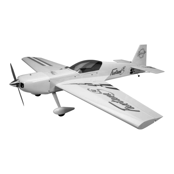
The new FuntanaS™ .90 3D ARF was designed exclusively for Hangar 9
Sebastiano Silvestri. He based the FuntanaS on his highly successful KatanaS TOC design.
The FuntanaS can do it all—harriers, torque rolls, blenders, and almost anything else you can dream up. It's all
possible, thanks to an extremely lightweight, all-wood airframe and big control surfaces that give the FuntanaS a very
impressive thrust-to-weight ratio and crisp control authority at any airspeed. Sebastiano's signature UltraCote
scheme and factory-painted parts such as the cowl and wheel pants complement the performance perfectly.
Specifications
Wingspan: .............. 69.5 in (1765.30 cm)
Length: ................... 68.5 in (1739.90 cm)
Wing Area: .............. 1107.80 sq in (71.47 sq dm)
Weight: ................... 8–8.5 lb (3.63 kg–4.03 kg)
WE GET PEOPLE FLYING
FuntanaS
ASSEMBLY MANUAL
TM
®
™
90
®
by Italy's most famous aerobatic pilot,
Radio: ..................... 4-channel w/6 servos
Engines: ................. .91–1.00 4-stroke
.61–1.00 2-stroke
®
trim
Advertisement
Table of Contents

Related Manuals for Hangar 9 FuntanaS 90


Summary of Contents for Hangar 9 FuntanaS 90
- Page 1 ™ ASSEMBLY MANUAL ® The new FuntanaS™ .90 3D ARF was designed exclusively for Hangar 9 by Italy’s most famous aerobatic pilot, Sebastiano Silvestri. He based the FuntanaS on his highly successful KatanaS TOC design. The FuntanaS can do it all—harriers, torque rolls, blenders, and almost anything else you can dream up. It’s all possible, thanks to an extremely lightweight, all-wood airframe and big control surfaces that give the FuntanaS a very ®...
-
Page 2: Table Of Contents
Table of Contents Table of Contents ............2 Covering Colors . -
Page 3: Covering Colors
Contents of Kit Large Parts: Small Parts: A. Wing Set HAN2677 1. 2 " Wheels HAN305 B. Fuselage w/Hatch HAN2676 2. Fuel Tank HAN1987 C. Tail Set HAN2678 3. Engine Mount HAN90M D. Landing Gear HAN2685 Items Not Shown: E. Canopy HAN2681 F. -
Page 4: Additional Required Equipment (Not Included)
Use the Correct Propeller! The FuntanaS 90 was designed specifically for the 3D flight envelope, which favors thrust over speed. Flying your aircraft at high speeds may cause flutter due to the extremely large control surfaces. To keep the speed down and thrust up, use low-pitch propellers such as a 16x4 APC wide for engines such as the Saito ™... -
Page 5: Warranty Information
Before Starting Assembly Before beginning the assembly of your FuntanaS 90™, remove each part from its bag for inspection. Closely inspect the fuselage, wing panels, rudder, and stabilizer for damage. If you find any damaged or missing parts, contact the place of purchase. -
Page 6: Section 1 - Aileron Servo Installation
Section 1 – Aileron Servo Installation Required Parts Step 3 • Wing panel (right and left) Tie a weight to a piece of string. A wheel collar works great in this application. Lower the string into the wing Required Tools and Adhesives from the aileron servo opening. -
Page 7: Section 2 - Installing The Ailerons
Section 2 – Installing the Ailerons Required Parts Step 3 • Wing (right and left) • Aileron (left and right) Slide the aileron and wing together. The gap between the aileron and wing should be approximately 1/64". • CA hinge (10) Required Tools and Adhesives •... - Page 8 Section 2 – Installing the Ailerons Step 5 Step 7 Remove the T-pins and apply Thin CA to each hinge. Work the aileron up and down several times to work in Make sure the hinge is fully saturated with CA. Use a the hinges and check for proper movement.
-
Page 9: Section 3 - Aileron Control Horn Installation
Section 3 – Aileron Control Horn Installation Required Parts Step 2 • Wing panel (left and right) Remove the backplate from one of the large control horns. Attach the ball end to the center hole of the • Aileron (left and right) control horn using a 4-40 x 1/2"... - Page 10 Section 3 – Aileron Control Horn Installation Step 5 Step 7 Using a 1/16" drill bit, carefully drill the holes for Attach the control horn to the aileron using three 2mm x mounting the control horn. 20mm self-tapping screws. Step 6 Step 8 Apply 2-3 drops of Thin CA into each of the three holes.
-
Page 11: Section 4 - Wing Tube Installation
Section 4 – Wing Tube Installation Required Parts Step 2 • Wing panels • Fuselage Carefully slide the remaining wing panel onto the wing tube that projects from the fuselage. The fit may be • 1/4-20 x 2" nylon bolt (2) • Wing tube tight;... -
Page 12: Section 5 - Wing Fillet Installation
Section 5 – Wing Fillet Installation Required Parts Step 3 • Fuselage • Wing tube Test fit the fillet by pulling the wing slightly away from the fuselage and aligning the two dowels in the fillet with • Wing (right and left) the corresponding holes in the wing. - Page 13 Section 5 – Wing Fillet Installation Step 4 Step 5 Once satisfied with the fit, glue the wing fillet to the wing Repeat Steps 1 through 4 for the remaining wing panel using 30-minute epoxy. Secure the wing to the fuselage and wing fillet.
-
Page 14: Section 6 - Installing The Horizontal Stabilizer
Section 6 – Installing the Horizontal Stabilizer Required Parts Step 3 • Wing • Fuselage The last alignment step is making sure the wing and stabilizer are parallel. If they are not, sand the • Horizontal stabilizer opening in the fuselage for the stab until the stab •... - Page 15 Section 6 – Installing the Horizontal Stabilizer DO NOT cut into the underlying wood. Let the knife Note: Do not omit the following steps. The “float” across the covering. Cutting into the wood will tail supports are required to assure the weaken the stabilizer and may cause it to fail in flight.
-
Page 16: Section 7 - Installing The Vertical Stabilizer
Section 7 – Installing the Vertical Stabilizer Required Parts Step 3 • Fuselage • Vertical stabilizer Remove the covering 1/16" below the line drawn in the last step. Required Tools and Adhesives • 30-minute epoxy • Sandpaper • Square • Ruler Step 1 Locate the vertical stabilizer (fin) and slide it into position. -
Page 17: Section 8 - Tail Wheel Installation
Section 8 – Tail Wheel Installation Required Parts Step 3 • Fuselage assembly • Rudder Test fit the tail wheel bracket into the rudder. Make sure there is plenty of clearance for the bracket bushing and • Tail wheel assembly the hole has been drilled deep enough to fit the tail Required Tools and Adhesives wheel wire. -
Page 18: Section 9 - Rudder Installation
Section 8 – Tail Wheel Installation Step 5 Step 6 Test fit the tail wheel bearing into the slot. Make the Apply a light coat of petroleum jelly onto the tail gear slot large enough that the bushing will fit without wire where the bearing will ride. - Page 19 Section 9 – Rudder Installation Step 3 Step 5 Test fit the rudder to the fuselage. Make sure the tail Check to make sure the rudder moves freely. It should gear wire goes into the rudder, and that the rudder will not rub against the fin at the tip.
-
Page 20: Section 10 - Elevator Installation
Section 10 – Elevator Installation Required Parts Step 4 • Fuselage assembly • CA hinge (6) Check to make sure the elevator moves freely. It should not rub against the stabilizer at the tip. Apply thin CA to • Elevator (right and left) both sides of the hinge. -
Page 21: Section 11 - Rudder And Elevator Servo Installation
Section 11 – Rudder and Elevator Servo Installation Required Parts Step 2 • Fuselage Fasten the servos in place using the screws included with the servos. Required Tools and Adhesives • Drill • Drill bit: 1/16" • Dental floss or string •... -
Page 22: Section 12 - Final Linkage Installation
Section 12 – Final Linkage Installation Required Parts Step 2 • Fuselage Plug in the elevator servo and turn on the radio system to center the servo. Place a Heavy-Duty Servo Arm Required Tools and Adhesives (JRPA215) on the elevator servo as shown. Trim the •... - Page 23 Section 12 – Final Linkage Installation Step 4 Step 6 Attach the servo arm to the servo. Remove the back Apply 2-3 drops of Thin CA into each of the three holes. plate from one of the control horns and connect the This will harden the wood and prevent the screws from clevis to the center hole.
-
Page 24: Section 13 - Landing Gear And Wheel Installation
Section 12 – Final Linkage Installation Step 8 Step 10 Adjust the elevator linkage so the elevator is centered Repeat Steps 1 through 8 using the 5” linkage when the linkage is connected to the servo. for the rudder. Step 9 Repeat Steps 1 through 8 using the 3 "... - Page 25 Section 13 – Landing Gear and Wheel Installation Step 2 Photo for Step 3 Install the landing gear using two 8-32 x 3/4" screws. Note that one edge of the gear is straight and the other at a slight angle. The straight side faces forward. Note: It may be necessary to open the notch in the wheel pant slightly to fit over the hex on the axle.
- Page 26 Section 13 – Landing Gear and Wheel Installation Step 6 Step 8 Attach the wheel to the axle using two wheel collars and Position the wheel so it is centered in the wheel pant. set screws. The exact position of the wheel will be Tighten the collars once the wheel has been positioned.
-
Page 27: Section 14 - Fuel Tank Assembly
Section 14 – Fuel Tank Assembly Required Parts Step 2 • Clunk (fuel pickup) • Metal caps (2) Locate the rubber stopper. Insert the short metal fuel tubes into one of the holes in the stopper so that an • Fuel tank •... - Page 28 Section 14 – Fuel Tank Assembly Step 5 Step 7 Slide the vent tube into one of the remaining two holes Carefully insert the stopper assembly into the fuel tank. in the stopper from the tank (small cap) side. Note the position of the vent tube; it must be up at the top portion of the fuel tank to function properly.
-
Page 29: Section 15 - Engine Installation
Section 15 – Engine Installation Required Parts Note: Check to see which direction the needle valve is pointing. It should point • Fuselage assembly • Engine mount (2) towards the top of the aircraft. Remove the • 8-32 x 1 "... -
Page 30: Section 16 - Throttle Pushrod Installation
Section 15 – Engine Installation Step 5 Photo for Step 5 Attach the engine using four 8-32 x 1-1/4" socket head screws, eight #8 washers and four 8-32 lock nuts. Section 16 – Throttle Pushrod Installation Required Parts • Clevis •... - Page 31 Section 16 – Throttle Pushrod Installation Step 2 Step 5 Test fit the throttle pushrod tube through the firewall and Install the servo hardware (grommets and eyelets) into the fuselage. Once satisfied with the fit, roughen the included with the servo. Mount the throttle servo with the tube using sandpaper.
- Page 32 Section 16 – Throttle Pushrod Installation Step 7 Step 8 Move the carburetor to the half-throttle position. Mark Remove the clevis from the pushrod. Slide the pushrod the pushrod where it crosses the throttle arm using a into the pushrod tube from the firewall. Attach the “Z” felt-tipped pen.
-
Page 33: Section 17 - Fuel Tank Installation
Section 17 – Fuel Tank Installation Required Parts Step 2 • Fuselage assembly • Fuel tank assembly Install the fuel tank into the fuselage. Make any necessary supports to keep the tank from • Fuel tubing (red and green) moving during flight. Required Tools and Adhesives •... -
Page 34: Section 18 - Electric Motor Installation
Section 18 – Electric Motor Installation Required Parts Step 3 • Fuselage Install the motor mount of your choice. The Aero-Model mount is a perfect fit and uses the original engine Required Tools and Adhesives mounting locations. • Electric motor (Hacker recommended) •... - Page 35 Section 18 – Electric Motor Installation Step 5 Step 7 Use connectors or solder to make the connection Construct a mount inside the fuselage for the battery. between the electronic speed control and motor. Mount The mount should be sturdy enough to keep the the speed controller to the side or bottom of the motor battery packs secure during the most extreme flight mounting box to provide adequate cooling.
-
Page 36: Section 19 - Cowling Installation
Section 19 – Cowling Installation Required Parts Step 3 • Fuselage assembly • Cowling Remove the cowl and remove the necessary material to fit the cowl over the engine. Install the engine back onto • #4 washer (4) the firewall, and test fit the cowl over the engine. •... -
Page 37: Section 20 - Final Radio Installation
Step 5 Step 7 Use the cardstock from Step 1 to locate the positions Attach the cowl using four 4-40 x 1/2" socket head for the cowling screws. Drill the locations using a screws and four #4 washers. 1/8" drill bit. Step 6 Make any cutouts in the cowling to clear items such as the muffler, fueling valve, needle valve, etc. - Page 38 Section 20 – Final Radio Installation Step 2 Step 3 Use plywood to build a tray for the receiver and battery. Route the antenna out through the tube in the fuselage. Temporarily mount the receiver near the aft edge of the Step 4 hatch, and the battery near the fuel tank.
-
Page 39: Section 21 - Hatch Assembly
Section 21 – Hatch Assembly Required Parts Step 4 • Hatch • Canopy Lightly sand the inside edge of the canopy and slightly inside the line drawn on the hatch using • 4-40 x 1/2" screw (4) • #4 washer (4) medium sandpaper. -
Page 40: Preflight
Preflight For those of you who are veterans of large models, this Maintain the proper mechanical advantage is old news. But to you newcomers to the world of large on all control surface linkages. models, this is very important information. As with unsealed hinge gaps, this is often the cause of While many smaller models are very tolerant of improper flutter. -
Page 41: Radio Setup
Radio Setup With a 6-channel computer radio, it will be necessary A 7-channel or greater computer radio is highly recommended. This allows the following features: to Y-harness the two elevator servos; a reversed elevator servo is needed to achieve the correct control •... -
Page 42: 2004 Official Ama National Model Aircraft Safety Code
2004 Official AMA National Model Aircraft Safety Code 7) I will not operate models with pyrotechnics (any GENERAL device that explodes, burns, or propels a projectile of 1) I will not fly my model aircraft in sanctioned any kind) including, but not limited to, rockets, events, air shows or model flying demonstrations explosive bombs dropped from models, smoke until it has been proven to be airworthy by having... - Page 43 2004 Official AMA National Model Aircraft Safety Code equipment on Amateur Band frequencies.) Organized RC Racing Event 5) Flying sites separated by three miles or more are 10) An RC racing event, whether or not an AMA Rule considered safe from site-to site interference, even Book event, is one in which model aircraft compete when both sites use the same frequencies.
- Page 44 ® WE GET PEOPLE FLYING © 2004 Horizon Hobby, Inc. 4105 Fieldstone Road Champaign, Illinois 61822 (877) 504-0233 www.horizonhobby.com 6370...
Need help?
Do you have a question about the FuntanaS 90 and is the answer not in the manual?
Questions and answers