Table of Contents
Advertisement
Quick Links
Advertisement
Table of Contents

Related Manuals for Bodyguard T-30


Summary of Contents for Bodyguard T-30
- Page 1 #691059 rev A 12/15...
-
Page 3: Table Of Contents
3.3 CONSOLE (T-30) ....................... 16 3.4 CONSOLE (T-45 & T-75) ....................16 3.5 MAIN KEYPAD (T-30 & T-45) ..................... 18 3.6 MAIN KEYPAD (T-75) ......................18 3.7 CONSOLE FEATURES ...................... 19 ... - Page 4 TREADMILLS – USER MANUAL SETTINGS MENU ..................37 5.1 ACCESSING THE SETTINGS MENU ................37 5.2 LANGUAGE ........................38 5.3 WEIGHT UNIT ........................38 5.4 DISTANCE UNIT ........................ 38 5.5 USER IDENTIFICATION ....................38 ...
- Page 5 TREADMILLS – USER MANUAL 7.2 DRIVE BELT TENSION CHECK ..................51 7.3 DRIVE BELT ALIGNMENT ....................51 7.4 WALKING BELT TENSION CHECK ................... 52 7.5 WALKING BELT ALIGNMENT ................... 52 7.6 DECK & WALKING BELT CONDITION CHECK ..............54 ...
-
Page 6: Introduction
Dealer Store Name Dealer Phone Number PRODUCT WARRANTY It is important that you register your purchase with Bodyguard Fitness within 30 days of the purchase date so your product’s warranty is activated. Product warranties are not transferrable so to avoid delays... -
Page 7: Important Safety Instructions
Any changes or modifications to this equipment could void the product warranty. Refer servicing to qualified Bodyguard Service personnel only. If you have any questions about the assembly, proper use or repair of your treadmill, please contact Bodyguard Fitness Customer Service. An Authorized... - Page 8 • power, unplug the power cord from the outlet and carefully retrieve it. If the item cannot be reached contact Bodyguard Fitness customer support. Do not operate where aerosol (spray) products are being used or where oxygen is being •...
- Page 9 TREADMILLS – USER MANUAL Do not place liquids of any type on or near the unit, except in a bottle holder or accessory • tray. Securely lidded containers are recommended. Do not exceed the maximum user weight as outlined in the product specifications. •...
-
Page 10: Grounding Instructions
TREADMILLS – USER MANUAL GROUNDING INSTRUCTIONS This product must be correctly grounded. If it should malfunction or break down, grounding provides a path of least resistance for electric current to reduce the risk of electric shock. This product is equipped with a cord having an equipment-grounding conductor and a grounding plug. The plug must be plugged into an appropriate outlet that is properly installed and grounded in accordance with all local codes and ordinances. -
Page 11: Radio Frequency Interference (Rfi)
Consult an experienced radio/TV technician for help. • WARNING - Per FCC rules, changes or modifications not expressly approved by Bodyguard could void the user’s authority to operate the equipment. Canadian Department of Communications... -
Page 12: Static Electricity
TREADMILLS – USER MANUAL STATIC ELECTRICITY Treadmills are powerful machines that can generate static electricity, causing some users to receive a shock. In excess amounts, static electricity can damage the treadmill's electronic components. There are simple steps you can take to reduce the risk of being shocked by your treadmill. If you are unable to troubleshoot the problem successfully, have the machine professionally serviced. -
Page 13: Using The Emergency Stop System
TREADMILLS – USER MANUAL USING THE EMERGENCY STOP SYSTEM This treadmill is equipped with an emergency stop system comprising of a clip tied to a safety key that slots into a safety switch inside the console. When the clip is pulled the safety key is removed from the its slot in the console, opening the safety switch which will stop the walking belt and place the console into a pause mode for the countdown duration displayed on the screen. -
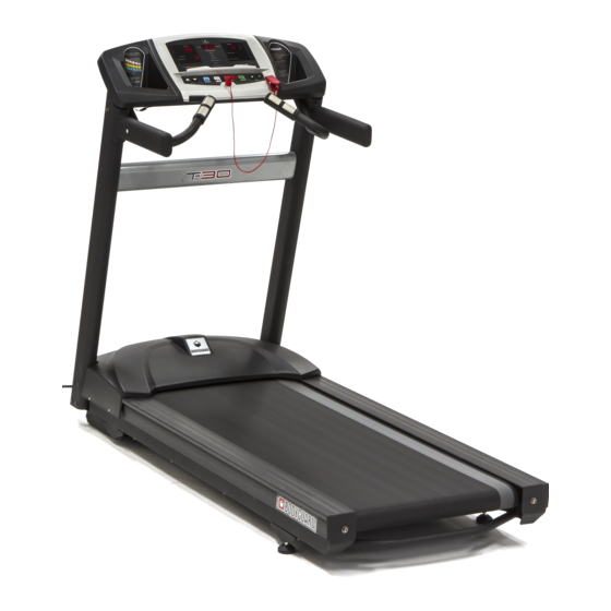
Page 14: Getting To Know Your Treadmill
TREADMILLS – USER MANUAL GETTING TO KNOW YOUR TREADMILL MAIN FRAME COMPONENTS T-30 model shown... -
Page 15: Console Overview
TREADMILLS – USER MANUAL CONSOLE OVERVIEW The table below compares the main features of the different consoles. T-30 T-45 T-75 Display Type 5 Window Red L.E.D. Blue L.C.D. Blue LCD & White L.E.D. Parameters Displayed 0.5 - 12mph 0.5 - 12mph 0.5 - 12mph... -
Page 16: Console (T-30)
TREADMILLS – USER MANUAL CONSOLE (T-30) The T-30 console features 5 Red L.E.D. Data Windows that show the parameters of the exercise under way as well as a clear program list and a convenient reading rack/device holder. T-30 Console CONSOLE (T-45 & T-75) The T-45 and T-75 consoles feature a 6.5”... - Page 17 TREADMILLS – USER MANUAL T-45 Console T-75 Console...
-
Page 18: Main Keypad (T-30 & T-45)
TREADMILLS – USER MANUAL MAIN KEYPAD (T-30 & T-45) The T-30 & T-45 MAIN KEYPAD has 8 silicone keys. From left to right these keys are: INCREASE INCLINE (BLUETOOTH ON/OFF) DECREASE INCLINE, iTEK (HOME), COOL DOWN, STOP (PAUSE), JUSTGO (ENTER), INCREASE SPEED and DECREASE SPEED. -
Page 19: Console Features
INCREASE INCLINE key a second time before the 30 seconds has passed will turn the Bluetooth Connecting feature off. COOL DOWN KEY (T-30 & T-45 only) Press this key to begin a cool-down period on compatible programs. (see section 5.9) INCREASE/DECREASE INCLINE KEYS Pressing these keys allows you to modify the angle of the walking belt during the exercise. - Page 20 TREADMILLS – USER MANUAL JUSTGO (ENTER) KEY This key has different functions depending on the unit and operational stage of the equipment. On all models, when at the HOME SCREEN; Press the green JUSTGO key to start a JustGo workout without inputting any parameters. On all models, when the 3, 2, 1 workout countdown is in action: Press the JUSTGO key to skip the countdown and begin the program.
- Page 21 TREADMILLS – USER MANUAL QUICK SPEED KEYS (T-45 & T-75 only) These keys allow you to quickly modify the speed of the walking belt during an exercise without having to use the INCREASE/DECREASE SPEED keys. Once a quick speed button has been pressed the ENTER key must be pressed to confirm the selection.
-
Page 22: Workout Parameters
Some parameters are permanent and some toggle in the same location. On a T-45 & T-75 display, extra parameters scroll across the alphanumeric screen during a workout and some parameters, such as workout totals or averages are displayed there at the end of the workout. T-30 T-45 T-75 Average Speed* ✔... -
Page 23: Parameters Glossary
ELAPSED TIME: Indicates the amount of time accumulated from the start of any program. On a T-30, the time will range from 0 to a maximum of 6 hours during the JustGo program and from 0 to 99 minutes during all other time-based programs. -
Page 24: Measuring Your Heart Rate
For safety reasons, the contact heart rate is disabled above 4mph (6.4 km/h). On a T-30 if a user grasps the contact heart rate at or above 4mph (6.4 km/h) then the heart rate data window will remain empty and no contact heart rate info will be shown. -
Page 25: Maximum Heart Rate (Mhr)
This will help you select the correct type of exercise program or level for your exercise. WARNING: It is recommended that you never exceed 90% of your Maximum Heart Rate while exercising on a Bodyguard Fitness product. On the Programs List, you will find several Heart Rate Training Programs whose Heart Rate parameters are based on the above chart. -
Page 26: Exercise Programs
40-minute exercise program will consist of 20 two-minute segments. Each segment is represented on the T-45 & T-75 consoles as one flashing block in the profile. The T-30 does not have a profile on the console; however, most programs are still broken into 20 equal segments. -
Page 27: Program Setup
When at the HOME SCREEN press the SPEED UP/DOWN keys to scroll through the entire program list. On the T-30 a small red L.E.D. will light beside the current program name. On the T-45 & T-75 the program names will appear in the alphanumeric screen. -
Page 28: Justgo Program
The Manual Program allows the user to select a predetermined amount of time they wish to workout for from 5 minutes to 99 minutes on a T-30 or from 5 minutes to 6 hours on a T-45 & T-75. On a T-30 the user can also select a predetermined distance from 1 km / miles to 99 km / miles. -
Page 29: Random Program
Each mode affects how the computer creates the Random program. RANDOM MODES On a T-30 the Random Mode is inputted after the Weight, Time and Level have been inputted. On a T-45 & T-75 the Random Mode is the first parameter to be selected immediately after the Random program has been chosen. -
Page 30: Speed Run Program
Maximum Heart Rate value. Then a Target Heart Rate must be set by first establishing a zone to work out in. On a T-30, each Heart Rate Zone is indicated by displaying the zone’s default percentage in the Bottom Right L.E.D. Window. -
Page 31: Heart Rate Interval Program
If the heart rate receiver does not detect a signal for one (1) minute, the program will stop. On a T-30 if no Heart Rate Signal is received then the program will continue at the current speed and incline settings. -
Page 32: Fitness Test
TREADMILLS – USER MANUAL HR MODE FUNCTION Speed changes only, incline stays constant. SPEED Ideal for runners who do not want incline changes Incline changes only, speed stays constant. INCLINE Ideal for walkers who do not want to jog or run. Both Speed and Incline can change. -
Page 33: Cardiovascular Program
TREADMILLS – USER MANUAL 4:30 50.00 10.3 9:45 73.80 4:45 51.40 10.4 10:00 74.90 5:00 52.80 11.1 10:15 76.30 5:15 53.90 11.2 10:30 77.70 5:30 54.90 11.3 10:45 79.10 5:45 56.00 11.4 11:00 80.00 6:00 57.00 At the end of the test, the stage the user reached corresponds to a VO Max. -
Page 34: Runner's Intervals Program
TREADMILLS – USER MANUAL 4.18 RUNNER’S INTERVALS PROGRAM The Runner’s Interval Program has been designed for people who wish to simulate medium acceleration interval workouts. This type of training is excellent for improving average running pace and is a great calorie burner, however, it is recommended that users have a solid base fitness level before incorporating this program into their workout. -
Page 35: Custom Programs
3 speed changes within a 1-minute segment, only the value at the end of the segment is stored. Your Bodyguard treadmill offers a unique option to save the completed speed and incline values from a Heart Rate Control program which allows the user to repeat the same workout at a later date without the use of a chest strap. - Page 36 TREADMILLS – USER MANUAL Note that Memory Programs cannot be deleted, just overwritten once all 8 positions are filled. TIP: If all 8 Memory positions are saved with great profiles that you do not want overwritten simply turn the Memory option in the Settings Menu to OFF and the option to save a completed program will not appear when a workout is finished so the programs cannot be overwritten.
-
Page 37: Settings Menu
SETTINGS Menu. The following table shows the section that applies to each feature. For the T-30 the text in the brackets, e.g. S1, is what appears in the L.E.D. window to identify that setting. -
Page 38: Language
Choose your Weight unit to be calculated in pounds or kilograms. To view the current selection on a T-30, enter the SETTINGS menu and ensure S1 is displayed in the bottom left L.E.D. window. The current setting will be displayed in the bottom right L.E.D. window. -
Page 39: Stats
(JustGo excluded). On the T-30 & T-45, users can also immediately start a cool down period at any time by pressing the designated COOL DOWN key. Note that the cool down option is not available for the JustGo program, which requires the user to establish their cool down period manually. -
Page 40: Speed Limits
NOTE – The highest minimum speed setting available is 1.9 (km/h or mph) and the lowest maximum speed selection available is 2.0 (km/h or mph) On a T-30, only the maximum speed can be modified. When S3 is displayed in the bottom left L.E.D. then the current maximum speed will appear in the top right L.E.D.. -
Page 41: Memory Option
The period of time before the AUTO POWER OFF feature turns off the display may be modified from 0 to 30 minutes on a T-45 or T-75 and from 0 to 15 minutes on a T-30. Note: Selecting 0 means the display will stay ON permanently. -
Page 42: Default User Weight
5.20 DEFAULT USER WEIGHT The Default User Weight allows users of a T-30 to modify the default user weight value that appears during program setup. The factory default value that appears is 150lbs (68kg) and a user must then adjust the weight before each program to their actual weight if they would like a more accurate caloric expenditure reading. -
Page 43: Diagnostics Menu
• At the HOME SCREEN, press and hold the iTEK key for 3 seconds. On a T-30 the central window will display “dIAG”, the top left L.E.D. window will display the M.C.B. software version (e.g. “43”) and the top right L.E.D. window will display the console software version (e.g.“0.32”). -
Page 44: Nvram Test
KEYPAD TEST The KEYPAD TEST (Code “d1” on a T-30) allows you to verify if each key on the console is functioning correctly. During the test, when you press on a console key a confirmed response labeling that key should appear on the screen. -
Page 45: Heart Rate Test
Note: An INCLINE CALIBRATION must always be performed after a new Motor Control Board is installed or if the INCLINE MOTOR becomes stuck in the wrong position. Completing an incline calibration on a T-30 is done manually, please contact your Bodyguard Service Provider or the Bodyguard Customer Service department for assistance. -
Page 46: Motor Check (Drive Motor Test)
The drive motor will start and the belt will reach a speed of 2.0 mph (or 3.2 km/h). You should see ESC ON (ON on T-30) appear on the screen. If you incline the treadmill to its... -
Page 47: Speed Sensor Test
Enter the DIAGNOSTICS Menu, scroll and select MAINTENANCE (or “d6” on a T-30) and press ENTER. On a T-30 the average current drawn by the motor in DC amperes since the last reset will display in the top left L.E.D. window (e.g. 8.4). Press the STOP key to return to the DIAGNOSTICS menu. -
Page 48: Statistics
TOTAL DISTANCE indicates the total distance traveled on the treadmill during all exercise programs. On a T-30 the distance L.E.D. will light first and a total distance value in miles or kilometers (depending on the setting) will display. Followed by a total time value (months, days, hours, mins, sec) Press the STOP key to terminate the test and return to the DIAGNOSTICS menu. - Page 49 TREADMILLS – USER MANUAL The console can be unlocked so the treadmill may be used again by following the below procedure but we strongly recommend this is only done after the maintenance has been performed. To unlock the console from an EXTREME AMPERAGE (ERROR 60) warning; 1) Press the ITEK button once then the ENTER key, to enter the DIAGNOSTICS menu.
-
Page 50: General Maintenance
TREADMILLS – USER MANUAL GENERAL MAINTENANCE Bodyguard Treadmills have been designed to provide many years of quality use. However, in order to maintain product safety, performance and to maximize the life the product, some general maintenance should be performed periodically. -
Page 51: Drive Belt Tension Check
TREADMILLS – USER MANUAL compressed air and blow out any accumulated dust from inside the motor and on the motor control board as well as any other effected components. • Check the drive belt tension to ensure it is not too loose (results in the belt slipping on the drive motor pulley and front roller pulley and creating a jerking feel) or too tight (puts strain on the drive motor shaft and results in the drive system working much harder than necessary as well as putting increased strain on the front roller bearings which can cause them to wear prematurely). -
Page 52: Walking Belt Tension Check
This will cause damage to the edge of the walking belt resulting in fraying. Bodyguard treadmills use crowned rollers that are contoured to help keep the belt centered, however, if the front and rear rollers are not parallel then the walking belt will drift... - Page 53 TREADMILLS – USER MANUAL rollers are adjusted at the time of installation and again during general maintenance to apply the correct amount of walking belt tension. It is important that when adjusting the walking belt tension via the rear rollers the two rear roller screws are adjusted equally so the rear roller remains parallel with the front roller.
-
Page 54: Deck & Walking Belt Condition Check
Extreme Amperage (Error 60) warning has been triggered. Determining the condition of your deck and walking belt is very easy on a Bodyguard Treadmill as there are built in electronic systems which allow you to get real-time performance feedback on the amperage (DC) being drawn by the drive motor as well as its average over a period of time. -
Page 55: Average Amperage
Note: If maintained periodically per the General Maintenance Timetable (see section 7.1), Bodyguard’s walking belts can usually be lubricated several times over years of use (thousands of miles/kilometers). Eventually, the walking belt becomes so worn that the lubricant is no longer effective at lowering the friction level between the walking belt and deck and AFDS Maintenance Warnings will continually appear on screen. - Page 56 (4) areas of use resulting in longer deck life before requiring replacement. 4. Once the deck and underside of the belt is clean and dry, apply official Bodyguard lubricant into the front middle part of the deck where the feet strike. Never put other sprays or liquids on the deck or add lubricant to a dirty deck or belt as this may cause gumming problems and increase friction between the two parts.
-
Page 57: Changing A Walking Belt
Replacement walking belts can be ordered from your service provider or Bodyguard Customer Service. When changing the walking belt inspect the deck surface and if there are signs of significant wear it is recommended to flip or rotate the deck at the same time (see section 7.9) -
Page 58: Rotating Or Flipping A Deck
Bodyguard’s treadmill decks are treated with phenolic on both sides and specially designed to be able to be rotated and flipped so an unused surface can be placed where the user’s feet strike. If the entire deck surface is worn, replacement decks can be ordered from your service provider or Bodyguard Customer Service. -
Page 59: Troubleshooting Problems
“!” on PROFILE “X” on PROFILE Maintenance warnings are part of Bodyguard’s built-in safety feature called AFDS (Advanced Friction Detection System). AFDS makes users aware when the treadmill’s drive system is working harder than usual by displaying a Maintenance Warning on the console. This is usually caused by too much friction between the deck and walking belt and can be usually resolved by performing Deck and Belt Cleaning and Lubrication. -
Page 60: Walking Belt Problems
TREADMILLS – USER MANUAL WALKING BELT PROBLEMS If your walking belt is not centered or feels like it is slipping or sticking when you are exercising it is a serious safety concern and needs to be rectified immediately. Note: The General Maintenance information in section 7, covers deck and walking belt maintenance including cleaning, lubrication, alignment and setting the correct belt tensions. -
Page 61: Common Noises
TREADMILLS – USER MANUAL COMMON NOISES There are different types of noises that can be heard from a treadmill depending on the workload, age and condition of the equipment. Treadmills do have a lot of moving components creating operational noise but if you feel there is a noise over and above what is considered normal then diagnosing the cause of noises can be made easier by taking a simple step-by step approach. -
Page 62: Rubbing, Scraping, Squeaking Or Popping Noises
TREADMILLS – USER MANUAL try to bend the wing back straight by applying heat to the plastic wing with a hairdryer. The heat will allow the wing angle to be manipulated easier and then stay in the preferred position when it cools. Alternatively, an edge of a wing can be clipped if necessary. -
Page 63: Loud Knocking/Rattling/Vibration Noises
TREADMILLS – USER MANUAL Speed Sensor Check that the speed sensor is correctly aligned around the optic disc and not making contact with it. The speed sensor can be realigned by loosening the speed sensor bracket screws and shifting the speed sensor laterally. - Page 64 TREADMILLS – USER MANUAL Incline Motor A failure to components inside an incline motor can create a loud knocking or grinding noise when the gears attempt to turn. If the noise is isolated to when the incline is changing check if the noise is coming from that part or the elevation arm beneath the treadmill.
-
Page 65: Motor Control Board (M.c.b.) Operational Codes
TREADMILLS – USER MANUAL MOTOR CONTROL BOARD (M.C.B.) OPERATIONAL CODES The Motor Control Board (M.C.B.) is the main electronic board found under the motor cover. It includes a red L.E.D. that displays an operational code indicating what state the M.C.B. is in. Use the following table to identify each of the operational codes and assist with problem solving if necessary. - Page 66 TREADMILLS – USER MANUAL Motor Power Circuit problem Usually accompanied by an Error Change Motor Control Board 51 or Error 52 on the Display If the Display has no power check if the Data Cable is connected correctly or damaged. If the Display has power, check if the Safety Key is installed and then try to start the treadmill.
-
Page 67: Display Error Codes
TREADMILLS – USER MANUAL DISPLAY ERROR CODES If an error in operation occurs, an error code will be displayed on the screen. A log of all operational errors that have occurred since the last reset can be viewed in the Diagnostics Menu. -
Page 68: Error 5 3
TREADMILLS – USER MANUAL Check if the Motor Brushes are touching the commutator. Are they worn? If so, clean with fine sandpaper and reinsert. Test. You may need to replace the Motor Brushes. Quick Motor Functionality Test using a 9V Battery: Remove the Drive Belt that is connected to the Drive Motor Pulley so the motor can turn easily. -
Page 69: Error 5 4
TREADMILLS – USER MANUAL 8.5.4 ERROR 54 DESCRIPTION: The Relay on the M.C.B. is signaling that it is closed when it should be open. ACTIONS: Defective Relay on the M.C.B.. An “A” on the M.C.B.’s L.E.D. confirms this. Change M.C.B. 8.5.5 ERROR 55 DESCRIPTION:... -
Page 70: Heart Rate Monitoring
When the equipment detects your heart rate a heart symbol begins to flash on the T-45 & T75 display and the letter Hr display on a T-30 and after a short period of time if the reading is consistent a value will be displayed. -
Page 71: Wireless Heart Rate System
The Wireless Heart Rate System is made up of four parts; the compatible 5kHz Wireless Chest Strap Transmitter the user attaches to their chest, Bodyguard’s Wireless Heart Rate Receiver in the treadmill, the cable that connects the Wireless Heart Rate Receiver to the Display and the Display. -
Page 72: General Troubleshooting Checklist
TREADMILLS – USER MANUAL a) Moisten electrodes with water b) Move machine away from potentials a) Electrodes not wet enough sources of interference (or turn them Erratic b) Interference from other signals off) such as radios, neon or Reading c) HR Receiver problem fluorescent lightning, dog fences etc. - Page 73 On a T-30, when Confirm Safety Key is in the correct place on the at the HOME console.
- Page 74 TREADMILLS – USER MANUAL...
- Page 75 TREADMILLS – USER MANUAL...
- Page 76 TREADMILLS – USER MANUAL...
Need help?
Do you have a question about the T-30 and is the answer not in the manual?
Questions and answers