Table of Contents
Advertisement
Quick Links
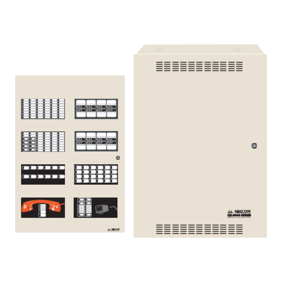
QX-5000 Series
Emergency Voice Alarm System
OPERATING INSTRTUCTIONS
1. When
these
at all
at all
QMT-5300
FIREFIGHETR'S
TELEPHONE
Installation and Operation Manual
OFF
OFF
OFF
OFF
AUTO
ON
TROUBLE
AUTO
ON
TROUBLE
AUTO
ON
TROUBLE
AUTO
ON
TROUBLE
OFF
AUTO
ON
TROUBLE
OFF
AUTO
ON
TROUBLE
OFF
AUTO
ON
TROUBLE
OFF
AUTO
ON
TROUBLE
OFF
AUTO
ON
TROUBLE
OFF
AUTO
ON
TROUBLE
OFF
AUTO
ON
TROUBLE
OFF
AUTO
ON
TROUBLE
OFF
AUTO
ON
TROUBLE
OFF
AUTO
ON
TROUBLE
OFF
AUTO
ON
TROUBLE
OFF
AUTO
ON
TROUBLE
REMOTE ANNUNCIATOR
EMERGENCY VOICE ALARM SYSTEM
LT-616 Rev. 14.1
June 2011
Advertisement
Table of Contents

Subscribe to Our Youtube Channel
Related Manuals for Mircom QX-5000 Series


Summary of Contents for Mircom QX-5000 Series
- Page 1 QX-5000 Series Emergency Voice Alarm System AUTO TROUBLE AUTO TROUBLE AUTO TROUBLE AUTO TROUBLE AUTO TROUBLE AUTO TROUBLE AUTO TROUBLE AUTO TROUBLE AUTO TROUBLE AUTO TROUBLE AUTO TROUBLE AUTO TROUBLE AUTO TROUBLE AUTO TROUBLE AUTO TROUBLE AUTO TROUBLE OPERATING INSTRTUCTIONS 1.
-
Page 3: Table Of Contents
QX-5000 Series Installation and Operation Manual Contents Part 1: Introduction & Typical System Layouts Introduction ..........................3 About this Manual ......................... 3 About the QX-5000 ....................... 3 Technical Support ......................... 3 Typical System Layouts For The QX-5000................4 Part 2: Audio Cabinet Installation, Wiring, and Setup Mechanical Installation...................... - Page 4 QZP-5103 Two Stage Operation..................43 QMP-5100B and QMP-5101B Paging Wiring................. 44 QMP-5100B and QMP-5101B Paging Configuration ............45 Paging Operation ........................46 QMP-5100B ......................... 46 QMP-5101B Displays......................46 QMP-5100B/QMP-5101B Controls ..................46 QZP-5101 Displays ......................47 QZP-5101 Switches ......................47 Telephone Modules.........................
- Page 5 QX-5000 Series Emergency Zoned & Firefighters’ Telephone System List of Figures and Tables Part 1: Introduction & Typical System Layouts Figure 1: Typical QX-5000 Layout #1..................4 Figure 2: Typical QX-5000 Layout #2..................5 Figure 3: Typical QX-5000 Layout #3..................6 Part 2: Audio Cabinet Installation, Wiring, and Setup Figure 4: Audio Cabinet Mechanical Installation ...............
- Page 6 Part 4: QDV-1000 Digitized Voice Module and QDVP-100 Configurator for Digitized Voice Figure 36: QDV-1000 Digitized Voice Board ................57 Figure 37: QDVP-100 CONFIGURATOR .................. 58 Figure 38: QIF-1000 Interface Board..................63 Figure 39: Mounting the QIF-1000 Interface Module ..............63 Figure 41: Mounting QIF-2000 Interface Module...............
-
Page 7: Part 1: Introduction & Typical System Layouts
QX-5000 Series Installation and Operation Manual Part 1: Introduction & Typical System Layouts... -
Page 9: Introduction
QX-5000 Series Installation and Operation Manual Introduction About this Manual This installation and operation manual provides information on installing the QX-5000 Series Emergency Zoned & Firefighters’ Telephone System. About the QX-5000 Mircom's QX-5000 Emergency Zoned Audio & Firefighters’ Telephone System is a zoned emergency multi-channel audio system, providing emergency paging and fire evacuation, and optional firefighters’... -
Page 10: Typical System Layouts For The Qx-5000
Typical System Layouts For The QX-5000 Typical System Layouts For The QX-5000 The following figures show three typical applications for the QX-5000 system. Figure 1: Typical QX-5000 Layout #1 Figure 1 below shows a typical QX-5000 system layout with the fire alarm and audio cabinet(s) in the electrical room and the fire alarm remote annunciation and QX-5000 paging and telephone modules in the lobby or fire control room. -
Page 11: Figure 2: Typical Qx-5000 Layout #2
QX-5000 Series Installation and Operation Manual Figure 2: Typical QX-5000 Layout #2 Figure 2 below shows the a typical QX-5000 system layout with the fire alarm, audio cabinet(s), paging and telephone modules all in the lobby or fire control room. -
Page 12: Figure 3: Typical Qx-5000 Layout #3
Typical System Layouts For The QX-5000 Figure 3: Typical QX-5000 Layout #3 Figure 3 below shows the a typical QX-5000 system layout with the fire alarm, audio cabinet(s), paging and telephone modules all in the lobby or fire control room. -
Page 13: Part 2: Audio Cabinet Installation, Wiring, And Setup
QX-5000 Series Installation and Operation Manual Part 2: Audio Cabinet Installation, Wiring, and Setup... -
Page 15: Mechanical Installation
QX-5000 Series Installation and Operation Manual Mechanical Installation Audio cabinets are mounted as shown in Figure 4 below. The QBB-5001 is the backbox and door. The QBB- 5001TR is the flush trim. Install all cabinets and enclosures empty. Pull all required wiring in through the conduit holes provided (must be punched out). -
Page 16: Module Placement
Module Placement Module Placement The modules that mount into the audio cabinet include the QPS-5000 Power Supply, the QMB-5000B Motherboard, and the QBC-5000B Battery Charger. Module interconnects are shown in Figure 5, below. A QIF-5000B Interface Module is installed into Slot #1, as shown below, on the first audio cabinet. Field wiring to the paging module and the fire alarm control panel is done via this QIF-5000B Module. -
Page 17: Installing And Removing Qif-5000B Interface Module And Amplifier Modules
QX-5000 Series Installation and Operation Manual Installing and Removing QIF-5000B Interface Module and Amplifier Modules ATTENTION: Improper installation or excessive force will damage the motherboard and modules being installed or removed. Installing the QIF-5000B Interface Module and QAA Amplifier Modules 1. -
Page 18: Multiple Cabinet Connections
Motherboard, QBC-5000B Battery Charger, and batteries. Only the first audio cabinet requires a QIF-5000B Interface Module. A total of three audio cabinets may be used by simply interconnecting with Mircom MD-525 Extension Cables from the QMB-5000B "Out" Connector, to the "In" Connector on the next QMB-5000B. -
Page 19: Figure 6: Interconnecting Extra Qmb Motherboards
QX-5000 Series Installation and Operation Manual Figure 6: Interconnecting Extra QMB Motherboards MD-525 Ribbon 1 WIRE Cable CONNECTORS MOTHERBOARD #1 MOTHERBOARD #8 Regular MD-525 Ribbon J3 TO QIF- 5000A IN Cable MOTHER- BOARD #1 MD-525 Ribbon Cable Regular MOTHERBOARD #7... -
Page 20: Qif-5000B Controls And Settings
Mircom fire alarm control panel. If Identified by Identified by FOR CONFIGURATION connecting to other than a Mircom fire DOWNLOADING RED LABEL BLUE LABEL alarm control panel, move JP3 jumper to A.C. ON terminals 2 &... -
Page 21: Qif-5000B Wiring
The QIF-5000B Interface Module wiring to the fire alarm control panel is shown in Figure 8 below. Note: The Internal 3.9K Ohm ELR's on J3, J4, and J5 may not be compatible with other manufacturers' control units. Consult Mircom when connecting control units other than those manufactured by Mircom. -
Page 22: Fire Alarm Connection
The QIF-5000B GA contact terminals are connected to a common alarm relay contact on the fire alarm control panel with a Mircom MP-300 ELR. The fire alarm must be configured so that the common alarm relay is only activated when in second-stage evacuation mode. If the fire alarm cannot support this operation, then it cannot be used with the QX-5000 in a two stage operation. -
Page 23: Audio Amplifier Wiring
QX-5000 Series Installation and Operation Manual Audio Amplifier Wiring There are five types of amplifiers available: Amplifier Description QAA-5230-70/25 Two 30 watt individually supervised speaker outputs, 70V or 25V QAA-5230S-70/25 Four 15 watt supervised speaker outputs, 70V or 25V QAA-5230S-525-70/25... -
Page 24: Qaa-5230S-70/25 Amplifier Wiring
Figure 11: QAA-5230S-70/25 Wiring QAA-5230S-525-70/25 22 K, 1W ELR 1/2 OF TERMINAL BLOCK MODEL MP-302 SPEAKER MANUFACTURED BY ZONE B MIRCOM 25 Watts CLASS B 22 K, 1W ELR 30 WATTS 1/2 OF MAX EACH MODEL MP-302 SPEAKER MANUFACTURED BY... - Page 25 QX-5000 Series Installation and Operation Manual QAA-5230S-525-70/25 QAA-5230S-525-70/25 amplifier has two 5 watt and two 25 watt speakers circuits, 70V or 25V. Each amplifier has two Class B 5 watt and two Class B 25 watt supervised speaker circuits. Each circuit is wired to provide two separate speaker zones on the same floor.
-
Page 26: Figure 13: Qaa-5415-70 Or Qaa-5415-25 Wiring
Audio Amplifier Wiring QAA-5415-70 and QAA-5415-25 Amplifier Wiring QAA-5415-70 quad 15 watt amplifier has four 15 watt amplifiers. Each amplifier has one Class B 15 watt supervised speaker circuit. Each circuit is wired such as to provide one separate speaker zone. The QAA-5415-70 may be wired as Class A by using a QAA-4CLA Class A converter, see Figure 15. -
Page 27: Figure 14: Using A Speaker Isolator
QX-5000 Series Installation and Operation Manual Figure 14: Using a Speaker Isolator QAA-5415-70/25 AMPLIFIER CUT JUMPER OVER U3 WHEN USING A SPEAKER ISOLATOR JUMPER Note: When using a speaker isolator (SIS-204 or SISA- 204 for use in Canada only), jumper JP1 (top left- hand corner, component side) must be cut on the QAA-5230-70/25 and on the QAA-5160-70/25. - Page 28 Audio Amplifier Wiring Figure 15: QAA-4CLA Class A Converter For QAA-5415-70/25 Amplifier...
-
Page 29: Amplifiers
QX-5000 Series Installation and Operation Manual Figure 16: QAA-4CLAS Class A Converter For QAA-5230S-70/25 and QAA-5230S- 525-70/25 Amplifiers... -
Page 30: Qaa-5160-70/25
Audio Amplifier Wiring QAA-5160-70/25 This amplifier provides one 60 Watt supervised speaker circuit either 70 Volts or 25 Volts which may be wired Class A or Class B. Note: When using this amplifier as a backup amplifier, the molex connector MD-789 must be added (see the following section on the backup amplifier for more information). -
Page 31: Table 1: Wiring Chart For 70V Speakers
QX-5000 Series Installation and Operation Manual Table 1: Wiring Chart for 70V Speakers Maximum Wiring Run To Last Device (ELR) Total Power 18AWG 16AWG 14AWG 12AWG Watts 2500 4000 1219 6000 1828 8000 2438 1500 2500 4000 1219 6000 1828... -
Page 32: Backup Amplifier
Audio Amplifier Wiring Backup Amplifier One QAA-5160-70/25 Amplifier may be designated as a backup amplifier when backup is required. It may be installed in any audio cabinet and any slot position in a QX-5000 system. Figure 18: QAA-5160-70/25 Amplifier (Backup Application) Only the QAA-5160-70/25 may be designated as the backup amplifier and the MD-789 molex connector must be... -
Page 33: Displays & Controls
QX-5000 Series Installation and Operation Manual Displays & Controls Figure 19: Audio Cabinet Displays and Controls PAGE PAGE PAGE PAGE PAGE PAGE PAGE EVAC EVAC EVAC EVAC EVAC EVAC EVAC EVAC EVAC EVAC EVAC EVAC EVAC EVAC EVAC EVAC EVAC... -
Page 34: Qif-5000B Controls
Displays & Controls QIF-5000B Controls Config - Set Button Switches for configuring the system (for details see the Audio Cabinet Configuration section on page 30). Config - Advance Button Used during configuration (for details see the Audio Cabinet Configuration section on page 30). Lamp Test Button Momentarily activates all LED indicators in the audio cabinet. -
Page 35: Setup
QX-5000 Series Installation and Operation Manual Setup Module Installation The following instructions are based on the assumption that the fire alarm is already installed. 1. Install the QBB-5001 Audio Backbox and door in the desired location. 2. Install the QMB-5000B Motherboard / Card-Cage into the backbox. -
Page 36: Configuration
Configuration Configuration The process of configuration maps the amplifier zones to the paging selector switches. After all of the audio cabinet(s) are installed, and modules are inserted and wired, remove the terminal blocks J1 & J2 at the top of the QIF-5000B to temporarily disconnect the QMP-5100B or QMP-5101B. -
Page 37: Paging Selector Switch And Backup Amplifier Configuration
QX-5000 Series Installation and Operation Manual Paging Selector Switch and Backup Amplifier Configuration Press the Lamp Test button once. The green AC On LED should go on steady. Repeat the steps below until all amplifiers are assigned to all the paging selector switches 1 to 99. - Page 38 Configuration Evacuation Tone Setting 1. Press the Lamp Test button again, and both the amber Sig Gen LED and the amber Fire Alarm Trouble LED should go on steady to select the desired Evacuation Tone. 2. Set the Config Switches #1 & #2 to the desired Tone from the chart below (Config Switch #2 is the 10's, Config Switch #1 is the 1's;...
-
Page 39: Power Up & Troubleshooting
QX-5000 Series Installation and Operation Manual Power Up & Troubleshooting Power Up 1. Turn on the AC Power to the QX-5000 Audio Cabinet. Do not connect the batteries at this point. The system will indicate troubles; ignore these for now. - Page 40 Power Up & Troubleshooting...
-
Page 41: Part 3: Control Modules Installation, Wiring, And Operation
QX-5000 Series Installation and Operation Manual Part 3: Control Modules Installation, Wiring, and Operation... -
Page 43: Lobby Enclosures
QX-5000 Series Installation and Operation Manual Lobby Enclosures The paging and telephone control modules fit into the Mircom BB-1000 series lobby enclosures, except the QMP- 5101B and the QMT-5302, which mount only into a BB-5008 and BB-5014. All selector panels mount into all the BB-1000 series and the BB-5008 and BB-5014 enclosures. -
Page 44: Figure 22: Bb-5008 And Bb-5014 Enclosures
Lobby Enclosures Figure 22: BB-5008 and BB-5014 Enclosures Below find the dimensions for the BB-5008 and BB-5014 enclosures. The QMP-5101B and QMT-5302 mount only into the BB-5008 and BB-5014 enclosures. BB-5014 Lobby Enclosure BB-5008 Lobby Enclosure Notes: • Material: 16GA (0.059”) cold rolled steel. •... -
Page 45: Installation
QX-5000 Series Installation and Operation Manual Installation All Mircom lobby modules are the same size and mount into Mircom BB-1000 series of lobby enclosures (except for the QMP-5101B and QMT-5300A, which mount into the BB-5008 and the BB-5014 Lobby Enclosures) with four hex screws provided with each module. The QMP-5100B and QMT-5300A Master Modules come with a metal &... -
Page 46: Module Placement
Installation Module Placement Note that the placement of modules is as shown in the table below. Figure 24 below shows the placement of the paging & telephone modules. Firefighter’s Telephone Emergency Paging (up to six zone adders (up to five zone adders allowed) allowed) QZT-5302 Zone Adder Module... -
Page 47: Paging Modules
QX-5000 Series Installation and Operation Manual Paging Modules There are two microphone modules available. The QMP-5100B mounts into the BB-1000 series of backboxes. The QMP-5101B is mechanically different and the display is set up across the top of the module. Electrically they are the same. -
Page 48: Qmp-5101B Master Paging Module
Paging Modules QMP-5101B Master Paging Module The QMP-5101B Master Paging Module connects via a ribbon cable to the first QZP-5101 Zone Module. It also has wiring terminals for connection to the QIF-5000B Interface Module in the audio cabinet and to the QMT-5300A or QMT-5302 Telephone Master. -
Page 49: Qzp-5101 Single Stage Operation
QX-5000 Series Installation and Operation Manual QZP-5101 Single Stage Operation Each QZP-5101 annunciates and controls up to 24 audio zones. There is one button and two LEDs per zone. The lower amber LED indicates Zone trouble. PAGE PAGE PAGE PAGE... -
Page 50: Qmp-5100B And Qmp-5101B Paging Wiring
QMP-5100B and QMP-5101B Paging Wiring QMP-5100B and QMP-5101B Paging Wiring The wiring connection between the QMP-5100B or QMP-5101B Master Paging Module in lobby panel and the QIF- 5000B Interface Module in the audio cabinet is shown below. Figure 28: QMP-5100B or QMP-5101B to QIF-5000B Wiring QIF-5000B TWISTED SHIELDED QMP-5100B/QMP-5101B... -
Page 51: Qmp-5100B And Qmp-5101B Paging Configuration
QX-5000 Series Installation and Operation Manual QMP-5100B and QMP-5101B Paging Configuration As shown in previous figures, the QMP-5100B and QMP-5101B configuration DIP switches SW1 & SW2 are located on the bottom right corner of the module. Note: “OFF" means the switch is in the OFF or open position, "ON" means it is in the ON or closed position. -
Page 52: Paging Operation
Paging Operation Paging Operation This section describes the controls and indicators on the QMP-5100B and QMP-5101B Master Paging and QZP- 5101 Paging Selector Modules. QMP-5100B AC ON LED This green LED illuminates steadily to Indicate that AC power is present. QMP-5101B Displays Common Trouble LED Flashes amber to indicate any QX-5000 trouble. -
Page 53: Qzp-5101 Displays
QX-5000 Series Installation and Operation Manual All-Call Minus Button Inverts the selection of zones for voice paging. This button will not function if DIP switch SW1-5 Automatic All-Call is set to ON. Microphone PTT Button The microphone's PTT (push-to-talk) button, when depressed, causes voice paging (from the microphone) to be enabled to all zones selected for paging, unless page inhibit is active. -
Page 54: Telephone Modules
QMT-5300A Master Firefighters’ Telephone Mircom's QMT-5300A Master Firefighters' Telephone may be used either alone as a single zone system (using the QMT-5300A by itself), or as a multi-zoned system (with the QZT-5302 Zone Adder Modules). Two slide-in labels are supplied with the QMT-5300A: the NP-735 label is used for single zone (with connect label) and the NP-736 label is used for multi-zone (with clear all label). -
Page 55: Qmt-5302 Master Firefighters' Telephone
QX-5000 Series Installation and Operation Manual QMT-5302 Master Firefighters' Telephone MIRCOM's QMT-5302 Master Fire Fighters' Telephone may be used either alone as a single zone system (using the QMT-5302 Master Telephone by itself), or as a multi-zoned system (with QZT-5302 Zone Selector Panels). NP- 896 slide-in labels are supplied with the QMT-5302. -
Page 56: Qzt-5302 Telephone Zone Selector Panel
Telephone Modules Figure 31: QMT-5300A and QMT-5302 Master Firefighters' Telephone Master Board There are three jumpers on the QMT-5300A and QMT-5302 PCB at the top of the black chassis. For a single-zoned system, JW1 and JW2 have JW1 JW2 JW3 jumpers installed--JW3 does not. -
Page 57: Telephone Module Wiring
QX-5000 Series Installation and Operation Manual Telephone Module Wiring If the QMT-5300A or QMT-5302 Master Telephone is used with a QMP-5100B or QMP-5101B Paging Master, interconnect them as shown in Figure 33, below. If the QMT-5300A or QMT-5302 is being used alone as a single- zone system, the NP-735 Label is used, and Jumpers are placed on JW1 and JW2 only. - Page 58 Telephone Module Wiring If the QMT-5300A or QMT-5302 Master Telephone is used with a direct connection to a fire alarm control panel, they are interconnected as shown in Figure 33 below. One of the fire alarm's detection zones should be configured as trouble-only to annunciate telephone trouble.
- Page 59 QX-5000 Series Installation and Operation Manual Connect the first QZT-5302 Telephone Selector panel to the master telephone (either QMT-5300A or QMT-5302) by connecting its P1 cable into P1 on the QMT-5300A/QMT-5302 Master Telephone. Plug in subsequent QZT-5302s’ (up to six total) P1 cables into P2 of the previous QZT-5302. Remove the jumper plug from JW1 on each QZT-5302 except for the last one.
-
Page 60: Telephone Operation
Telephone Operation Telephone Operation Single-Zone System 1. When the telephone rings (the local buzzer sounds intermittently, and the green Incoming Call LED flashes) press CONNECT to answer. 2. Press CONNECT again to hang up. (Note that the telephone zone will hang up automatically if all handsets on the zone are placed back on the hook.) 3. -
Page 61: Part 4: Qdv-1000 Digitized Voice Module And Qdvp-100 Configurator For Digitized
QX-5000 Series Installation and Operation Manual Part 4: QDV-1000 Digitized Voice Module and QDVP-100 Configurator for Digitized Voice... -
Page 63: About The Qdv-100 And Qdvp-100
QX-5000 Series Installation and Operation Manual About the QDV-1000 and QDVP-1000 The QDV-1000 Digitized Voice Module provides digitized voice messaging for the QX-5000 Emergency Zone Audio & Firefighters’ Telephone System. The QDVP -100 Configurator provides a means of programming voice messages for the QDV-1000 Digitized Voice Module. -
Page 64: Qdv-1000 Voice Message Recording Procedure
Programming the QDV-0001 Integrated Circuit Chips with Voice Messaging QDV-1000 Voice Message Recording Procedure Required Equipment • Personal Computer with sound card. • Audio cable with mini stereo plug at both ends (to plug into the computer and the stereo jack of the QDVP-100. •... - Page 65 QX-5000 Series Installation and Operation Manual 4. Channel 2: Evacuation. Shown as H2 on the two digit display. 5. Channel 3: Alert. Shown as H3 on the two digit display. 6. Channel 4: Alert2 (Manual channel). Shown as H4 on the two digit display.
-
Page 66: Qdv-1000 Hardware Installation
QDV-1000 Hardware Installation QDV-1000 Hardware Installation 1. The QDV-1000 module comes already mounted onto a CH-559 metal plate. The CH-559 mounts onto the QBC-5000B battery charger cover located above the amplifiers in the audio cabinet of the QX-5000 Audio system. The QBC-5000B cover must be removed and the QDV-1000 and its plate is mounted onto the QBC- 5000B cover with the four 4-40 ¼”... -
Page 67: Qif-5000B Configuration Download Procedure
QX-5000 Series Installation and Operation Manual QIF-5000B Configuration Download Procedure 1. Remove the connections J1 and J2 to the paging module (QMP-5100B or QMP-5101) on the QIF-5000B board. 2. Move the CONFIG jumper, JP5 on the QIF-5000B board to the program enable position between pins 1 and 2. - Page 68 QIF-5000B Configuration Download Procedure Configure the QDV-1000 Channel 4 as show in the diagram below. Also note that the ‘Message’ of ‘Part 1' is the message number of the Pre-announce tone recorded in Alert2 I.C. Note: The Fire Alarm Output Features of the QX-5000 Audio System are only available on the QX- 5000 that is directly connected to the fire alarm system and these Fire Alarm Output Features are not transmitted to the other QX-5000 Audio Systems through the QIF-1000.
-
Page 69: Figure 39: Mounting The Qif-1000 Interface Module
QX-5000 Series Installation and Operation Manual The QIF-1000 Interface board enables All Call paging for multiple building applications using the QX-5000. Set DIP switches of SW1 to the ON position for Master operation or set ALL DIP switches of SW1 OFF for slave operation of this interface board. - Page 70 QIF-5000B Configuration Download Procedure Figure 40: QIF-1000 Multiple Building Interconnection Diagram...
-
Page 71: Figure 41: Mounting Qif-2000 Interface Module
QX-5000 Series Installation and Operation Manual Figure 41: Mounting QIF-2000 Interface Module The QIF-2000 Interface module comes already mounted onto a CH-559 Plate. The CH-559 mounts onto the QBC- 5000B battery charger cover located above the amplifiers in the audio cabinet of the QX-5000 Audio system. The QBC-5000B must be removed and the QIF-2000,and its plate is mounted onto the QBC-5000B with four #4 screws behind the QBC-5000B cover. -
Page 72: Figure 42: Qif-2000 Interface Wiring Diagram
QIF-5000B Configuration Download Procedure Figure 42: QIF-2000 Interface Wiring Diagram The QIF-2000 Interface module is used for complex mapping. Inputs 1 through 16 may be programmed via fire alarm relays to activate different zones with alert or evacuation tones. The mapping is configured at our factory. 5-WIRE HARNESS TO QIF-5000 J11 MD-702 CABLE... -
Page 73: Figure 43: Wiring Diagram When Using A Qif-1000 And Qif-2000 With The Qx-5000
QX-5000 Series Installation and Operation Manual Figure 43: Wiring Diagram When Using A QIF-1000 And QIF-2000 With The QX-5000... -
Page 74: Figure 44: Multiple Qif-2000 Wiring Diagram
QIF-5000B Configuration Download Procedure Figure 44: Multiple QIF-2000 Wiring Diagram... -
Page 75: Part 5: Qmp-5100Ax Master Paging Control Module And Qmp-5100Msb Microphone
QX-5000 Series Installation and Operation Manual Part 5: QMP-5100AX Master Paging Control Module and QMP-5100MSB Microphone Splitter Board... - Page 76 QIF-5000B Configuration Download Procedure...
-
Page 77: Qmp-5100Ax Master Paging Control Module (Without Microphone)
QX-5000 Series Installation and Operation Manual QMP-5100AX Master Paging Control Module (without microphone) The QMP-5100AX is a paging control module without a microphone. This module is used for each building in a multiple building set up with one master paging microphone (QMP-5100B or QMP-5101 used with a QMP- 5100MSB Microphone Splitter Board.) Maximum number of buildings is four. -
Page 78: Figure 45: Qmp-5100Ax And Qmp-5100Msb Interconnection Drawing
QMP-5100MSB Microphone Splitter Board Below is a diagram showing the interconnection required for multiple building and master paging from one building. Figure 45: QMP-5100AX and QMP-5100MSB Interconnection Drawing... -
Page 79: Part 6: Appendices
QX-5000 Series Installation and Operation Manual Part 6: Appendices... -
Page 81: Appendix A: Specifications
QX-5000 Series Installation and Operation Manual Appendix A: Specifications ULC Specifications Note: All circuits are power limited. Overall • Zero to 49 degrees Celsius, 0 to 95% RH (non-condensing) operating range • Power input: 120 VAC, 60Hz, 12A (primary) • Power supply ratings: 30A, 40V (secondary) •... - Page 82 • Harmonic distortion less than 2.5% at 1 KHz • Current consumption: standby: 55mA alarm: 350mA, plus 75mA/watt speaker power Model QMP-5100B Paging Microphone • Mounts in Mircom BB-1000 enclosures • Full set of indicators & controls • Sturdy fist-microphone...
- Page 83 QX-5000 Series Installation and Operation Manual Model QMP-5101B Paging Microphone • Mounts in Mircom BB-5008, BB-5014 enclosures • Full set of indicators & controls • Sturdy fist-microphone Model QZP-5101 Paging Selector Panel • Mounts in Mircom BB-1000 enclosures • Connects to QMP-5100B or QMP-5101B to provide 24 zones of paging control •...
- Page 84 Appendix A: Specifications Model QDV-1000 Digitized Module • Mounts in QBB-5001 enclosure • Connects to QIF-5000B via included cable • Provides digitized voice paging • 24V DC, current consumption:standby 30mA alarm 30mA Model QIF-1000 Interface Module • Mounts in QBB-5001 enclosure •...
-
Page 85: Uli Specifications
QX-5000 Series Installation and Operation Manual ULI Specifications Note: All circuits are power limited. Overall • 0 to 49 degrees Celsius, 0 to 95% RH (non-condensing) operating range • Power input: 120 VAC, 60Hz, 12A (primary) • Power supply ratings:... - Page 86 Model QMP-5100B Paging Microphone • Mounts in Mircom BB-1000 enclosures • Full set of indicators & controls • Sturdy fist-microphone Model QMP-5101B Paging Microphone • Mounts in Mircom BB-5008, BB-5014 enclosures • Full set of indicators & controls • Sturdy fist-microphone...
- Page 87 QX-5000 Series Installation and Operation Manual Model QZP-5101 Paging Selector Panel • Mounts in Mircom BB-1000 enclosures • Connects to QMP-5100B or QMP-5101B to provide 24 zones of paging control • Up to six per QMP-5100B or QMP-5101B Model QZP-5102/5103 Paging Selector Panel •...
- Page 88 Appendix A: Specifications Model QIF-2000 Interface Module • Mounts in QBB-5001 enclosure • Connects to QIF-5000B via included cable • Provides mapping inputs to activate different zones with alert or evacuation tones • 24V DC, current consumption: standby 10mA alarm 10mA Model QMP-5100AX Master Paging Control Module •...
-
Page 89: Appendix B: Ulc Compatible Speakers
QX-5000 Series Installation and Operation Manual Appendix B: ULC Compatible Speakers MODEL NUMBER dbA @ 10 feet Mounting and Shape 4" Speakers (70V) SP-104A-70 (4"round) IB-104 Recessed Round 1/4 watt 85 dbA 1/2 watt 86 dbA IB-204 Recessed, IB-404 SP-204A-70 (4"square) -
Page 90: Appendix C: Uli Compatible Speakers
Appendix C: ULI Compatible Speakers Appendix C: ULI Compatible Speakers AMSECO MODEL NUMBER dbA @ 10 feet Mounting and Shape Speakers (70.7V) FH-47R-70R (red) 1/4 watt 75 dbA Standard Electrical Box 7 1/4" round FH-47W-70R (white) 1/2 watt 78 dbA 1 watt 81 dbA FH-47R-70S (red) -
Page 91: Appendix D: Power Supply & Batteries
QX-5000 Series Installation and Operation Manual Appendix D: Power Supply & Batteries Use the form below to determine the required main chassis and secondary power supply (batteries). IMPORTANT NOTICE The main AC branch circuit connection for Fire Alarm Control Unit must provide a dedicated continuous power without provision of any disconnect devices. -
Page 92: Warranty
Warranty & Warning Information Warranty & Warning Information Warning Please Read Carefully Note to End Users: This equipment is subject to terms and conditions of sale as follows: Note to Installers This warning contains vital information. As the only individual in contact with system users, it is your responsibility to bring each item in this warning to the attention of the users of this system. - Page 93 Mircom shall not be liable for any delays, breakdowns, interruptions, loss, destruction, alteration or other problems in the use of a product arising our of, or caused by, the software.
-
Page 94: Limited Warranty
Any replacement and/or repaired parts are warranted for the remainder of the original warranty or ninety (90) days, whichever is longer. The original owner must promptly notify Mircom in writing that there is defect in material or workmanship, such written notice to be received in all events prior to expiration of the warranty period. -
Page 95: Out Of Warranty Repairs
Products which Mircom Technologies Ltd. determines to be repairable will be repaired and returned. A set fee which Mircom Technologies Ltd. has predetermined and which may be revised from time to time, will be charged for each unit repaired. -
Page 96: Qx-5000 Operating Instructions
The QX-5000 Emergency Zone Audio Paging and Firefighter's Telephone System is used in conjunction with a fire alarm control panel such as the Mircom FA-1000 and FX-2000 series. As such, some of the operations described below refer to fire alarm operations. - Page 100 CANADA - Main Office U.S.A TECHNICAL SUPPORT © Mircom 2011 25 Interchange Way 4575 Witmer Industrial Estates North America Printed in Canada Vaughan, ON L4K 5W3 Niagara Falls, NY 14305 Tel: (888) Mircom5 Subject to change without prior notice Tel: (888) 660-4655...
Need help?
Do you have a question about the QX-5000 Series and is the answer not in the manual?
Questions and answers