Table of Contents
Advertisement
Advertisement
Table of Contents

Related Manuals for Konica Minolta FK-502


Summary of Contents for Konica Minolta FK-502
- Page 1 FK-502/Network Fax...
-
Page 3: Safety And Important Warning Items
Because of possible hazards to an inexperienced person servicing this product as well as the risk of damage to the product, Konica Minolta Business Technologies, INC. (hereafter called the KMBT) strongly recommends that all servicing be performed only by KMBT-trained service technicians. -
Page 4: Safety Warnings
MODIFICATIONS NOT AUTHORIZED BY KONICA MINOLTA BUSINESS TECHNOLOGIES, INC. Konica Minolta brand products are renowned for their high reliability. This reliability is achieved through high- quality design and a solid service network. Product design is a highly complicated and delicate process where numerous mechanical, physical, and electri- cal aspects have to be taken into consideration, with the aim of arriving at proper tolerances and safety factors. - Page 5 SAFETY AND IMPORTANT WARNING ITEMS POWER PLUG SELECTION In some countries or areas, the power plug provided with the product may not fit wall outlet used in the area. In that case, it is obligation of customer engineer (hereafter called the CE) to attach appropriate power plug or power cord set in order to connect the product to the supply.
- Page 6 CHECKPOINTS WHEN PERFORMING ON-SITE SERVICE Konica Minolta brand products are extensively tested before shipping, to ensure that all applicable safety stan- dards are met, in order to protect the customer and CE from the risk of injury. However, in daily use, any electri- cal equipment may be subject to parts wear and eventual failure.
- Page 7 SAFETY AND IMPORTANT WARNING ITEMS Power Plug and Cord WARNING • When using the power cord set (inlet type) that came with this product, make sure the connector is securely inserted in the inlet of the product. When securing measure is provided, secure the cord with the fixture prop- erly.
- Page 8 SAFETY AND IMPORTANT WARNING ITEMS Wiring WARNING • Never use multi-plug adapters to plug multiple power cords in the same out- let. If used, the risk of fire exists. • When an extension cord is required, use a specified one. Current that can flow in the extension cord is limited, so using a too long extension cord may result in fire.
- Page 9 SAFETY AND IMPORTANT WARNING ITEMS Fixing CAUTION • Be sure to lock the caster stoppers. In the case of an earthquake and so on, the product may slide, leading to a injury. Inspection before Servicing CAUTION • Before conducting an inspection, read all relevant documentation (service manual, technical notices, etc.) and proceed with the inspection following the prescribed procedure in safety clothes, using only the prescribed tools.
- Page 10 SAFETY AND IMPORTANT WARNING ITEMS Safety Checkpoints WARNING • Check the exterior and frame for edges, burrs, and other damages. The user or CE may be injured. • Do not allow any metal parts such as clips, staples, and screws to fall into the product.
- Page 11 SAFETY AND IMPORTANT WARNING ITEMS Safety Checkpoints WARNING • Check the interlock switch and actuator for loosening and check whether the interlock functions properly. If the interlock does not function, you may receive an electric shock or be injured when you insert your hand in the product (e.g., for clearing paper jam).
- Page 12 SAFETY AND IMPORTANT WARNING ITEMS Handling of Service Materials CAUTION • Unplug the power cord from the wall outlet. Drum cleaner (isopropyl alcohol) and roller cleaner (acetone-based) are highly flammable and must be handled with care. A risk of fire exists. •...
-
Page 13: Safety Information
SAFETY AND IMPORTANT WARNING ITEMS SAFETY INFORMATION IMPORTANT NOTICE The Center for Devices and Radiological Health (CDRH) of the U.S. Food and Drug Administration implemented regulations for laser products manufactured since August 1, 1976. Compliance is mandatory for products mar- keted in the United States. - Page 14 SAFETY AND IMPORTANT WARNING ITEMS Blank Page...
-
Page 15: Table Of Contents
FK-502/Network Fax Service Manual Ver.3.0 CONTENTS SAFETY AND IMPORTANT WARNING ITEMS ............S-1 ....................S-1 IMPORTANT NOTICE ......S-1 DESCRIPTION ITEMS FOR DANGER, WARNING AND CAUTION ....................S-2 SAFETY WARNINGS SAFETY INFORMATION ..................S-11 IMPORTANT NOTICE ....................S-11 OUTLINE OF THE DEVICE ..................1-1 1.1.BASIC SPECIFICATIONS ............1-1 1.1.1 General Specifications . - Page 16 6.2.In case of bizhub C352/C300/C252/C250 ..........6-6 6.2.1 Removal of the FK-502 (bizhub C352/C300/C252/C250) ....... 6-6 6.2.2 Removal of the FK-502 (Extension line) (bizhub C352/C300/C252/C250) .
- Page 17 FK-502/Network Fax Service Manual Ver.3.0 8.2.1 Original Scan Mode ............8-6 8.3.RECEPTION FUNCTION .
-
Page 18: Fk-502/Network Fax Service Manual Ver
FK-502/Network Fax Service Manual Ver.3.0 Blank Page... -
Page 19: Outline Of The Device
FK-502/Network Fax Service Manual Ver.3.0 BASIC SPECIFICATIONS 1 OUTLINE OF THE DEVICE 1.1.BASIC SPECIFICATIONS 1.1.1 General Specifications Applicable lines ..........PSTN Protocol ............Group 3 (compliant to ITU-T T.30) • • F-code communication • Konica Minolta non-standard protocol : No • Group 4 : No Maximum data rate ........ -
Page 20: Scanning Section
With bizhub 750/600, the image data is saved in the compact flash Multiple line connection ....... Two lines can be connected by installing the Line Extension kit. (10) Communication time ........Level of 2 seconds (Konica Minolta standard A4 chart, 28,800bps) (11) Resolution conversion Scanner... -
Page 21: Recording Section
FK-502/Network Fax Service Manual Ver.3.0 BASIC SPECIFICATIONS • Possible to mix sizes (A and B). Density selection ...........Selection by using the [Density] key. [Lighter] / [Darker] / [Std.] • You can not change settings on each page. Maximum scanning document width .....297 mm (A3 width) both for ADF and Platen Maximum scanning document length ....432mm (A3 length) / 17 inches (double letter) in the... -
Page 22: Line Connecting Section
BASIC SPECIFICATIONS FK-502/Network Fax Service Manual Ver.3.0 • A3 fix as reception record ability declaration in pro- tocol. Maximum reception length......Varies depending on models. Refer to "9.3. Differences of Functions by Model (as of Aug.11. 2006)". • In case of being larger than the maximum recep- tion length, a communication error occurs. - Page 23 FK-502/Network Fax Service Manual Ver.3.0 BASIC SPECIFICATIONS • No mode return by the auto reset. Initial Screen after power-on ......Screen at power off or facsimile screen. (depending on parameter setting) Interruption during scanning ......When pressing the interrupt button while scanning documents to be transmitted, INTERRUPT LED blinks.
-
Page 24: Functional Specifications
FUNCTIONAL SPECIFICATIONS FK-502/Network Fax Service Manual Ver.3.0 1.2.FUNCTIONAL SPECIFICATIONS 1.2.1 Dial functions Abbreviated dial ........... Yes • Possible to register 2000 stations. (1000 with no optional HDD installed) • Possible to appoint extension / external types. • 38 digits maximum •... -
Page 25: Transmission
FK-502/Network Fax Service Manual Ver.3.0 FUNCTIONAL SPECIFICATIONS • There is the automatic removal function of external access code to registered abbreviated remote sta- tion No.. Nothing is automatic addition function. (11) Pseudo off-hook ..........Yes • The manual start is possible by using the pseudo off-hook. - Page 26 FUNCTIONAL SPECIFICATIONS FK-502/Network Fax Service Manual Ver.3.0 (10) Automatic layout transmission (Outside documents are erased.) ....No (11) reverse-image transmission ......No (12) 2-in-1 transmission ........No (13) Book transmission ........No (14) Scanning size appointment ......Yes • Scans documents in the appointed size irrelevant to document sizes and sends them.
- Page 27 FK-502/Network Fax Service Manual Ver.3.0 FUNCTIONAL SPECIFICATIONS (20) International communication ..........Yes • When the remote station is V17, communications start at TCM 7,200bps. When the remote station is V34, they start at 28,800bps. (21) V34-off transmission ........Transmitted without V34 mode. The V34-off appoint- ment can be registered in the abbreviated / program dials.
-
Page 28: Polling
FUNCTIONAL SPECIFICATIONS FK-502/Network Fax Service Manual Ver.3.0 1.2.3 Polling Polled transmission ........There is one documents which allows the transmission setting. • Documents are deleted after transmission. • No additional scanning of documents • No ADF polled transmission reservation Polling reception .......... The sequential polling is possible. -
Page 29: Message Reception And Record
FK-502/Network Fax Service Manual Ver.3.0 FUNCTIONAL SPECIFICATIONS 1.2.5 Message Reception and Record Confidential reception........Reception at the confidential BOX appointed at the F- code (SUB). When a transmission password (SID) has been set for the confidential box, the SID should be specified as the communication password. -
Page 30: Various Communication Function
FUNCTIONAL SPECIFICATIONS FK-502/Network Fax Service Manual Ver.3.0 1.2.7 Various Communication Function Short protocol ..........No ECM ............Yes • Frame size: 64 byte / 256 byte Communication timer ........Yes • 24 hours maximum. 21 including one for sequential polling timer. -
Page 31: User Lists / Reports
FK-502/Network Fax Service Manual Ver.3.0 FUNCTIONAL SPECIFICATIONS The last 100 communication histories are recorded in the communication journal. (15) Electronic key counter ........Yes • The number of transmitted pages to each user. Limit control is not done. (16) Key counter ..........Yes (17) Coin vender...........Yes. -
Page 32: Other User Functions
FUNCTIONAL SPECIFICATIONS FK-502/Network Fax Service Manual Ver.3.0 1.2.9 Other User Functions Fax ID............Number ID: 20 digits (max.) Header note ..........No Language selection........Yes 1.2.10 Service Mode Function See the “2 OUTLINE OF OPERATIONS” for details 1.2.11 FAX Service Counter •... -
Page 33: Network Fax Specifications
FK-502/Network Fax Service Manual Ver.3.0 NETWORK FAX SPECIFICATIONS 1.3.NETWORK FAX SPECIFICATIONS 1.3.1 Internet Fax Main product specifications relating to internet fax functions are indicated below. Specifications are subject to change without notice. Item Specifications Image memory capacity 27 GB* (27 GB of 40 GB of the hard disk is used as a memory.) Approx. -
Page 34: Ip Address Fax
NETWORK FAX SPECIFICATIONS FK-502/Network Fax Service Manual Ver.3.0 1.3.2 IP Address Fax Main product specifications relating to IP Address Fax functions are indicated below. Specifications are subject to change without notice. Item Specifications Image memory capacity 27 GB* (27 GB of 40 GB of the hard disk is used as a memory.) Approx. -
Page 35: Inhibited Combinations
FK-502/Network Fax Service Manual Ver.3.0 INHIBITED COMBINATIONS 1.4.INHIBITED COMBINATIONS The following show combinations of application functions. Exclusive function (next input) Automatic setting function Text o o o Original Text/Photo Image Type Photo Dot. Matrix o o o Density *8 Single Sided... - Page 36 INHIBITED COMBINATIONS FK-502/Network Fax Service Manual Ver.3.0 Exclusive function (next input) Automatic setting function Text Text/Photo Original Image Type Photo Dot. Matrix Density *8 Single Sided Simplex/ Double Sided Duplex Cover + 2 Sided × × Standard Fine Resolution Super Fine...
-
Page 37: Caution When Using Prefix/Suffix Auto Setting (North American Users Only)
FK-502/Network Fax Service Manual Ver.3.0 Caution when using Prefix/Suffix Auto Setting (North American users only) (*1): When it is recognized that an original is being read by the platen to start a job while in the Dou- ble Sided or Cover + 2 Sided setting, this results in a setting in which the Double Sided or Cover + 2 Sided is released. - Page 38 Caution when using Prefix/Suffix Auto Setting (North American users only) FK-502/Network Fax Service Manual Blank Page 1-20...
-
Page 39: Service Operation Mode
FK-502/Network Fax Service Manual Ver.3.0 SERVICE OPERATION MODE 2 OUTLINE OF OPERATIONS 2.1.SERVICE OPERATION MODE Service Machine Mode Firmware Version Imaging Process Adjust- ment CS Remote Care System 1 System 2 Network Fax Settings Counter Counter of Each Mode (Mode) - Page 40 SERVICE OPERATION MODE FK-502/Network Fax Service Manual Ver.3.0 Test Mode Menu other than Fax Test varies depend- ing on models. Fax Test Line 1 Signal Send V34 Main CH 2400 - 33600 [bps] Test V34 Control CH CTL CH/INFOc/ INFOa/ToneA/ToneB...
- Page 41 FK-502/Network Fax Service Manual Ver.3.0 SERVICE OPERATION MODE V17 Send TX Max. V17-14400 bps Speed V17-12000 bps Speed V17-9600 bps V17-7200 bps V29-9600 bps V29-7200 bps V27-4800 bps V27-2400 bps RX Max. V17-14400 bps Speed V29-9600 bps V27-4800 bps TxATT...
- Page 42 SERVICE OPERATION MODE FK-502/Network Fax Service Manual Ver.3.0 Int’l Foreign Com- ON/OFF Comm. munication Function Function No. of DIS 1, 2 Waiting Times at Foreign Communica- tion V34 Speed 16800-33600 [bps] V17 Speed 7200-14400 [bps] V29 Speed 2400-9600 [bps] TIMER1...
- Page 43 FK-502/Network Fax Service Manual Ver.3.0 SERVICE OPERATION MODE Initialization Fax Func- tion Parame- Commu- nication Journal Data Line 2 When the Line 2 is specified, only the Modem/NCU, Communication, Network and Initializa- tion items are displayed. Finisher Internet ISW (varies depending...
- Page 44 SERVICE OPERATION MODE FK-502/Network Fax Service Manual Ver.3.0 Blank Page...
-
Page 45: Service Mode
FK-502/Network Fax Service Manual Ver.3.0 OUTLINE OF SERVICE MODE 3 SERVICE MODE 3.1.OUTLINE OF SERVICE MODE 3.1.1 Service Mode and Test Mode The service mode is provided in this machine for the purpose of the following operations. And also, the Service Mode includes the Test mode as a menu. -
Page 46: How To Enter The Service Mode
OUTLINE OF SERVICE MODE FK-502/Network Fax Service Manual Ver.3.0 3.1.3 How to Enter the Service Mode <Operational Procedure> Press [Utility/Counter] button of the control panel. Press [Details Check]. Press [STOP] button and press [0], [0] with keypad. Press [STOP] button and press [0], [1] with keypad. -
Page 47: Function Parameter Setting
FK-502/Network Fax Service Manual Ver.3.0 FUNCTION PARAMETER SETTING 3.2.FUNCTION PARAMETER SETTING 3.2.1 Modem/NCU <Operational Procedure> See “3.1.3 How to Enter the Service Mode” to display the [Service mode setting] screen. Press the [FAX] key. Press the [Modem/NCU] key. Use the key provided on the left side of the screen to select a menu to be set. - Page 48 FUNCTION PARAMETER SETTING FK-502/Network Fax Service Manual Ver.3.0 Factory-shipped Parameter Set Value Reference Default Setting 33600 to 2400 [bps] Rx Max.Bit Speed 33600 [bps] (in steps of 2400) 33600 to 2400 [bps] Tx Max.Bit Speed 33600 [bps] (in steps of 2400)
- Page 49 FK-502/Network Fax Service Manual Ver.3.0 FUNCTION PARAMETER SETTING 2400 • Effective both at the time of sending and receiving • The upper limit value of V.34 maximum bit speed is determined. • Normally you do not need to change the value. In case that a V.34 error frequently occurs, you can attempt to set up SYMB3000 and decrease the symbol rate, for instance.
- Page 50 FUNCTION PARAMETER SETTING FK-502/Network Fax Service Manual Ver.3.0 3.2.2 System <Operational Procedure> See “3.1.3 How to Enter the Service Mode” to indicate the [Service mode setting] screen. Press the [FAX] key. Press the [System] key. Use the key provided on the left side of the screen to select a menu to be set.
- Page 51 FK-502/Network Fax Service Manual Ver.3.0 FUNCTION PARAMETER SETTING Factory-shipped Referenc Parameter Set Value Default Setting Closed area Rx ON / OFF Display Setting Compulsory Memory ON / OFF Frame Erasure HP 5,10,15[mm] 5[mm] Scan Set- Original Reading ting Mode Default (bizhub...
- Page 52 FUNCTION PARAMETER SETTING FK-502/Network Fax Service Manual Ver.3.0 A. Detailed Explanation Closed area Rx • Menu display for closed reception by using F-code for Junk FAXes. Compulsory Memory Rx • Menu display for Compulsory Memory Rx function. Frame Erasure HP •...
- Page 53 FK-502/Network Fax Service Manual Ver.3.0 FUNCTION PARAMETER SETTING Error Page Resending • “All page”: All pages are resent. • “Error page”: From an error page are resent. Number of Redials (Error Page) • Counted as a busy redial when the error page redial is busy.
- Page 54 FUNCTION PARAMETER SETTING FK-502/Network Fax Service Manual Ver.3.0 3.2.3 Communication <Operational Procedure> See “3.1.3 How to Enter the Service Mode” to indicate the [Service mode setting] screen. Press the [FAX] key. Press the [Communication] key. Use the key provided on the left side of the screen to select a menu to be set.
- Page 55 FK-502/Network Fax Service Manual Ver.3.0 FUNCTION PARAMETER SETTING Factory- shipped Parameter Set Value Reference Default Setting V8 / V34 Proto- ON / OFF V17 EP TONE ON / OFF V29 EP TONE ON / OFF Protocol V17 Selection ON / OFF Mode “-”...
- Page 56 FUNCTION PARAMETER SETTING FK-502/Network Fax Service Manual Ver.3.0 Factory- shipped Parameter Set Value Reference Default Setting 4.0 to 25.5[sec] EOL-EOL (Set the value in steps of 13.0[sec] 0.5s.) 6.0 to 25.5[sec] CFR-PIXWAIT (Set the value in steps of 6.0[sec] 0.5s.) TIMER 2 5.5 to 25.5[sec]...
- Page 57 FK-502/Network Fax Service Manual Ver.3.0 FUNCTION PARAMETER SETTING A. Detailed Explanation V17 EP TONE and V29 EP TONE • Whether the EP tone (Echo Protect: 2100Hz) is added to the top of the training signal. V17 Selection Mode “-” • V.34 is not used when a dash (-) is added at the top of dial number.
-
Page 58: Function Parameter
FUNCTION PARAMETER SETTING FK-502/Network Fax Service Manual Ver.3.0 3.2.4 Function Parameter <Operational Procedure> See “3.1.3 How to Enter the Service Mode” to indicate the [Service mode setting] screen. Press the [FAX] key. Press the [Function Parameter Setting] key. Select the address and then, enter the address using [A] - [F] key or keypad. - Page 59 FK-502/Network Fax Service Manual Ver.3.0 FUNCTION PARAMETER SETTING 3.2.5 Network <Operational Procedure> See “3.1.3 How to Enter the Service Mode” to indicate the [Service mode setting] screen. Press the [FAX] key. Press the [Network] key. Use the key provided on the left side of the screen to select a menu to be set.
- Page 60 FUNCTION PARAMETER SETTING FK-502/Network Fax Service Manual Ver.3.0 Factory-shipped Parameter Set Value Reference Default Setting Receive Signal No. of Times / Time No. of Times Detection Mode Receive Signal 0 to 15[sec] 6 [sec] Detect Time (in steps of 1 sec)
- Page 61 FK-502/Network Fax Service Manual Ver.3.0 FUNCTION PARAMETER SETTING min. RING OFF Time • MInimum time to recognize ringer interval. For country spec. b: Ring-off time a : To avoid judging “a” as a ring-off time. Response Waiting Time See “3.2.3 Communication”.
-
Page 62: Fax File Format
FUNCTION PARAMETER SETTING FK-502/Network Fax Service Manual Ver.3.0 3.2.6 Fax File Format The following data can be initialized. • Fax Document ..........All of the fax documents stored in the box are erased. • Box Data ............All of the boxes produced automatically by the F code are erased. -
Page 63: List Output
FK-502/Network Fax Service Manual Ver.3.0 FUNCTION PARAMETER SETTING 3.2.7 List Output <Operational Procedure> See “3.1.3 How to Enter the Service Mode” to indicate the [Service mode setting] screen. Press the [FAX] key. Press the [List Output] key. Set the parameter setting. - Page 64 FUNCTION PARAMETER SETTING FK-502/Network Fax Service Manual Ver.3.0 3.2.8 Initialization The following data can be initialized. Select data you want to initialize and press [Yes]. NOTE • When Line 2 is selected, only the Fax Function Parameter can be selected.
- Page 65 FK-502/Network Fax Service Manual Ver.3.0 FUNCTION PARAMETER SETTING When a verification message is displayed, press [Yes]. The data selected is initialized. 3-21...
-
Page 66: List Print
LIST PRINT FK-502/Network Fax Service Manual Ver.3.0 3.3.LIST PRINT The following lists can be output. (Single Sided/Double Sided can be selected in some models.) • Parameter List Output a nonvolatile parameter list. • Service Parameter Output a FAX Service Mode set value list. - Page 67 FK-502/Network Fax Service Manual Ver.3.0 LIST PRINT Press the [END] key to return Service Mode screen. 3-23...
- Page 68 LIST PRINT FK-502/Network Fax Service Manual Ver.3.0 A. Parameter List sample 3-24...
- Page 69 FK-502/Network Fax Service Manual Ver.3.0 LIST PRINT 3-25...
- Page 70 LIST PRINT FK-502/Network Fax Service Manual Ver.3.0 3-26...
- Page 71 FK-502/Network Fax Service Manual Ver.3.0 LIST PRINT 3-27...
- Page 72 LIST PRINT FK-502/Network Fax Service Manual Ver.3.0 3-28...
- Page 73 FK-502/Network Fax Service Manual Ver.3.0 LIST PRINT B. Service Parameter List sample 3-29...
- Page 74 LIST PRINT FK-502/Network Fax Service Manual Ver.3.0 3-30...
- Page 75 FK-502/Network Fax Service Manual Ver.3.0 LIST PRINT C. Protocol Trace List (Current) sample 3-31...
- Page 76 LIST PRINT FK-502/Network Fax Service Manual Ver.3.0 D. Protocol Trace List (Error) sample 3-32...
- Page 77 FK-502/Network Fax Service Manual Ver.3.0 LIST PRINT E. Fax Setting List sample 3-33...
- Page 78 LIST PRINT FK-502/Network Fax Service Manual Ver.3.0 3-34...
- Page 79 FK-502/Network Fax Service Manual Ver.3.0 LIST PRINT 3-35...
- Page 80 LIST PRINT FK-502/Network Fax Service Manual Ver.3.0 3-36...
- Page 81 FK-502/Network Fax Service Manual Ver.3.0 LIST PRINT 3-37...
- Page 82 LIST PRINT FK-502/Network Fax Service Manual Ver.3.0 3-38...
- Page 83 FK-502/Network Fax Service Manual Ver.3.0 LIST PRINT 3-39...
-
Page 84: Counter Of Each Mode
Counter of Each Mode FK-502/Network Fax Service Manual Ver.3.0 3.4.Counter of Each Mode The counter of the document stored in the box and the document outputted from the box can be checked. See “3.1.3 How to Enter the Service Mode” to indicate the [Service mode setting] screen. - Page 85 FK-502/Network Fax Service Manual Ver.3.0 Counter of Each Mode In case of 750/600, 500/420 Press the [END] key to return Service Mode screen. 3-41...
-
Page 86: Network Fax Setting
Network Fax Setting FK-502/Network Fax Service Manual Ver.3.0 3.5.Network Fax Setting In order to use the network fax function (Internet fax/IP address fax), you must set the following. • Internet Fax The provision of a mail server is essential. The copier is required to be connected to the TCP/IP network in advance. -
Page 87: Test Mode
FK-502/Network Fax Service Manual Ver.3.0 OUTLINE OF THE TEST MODE 4 TEST MODE 4.1.OUTLINE OF THE TEST MODE 4.1.1 Service Mode and Test Mode There is a Service Mode available for this machine. And the Service Mode includes the Test Mode as a menu for the following operation to be conducted. -
Page 88: How To Enter The Test Mode
OUTLINE OF THE TEST MODE FK-502/Network Fax Service Manual Ver.3.0 4.1.3 How to Enter the Test Mode <Operational Procedure> Press [Utility/Counter] button of the control panel. Press [Details Check]. Press [STOP] button and press [0], [0] with keypad. Press [STOP] button and press [0], [1] with keypad. -
Page 89: Signal Sending Test
FK-502/Network Fax Service Manual Ver.3.0 SIGNAL SENDING TEST 4.2.SIGNAL SENDING TEST Image information signals, control signals and DTMF can be individually output. Additionally, signal sounds can be monitored by monitor speaker. <Operational Procedure> Press [Signal Sending Test]. Select a test item. -
Page 90: Signal Receiving Test
SIGNAL RECEIVING TEST FK-502/Network Fax Service Manual Ver.3.0 A. Detailed Explanation Signal Sending Test Signal is output from pressing [Start] to pressing [Stop]. 4.3.SIGNAL RECEIVING TEST Two machines are used for this test. Signal sounds can be monitored by using the monitor speaker. -
Page 91: Ncu Test
FK-502/Network Fax Service Manual Ver.3.0 NCU TEST 4.4.NCU TEST <Operational Procedure> Press [NCU Test]. Select a test item. Press the [Start] key. Note: In order to move to another test, select the next test item after pressing the [Stop] key. - Page 92 NCU TEST FK-502/Network Fax Service Manual Ver.3.0 Blank Page...
-
Page 93: Troubleshooting
FK-502/Network Fax Service Manual Ver.3.0 ERROR CODES 5 TROUBLESHOOTING 5.1.ERROR CODES Code No. Category Contents of Error How to correct B0-00 Reserved FAX Board Error 1 (FAX ROM Pull out and insert the Fax board to B0-01 FAX Board Error Check Sum Error) check its installation. - Page 94 ERROR CODES FK-502/Network Fax Service Manual Ver.3.0 Code No. Category Contents of Error How to correct Turn OFF/ON the main power switch. If the trouble is not yet corrected, Device Error (GA LOCAL B1-22 hardware of the Fax board may be SRAM) defective.
- Page 95 FK-502/Network Fax Service Manual Ver.3.0 ERROR CODES Code No. Category Contents of Error How to correct Soft Error B1-40 MSG I/F Error with Job control (Fax board side) B1-41 I/F Error with Main I/F Error with Driver Undefined Command Recep-...
- Page 96 ERROR CODES FK-502/Network Fax Service Manual Ver.3.0 Code No. Category Contents of Error How to correct 1 Destination Con- B1-60 Instance Generation Error trol 1 Destination Con- B1-61 Timeout Error trol 1 Destination Con- B1-62 Interface Error trol 1 Destination Con-...
- Page 97 FK-502/Network Fax Service Manual Ver.3.0 ERROR CODES Code No. Category Contents of Error How to correct B1-90 B1-91 B1-92 B1-93 B1-94 B1-95 B1-96 B1-97 B1-98 B1-99...
- Page 98 ERROR CODES FK-502/Network Fax Service Manual Ver.3.0 The error in the Txx/Rxx system may be caused under the effect of line noise, etc. even in usual operating con- dition. If the error arises often, output the Activity Report, Fax Setting List, Protocol Trace List, Parameter List, Address Book List, Group Address List and Program List and obtain detailed information on the error status, conditions which may cause the error, etc.
- Page 99 FK-502/Network Fax Service Manual Ver.3.0 ERROR CODES Code No. Category Contents of Error How to correct Reserved Reserved Reserved Timeout by RR/RNR (60 sec- ECM sending onds) Not used Not used Not used The line may be in trouble. Check the...
- Page 100 ERROR CODES FK-502/Network Fax Service Manual Ver.3.0 Code No. Category Contents of Error How to correct Bulletin board original may not be F-code Unsatisfactory conditions for set. Bulletin board TX is enabled only Polling transmission receive polling tx request. when the bulletin board transmission original is registered.
- Page 101 FK-502/Network Fax Service Manual Ver.3.0 ERROR CODES Code No. Category Contents of Error How to correct When called, short disconnec- Call control tion of LOOP current was detected during a call Not used Not used Reserved Remote stations number is...
- Page 102 ERROR CODES FK-502/Network Fax Service Manual Ver.3.0 Code No. Category Contents of Error How to correct Reserved ECM reception RR-RNR repeats for 2 minutes Command was not received ECM reception while waiting for responses to Unexpected command was ECM reception...
- Page 103 FK-502/Network Fax Service Manual Ver.3.0 ERROR CODES Code No. Category Contents of Error How to correct Reserved Reserved Reserved Reception image error (RTN/ The line may be in trouble. Check the Reception PIN sending) line noise. Not used Not used...
- Page 104 ERROR CODES FK-502/Network Fax Service Manual Ver.3.0 Code No. Category Contents of Error How to correct Reserved When the turnaround function is not provided, the line is discon- Turnaround nected if a turnaround order (DTC) is received. Unsatisfactory conditions for F-code reception Check the Confidential password.
-
Page 105: Diagnostic Codes
FK-502/Network Fax Service Manual Ver.3.0 DIAGNOSTIC CODES 5.2.DIAGNOSTIC CODES 5.2.1 Outline The diagnostic code is a 22-digit hexadecimal code indicating a communication conditions and status. The diagnostic code is printed on the Activity Report. The purpose of the diagnostic code is to obtain detailed information of communication results and condi- tions so as to analyze communication troubles. - Page 106 DIAGNOSTIC CODES FK-502/Network Fax Service Manual Ver.3.0 Description Item bit7 bit6 bit5 bit4 bit3 bit2 bit1 bit0 (11) Original 600dpi(V (not (Legal) (Letter) (not Length Spec- used) used) ification/ V_RES Spec- ification (600dpi) (12) Original (not No limits (Legal) (Letter)
-
Page 107: Error Code (Network Fax)
FK-502/Network Fax Service Manual Ver.3.0 Error Code (Network Fax) 5.3.Error Code (Network Fax) When there occurs any trouble with this machine, the error screen is displayed. And on this error screen, the fol- lowing error message is shown. Take a necessary step referring to the table given below. -
Page 108: Error Code Of The Reception System
Error Code (Network Fax) FK-502/Network Fax Service Manual Ver.3.0 Code Classification Details of the error Redial Corrective Action Conversion Conversion error After turning off and on the main error power switch, send it again. Memory over- Memory overflow The memory is full. -
Page 109: Replacement Procedure
6.1.In case of bizhub C450/C351 6.1.1 Removal of the FK-502 (bizhub C450/C351) In order to replace the FK-502, remove the FK-502 in the following order. NOTE Be sure to check to see if the main power switch is turned off. -
Page 110: Removal Of The Fk-502 (Extension Line) (Bizhub C450/C351)
FK-502/Network Fax Service Manual Ver.3.0 6.1.2 Removal of the FK-502 (Extension line) (bizhub C450/C351) In order to replace the FK-502, remove the FK-502 (Extension line) in the following order. NOTE Be sure to check to see if the main power switch is turned off. -
Page 111: Removal Of The Memory (Bizhub C450/C351)
FK-502/Network Fax Service Manual Ver.3.0 In case of bizhub C450/C351 6.1.3 Removal of the memory (bizhub C450/C351) Replace the memory and the lithium battery in the following order. NOTE Be sure to check to see if the main power switch is turned off. - Page 112 In case of bizhub C450/C351 FK-502/Network Fax Service Manual Ver.3.0 Open the tab of the memory slot of the control board and remove the memory. NOTE • When reinstalling the memory, take note of the direction in which the DIMM is inserted.
-
Page 113: Removal Of The Speaker (Bizhub C450/C351)
FK-502/Network Fax Service Manual Ver.3.0 In case of bizhub C450/C351 6.1.4 Removal of the speaker (bizhub C450/C351) Replace the speaker in the following order. NOTE Be sure to check to see if the main power switch is turned off. The board may be damaged due to static electricity. Be sure to take an appropriate measure against static electricity before conducting the operations. -
Page 114: In Case Of Bizhub C352/C300/C252/C250
6.2.In case of bizhub C352/C300/C252/C250 6.2.1 Removal of the FK-502 (bizhub C352/C300/C252/C250) In order to replace the FK-502, remove the FK-502 in the following order. NOTE Be sure to check to see if the main power switch is turned off. - Page 115 FK-502/Network Fax Service Manual Ver.3.0 In case of bizhub C352/C300/C252/C250 Pull out the FK-502 board from the main body. (2 hinge screws) NOTE • When pulling out the FK-502 board, be sure to hold the 2 hinge screws provided at the upper and lower sections and pull them out to this side.
-
Page 116: Removal Of The Fk-502 (Extension Line) (Bizhub C352/C300/C252/C250)
6.2.2 Removal of the FK-502 (Extension line) (bizhub C352/C300/C252/ C250) In order to replace the FK-502, remove the FK-502 (Extension line) in the following order. NOTE Be sure to check to see if the main power switch is turned off. -
Page 117: Removal Of The Memory (Bizhub C352/C300/C252/C250)
FK-502/Network Fax Service Manual Ver.3.0 In case of bizhub C352/C300/C252/C250 6.2.3 Removal of the memory (bizhub C352/C300/C252/C250) Replace the memory and the lithium battery in the following order. NOTE Be sure to check to see if the main power switch is turned off. - Page 118 In case of bizhub C352/C300/C252/C250 FK-502/Network Fax Service Manual Ver.3.0 Remove the shield cover. (15 screws) Open the tab of the memory slot of the MFP control board (PWB-MFPC) and remove the memory. NOTE • When reinstalling the memory, take note of the direction in which the DIMM is inserted.
-
Page 119: Removal Of The Speaker (Bizhub C352/C300/C252/C250)
FK-502/Network Fax Service Manual Ver.3.0 In case of bizhub C352/C300/C252/C250 6.2.4 Removal of the speaker (bizhub C352/C300/C252/C250) Replace the speaker in the following order. NOTE Be sure to check to see if the main power switch is turned off. The board may be damaged due to static electricity. Be sure to take an appropriate measure against static electricity before conducting the operations. -
Page 120: In Case Of Bizhub 750/600
6.3.In case of bizhub 750/600 6.3.1 Removal of the FK-502 (bizhub 750/600) In order to replace the FK-502, remove the FK-502 in the following order. NOTE Be sure to check to see if the main power switch is turned off. -
Page 121: Removal Of The Relay Board (Bizhub 750/600)
Upper right section of the main body and then unplug the power cord from the power outlet. Remove the Telephone line cable that is connected. Remove the FK-502. (Refer to the “Removal of the FK- TP screws M3x4 TP screws M3x4 502 (bizhub 750/600)”... -
Page 122: In Case Of Bizhub 500/420
6.4.In case of bizhub 500/420 6.4.1 Removal of the FK-502 (bizhub 500/420) In order to replace the FK-502, remove the FK-502 in the following order. NOTE Be sure to check to see if the main power switch is turned off. - Page 123 Remove the FK-502 board from the Board installation Board installation box box. NOTE • When pulling out the FK-502 board, be sure to FK-502 board hold the 2 knob screws provided at the upper and lower sections and pull them out to this side.
-
Page 124: Removal Of The Speaker (Bizhub 500/420)
In case of bizhub 500/420 FK-502/Network Fax Service Manual Ver.3.0 6.4.2 Removal of the speaker (bizhub 500/420) Replace the speaker in the following order. NOTE Be sure to check to see if the main power switch is turned off. The board may be damaged due to static electricity. Be sure to take an appropriate measure against static electricity before conducting the operations. - Page 125 FK-502/Network Fax Service Manual Ver.3.0 In case of bizhub 500/420 Remove the speaker. Speaker NOTE • Reinstall the above parts following the removal steps in reverse. TP srew M3 x 6 6-17...
-
Page 126: Configuration Of The Fk-502 Board
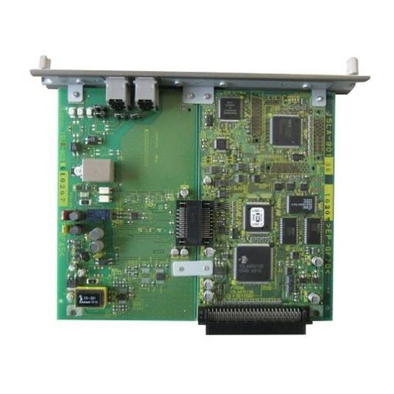
Configuration of the FK-502 board FK-502/Network Fax Service Manual Ver.3.0 6.5.Configuration of the FK-502 board The following shows the configuration of the FK-502. NOTE • When using it as a main line, set SW2 to [LINE-1]. • When using it as a sub line, set SW2 to [LINE-2]. -
Page 127: Communication Control
FK-502/Network Fax Service Manual Ver.3.0 PROTOCOL 7 COMMUNICATION CONTROL 7.1.PROTOCOL 7.1.1 FIF bits of DIS, DTC and DCS FIF Data Configuration List (DIS/DTC) octet Function Contents Default T.37 Internet Fax (Simple mode) Reserved T.38 Real time Internet Fax Third generation mobile network Reserved V.8 ability... - Page 128 PROTOCOL FK-502/Network Fax Service Manual Ver.3.0 octet Function Contents Default Reserved Non-compression mode Error correction mode (ECM) 1: with ECM 0: without ECM ability 0: fixed Reserved Reserved T.6 coding (MMR) ability 1: with MMR 0: without MMR Expansion field...
- Page 129 FK-502/Network Fax Service Manual Ver.3.0 PROTOCOL octet Function Contents Default BTM transfer ability Reserved Character or mixed mode docu- ments ready for Tx (polling) Character mode ability Reserved Mixed mode ability Reserved Expansion field Processible mode (T.505) Digital network ability...
- Page 130 PROTOCOL FK-502/Network Fax Service Manual Ver.3.0 octet Function Contents Default Alternative hashing system num- ber 2 capability Alternative hashing system num- ber 3 capability Reserved T.44 (Mixed Raster Content) T.44 (Mixed Raster Content) T.44 (Mixed Raster Content) Page length maximum strip size for T.44...
- Page 131 FK-502/Network Fax Service Manual Ver.3.0 PROTOCOL octet Function Contents Default Double sided printing capability (alternate mode) Double sided printing capability (continuous mode) Black and white mixed raster content profile (MRCbw) T.45 (run length color encoding) bit(117,118) 0,0=Disable 0,1= Level 1=1.0Mbytes SharedDateMemory capacity 1,0= Level 2=2.0Mbytes...
- Page 132 PROTOCOL FK-502/Network Fax Service Manual Ver.3.0 Contents 3.851/mm --- 10ms 7.71/mm --- 5ms 3.851/mm --- 5ms 7.71/mm --- 5ms 3.851/mm --- 40ms 7.71/mm --- 20ms 3.851/mm --- 20ms 7.71/mm --- 10ms 3.851/mm --- 0ms 7.71/mm --- 0ms *3) T.89 (Application profile for ITU-T T.88)
- Page 133 FK-502/Network Fax Service Manual Ver.3.0 PROTOCOL FIF data configuration list (DCS) octet Function Contents Default T.37 Internet Fax (Simple mode) Reserved T.38 Real time Internet Fax Third generation mobile network Reserved Invalid Invalid Reserved 0: fixed Reception command Transmission speed instruction Refer to *4.
- Page 134 PROTOCOL FK-502/Network Fax Service Manual Ver.3.0 octet Function Contents Default Reserved Non-compression mode Error correction mode (ECM) 1: with ECM instruction 0: without ECM 0: 256 octet Frame size instruction 1: 64 octet Reserved Reserved 1: with MMR T.6 coding (MMR) instruction...
- Page 135 FK-502/Network Fax Service Manual Ver.3.0 PROTOCOL octet Function Contents Default Sub address transmission Password (SID) transmission 0: fixed Reserved BFT transfer DTM transfer EDI transfer Expansion field BTM transfer Reserved 0: fixed Character mode Reserved Mixed mode Reserved Expansion field Processible mode (T.505)
- Page 136 PROTOCOL FK-502/Network Fax Service Manual Ver.3.0 octet Function Contents Default HKM key management selected RSA key management selected Override mode selected HFX40 cipher selected Alternative cipher number 2 selected Alternative cipher number 3 selected HFX40-I hashing selected Expansion field Alternative hashing system number...
- Page 137 FK-502/Network Fax Service Manual Ver.3.0 PROTOCOL octet Function Contents Default 600 pels/25.4mm x 600 lines/ 25.4mm 1200 ples/25.4mm x 1200 lines/ 25.4mm 300 pels/25.4mm x 600 lines/ 25.4mm 400 pels/25.4mm x 800 lines/ 25.4mm 600 pels/25.4mm x 1200 lines/ 25.4mm Color/gray-scale 600 pels/25.4mm x 600/25.4mm...
- Page 138 PROTOCOL FK-502/Network Fax Service Manual Ver.3.0 *4) Transmission speed appointment (bit 11, 12, 13 and 14) Contents 24/V27 ter 48/V27 ter 96/V29 72/V29 144/V17 120/V17 96/V17 72/V17 *5) Minimum scan line time instruction (bit 21, 22 and 23) Contents 20 ms...
-
Page 139: Modem Fallback Sequence
FK-502/Network Fax Service Manual Ver.3.0 PROTOCOL Important Considered to be A4 width when the DIS recording paper width is invalid (1, 1) Becomes a FIF error when the DCS recording paper width is invalid (1, 1). Considered to be unlimited when the DIS recording paper length is invalid (1, 1). - Page 140 PROTOCOL FK-502/Network Fax Service Manual Ver.3.0 • Full-duplex (echo canceler method) / Half-duplex method are regulated (for data / FAX respectively) • 2400, 3000 and 3200 symbols / sec (mandatory) and 2743, 2800 and 3429 symbols / sec (option) QAM synchronous transmission at each symbol rate •...
- Page 141 FK-502/Network Fax Service Manual Ver.3.0 PROTOCOL (2-3) 2nd page transmission termination to communication termination Control channel re-synchronization procedure Source Terminal Image Flags "1" Line Disconnect Data Recipient Terminal ALT E Flags Line Disconnect Flags Note - Some terminals may disconnect the line immediately after sending DCN without sending consecutive 1s.
- Page 142 PROTOCOL FK-502/Network Fax Service Manual Ver.3.0 A. Signal Definition Signal Signal Signal Type Meaning Direction Timing of Transmission Speed Call Called → Function V21(L) Start: after 0.4 seconds after line con- (Call Indicator) display on (300bps) nection from ON condition (in...
- Page 143 FK-502/Network Fax Service Manual Ver.3.0 PROTOCOL Signal Signal Signal Type Meaning Direction Timing of Transmission Speed Call Called Display of V.21(H) Start: When two or more same CM are (Joint Menu) common received ability on Stop: When CJ is received or receives ←...
- Page 144 PROTOCOL FK-502/Network Fax Service Manual Ver.3.0 B. Signal format Preamble: a signal added before each signal when CI, CM and JM signals are sent. Format: 1111111111 +0000000001 (for CI) +0000001111 (for CM and JM) Common format among each signal CI, CM and JM Start Bit (=0) is put at the top and Stop Bit (=1) is put at the end of each octet.
- Page 145 FK-502/Network Fax Service Manual Ver.3.0 PROTOCOL Common signal bit definition 2-1. Call Function (1 octet) Top octet Meaning (Call Function category tag) Defined by ITU-T PSTN multi-media terminal V18 text phone Video tex FAX transmission from the calling terminal FAX reception in the calling terminal...
- Page 146 PROTOCOL FK-502/Network Fax Service Manual Ver.3.0 3st octet Item Meaning (b3, 4 and 5=0, 1, 0 means expanded oct.) V26ter ability disabled / enabled V26bis ability disabled / enabled V23 full-duplex ability disabled / enabled V23 half-duplex ability disabled / enabled V21 ability disabled / enabled 2-3.
- Page 147 FK-502/Network Fax Service Manual Ver.3.0 PROTOCOL (3-2) Phase 2 (Probing) ..V.34 basic setting • Exchange of modulation ability • Measurement of line characteristics (bi-direction) • Determination and exchange of compensation values to line characteristics (compensation values of maximum data rate, transmission level, pre-emphasis (*))
-
Page 148: Index
PROTOCOL FK-502/Network Fax Service Manual Ver.3.0 Bits (LSB-MSB) Value Meaning 3429 symbol / sec transmission Ability to lower the transmission level than a preset value Maximum tolerance of symbol rates between transmission and 21-23 0 to 5 reception 0: 2400, 1:2743, 2:2800, 3:3000, 4:3200, 5:3429 symbol / sec 1=INFO 0 is sent from the CME modem 1664 signal point (33.6K) ability... - Page 149 FK-502/Network Fax Service Manual Ver.3.0 PROTOCOL (3-3) Phase 3 ..Training of the main channel equalizer • Band division full-duplex method • Transmission and reception of Phase 3 signals (S, , PP, TRN) are executed by using parameter values which are determined by exchanging INF Oh. (symbol rate, carrier frequency, pre-emphasis filter and...
- Page 150 PROTOCOL FK-502/Network Fax Service Manual Ver.3.0 MPh (type 0) Bit Assignment Bits (LSB-MSB) Value Meaning 0-16 All bit 1 Bit string for frame synchronization Start bit MP signal type Reserved Maximum transmission rate from the calling modem to the called...
- Page 151 FK-502/Network Fax Service Manual Ver.3.0 PROTOCOL MPh (type 1) Bit Assignment Bits (LSB-MSB) Value Meaning 0-16 All bit 1 Bit string for frame synchronization Start bit MP signal type Reserved Maximum transmission rate from the calling modem to the called...
- Page 152 PROTOCOL FK-502/Network Fax Service Manual Ver.3.0 Bits (LSB-MSB) Value Meaning Start bit 120-135 Pre-coding coefficient h(3) Real Start bit 137-152 Pre-coding coefficient h(3)Imaginary Start bit 154-169 Reserved Start bit 171-186 Fill Bits ▼1 13 and 14 are used when the opposed modem supports up to 1664 points ▼2 Set to 0 on the transmitting modem.
- Page 153 FK-502/Network Fax Service Manual Ver.3.0 PROTOCOL High-speed signal of one frame length which is sent at the end of a series of startup sequence in the selected modulation parameter. Turn-off 128T 35ms Control channel data Data Scrambled 1’s Transmitting modem Main channel 70 ±...
-
Page 154: Telephone Function
TELEPHONE FUNCTION FK-502/Network Fax Service Manual Ver.3.0 7.2.TELEPHONE FUNCTION 7.2.1 TEL/FAX Switching Outline A function to switch telephone and FAX automatically after reception. Depends on Country spec. <Operation> (1) When CNG is not detected for 2 seconds (or 4 seconds, following parameter) after line seizure, this function sends Voice response message 1 and continues CNG detection. - Page 155 FK-502/Network Fax Service Manual Ver.3.0 TELEPHONE FUNCTION Meaning And Address Value Default Note Purpose Time from reception to Tel-Fax voice response 0x0e004e 0: 4 sec Same as the switching transmission bit6 1: 2 sec above parameter (CNG detec- tion waiting...
- Page 156 TELEPHONE FUNCTION FK-502/Network Fax Service Manual Ver.3.0 Blank Page 7-30...
-
Page 157: Explanation Of Functions
FK-502/Network Fax Service Manual Ver.3.0 F-CODE 8 EXPLANATION OF FUNCTIONS 8.1.F-CODE F-code is a function to realize confidential transmission / bulletin board polling / relay transmission by using SUB, SEP and SID signals. To be more specific, a machine which can open “a box” on the memory is called “a F code compliant center machine”... - Page 158 F-CODE FK-502/Network Fax Service Manual Ver.3.0 A. Signal format Contents of signals Item / Signal Name SUB/SEP 0 to 9 only (* and # must not be Characters 0 to 9, * and # used.) Contents Box No. Password No. of digits...
-
Page 159: F-Code Confidential Transmission
FK-502/Network Fax Service Manual Ver.3.0 F-CODE 8.1.1 F-Code Confidential Transmission F-code compliant center machine F-code compliant machine S S S S U U U U B B B B / / / / Confidential Remote entry ( ( ( ( S S S S I I I I D D D ) ) ) ) Box No. - Page 160 F-CODE FK-502/Network Fax Service Manual Ver.3.0 Example of the Protocol Sequence Calling Called Call (NSF)/(CSI)/DIS SID/SUB/(TSI)/DCS (NSF)/(CSI)/DIS (TSI)/DCS...
-
Page 161: F-Code Bulletin Board Polling
FK-502/Network Fax Service Manual Ver.3.0 F-CODE 8.1.2 F-Code Bulletin Board Polling Box No. Local storing F-code compliant center machine F-code compliant machine Bulletin S S S S E E E E P P P P Remote output board Box No. -
Page 162: Transmission Function
TRANSMISSION FUNCTION FK-502/Network Fax Service Manual Ver.3.0 8.2.TRANSMISSION FUNCTION 8.2.1 Original Scan Mode The original scan mode is roughly classified by the regular original scan and the irregular original scan. Regular original Irregular original Mode selection Normal mode Irregular mode... -
Page 163: Reception Function
FK-502/Network Fax Service Manual Ver.3.0 RECEPTION FUNCTION 8.3.RECEPTION FUNCTION 8.3.1 Reduction / Division of Reception Parameters related to reduction / division are set on the [Utility/Counter] > [Administrator Setting] > [Fax Setting] > [TX/RX Setting]. There are two parameters as follows: “Min. -
Page 164: Cassette / Paper Selection
RECEPTION FUNCTION FK-502/Network Fax Service Manual Ver.3.0 A3SEF width at reception Selected paper size / Division operation Original length Optimum =Received Priority Priority Priority Priority Priority Priority Priority Priority paper original size *(1/a) A4LEF A4SEF B4SEF A3SEF 219mm or less... -
Page 165: Closed Reception (Junk Fax)
FK-502/Network Fax Service Manual Ver.3.0 RECEPTION FUNCTION catch the line. (Except the case that the polled transmission documents and bulletin board documents are registered.) Reception • When the reception is performed in the Compulsory memory reception mode, printing is not performed even with recording paper and the reception is performed in memory as the Compulsory memory recep- tion documents. -
Page 166: Management Function
MANAGEMENT FUNCTION FK-502/Network Fax Service Manual Ver.3.0 8.4.MANAGEMENT FUNCTION 8.4.1 Operation without the Key Counter Related settings (1) Transmission without the key counter • Set in the Service menu > [FAX] > [System]. • FAX transmission is inhibited when this setting is set to OFF and there is no key counters (default). -
Page 167: Address Parameter List
FK-502/Network Fax Service Manual Ver.3.0 ADDRESS PARAMETER LIST... - Page 168 ADDRESS PARAMETER LIST FK-502/Network Fax Service Manual Ver.3.0...
- Page 169 FK-502/Network Fax Service Manual Ver.3.0 ADDRESS PARAMETER LIST...
- Page 170 ADDRESS PARAMETER LIST FK-502/Network Fax Service Manual Ver.3.0...
- Page 171 FK-502/Network Fax Service Manual Ver.3.0 ADDRESS PARAMETER LIST...
- Page 172 ADDRESS PARAMETER LIST FK-502/Network Fax Service Manual Ver.3.0...
- Page 173 FK-502/Network Fax Service Manual Ver.3.0 ADDRESS PARAMETER LIST...
- Page 174 ADDRESS PARAMETER LIST FK-502/Network Fax Service Manual Ver.3.0...
- Page 175 FK-502/Network Fax Service Manual Ver.3.0 ADDRESS PARAMETER LIST...
- Page 176 ADDRESS PARAMETER LIST FK-502/Network Fax Service Manual Ver.3.0 9-10...
- Page 177 FK-502/Network Fax Service Manual Ver.3.0 ADDRESS PARAMETER LIST 9-11...
- Page 178 ADDRESS PARAMETER LIST FK-502/Network Fax Service Manual Ver.3.0 9-12...
- Page 179 FK-502/Network Fax Service Manual Ver.3.0 ADDRESS PARAMETER LIST 9-13...
- Page 180 ADDRESS PARAMETER LIST FK-502/Network Fax Service Manual Ver.3.0 9-14...
- Page 181 FK-502/Network Fax Service Manual Ver.3.0 ADDRESS PARAMETER LIST 9-15...
- Page 182 ADDRESS PARAMETER LIST FK-502/Network Fax Service Manual Ver.3.0 9-16...
- Page 183 FK-502/Network Fax Service Manual Ver.3.0 ADDRESS PARAMETER LIST 9-17...
- Page 184 ADDRESS PARAMETER LIST FK-502/Network Fax Service Manual Ver.3.0 9-18...
- Page 185 FK-502/Network Fax Service Manual Ver.3.0 ADDRESS PARAMETER LIST 9-19...
- Page 186 ADDRESS PARAMETER LIST FK-502/Network Fax Service Manual Ver.3.0 9-20...
- Page 187 FK-502/Network Fax Service Manual Ver.3.0 ADDRESS PARAMETER LIST 9-21...
- Page 188 ADDRESS PARAMETER LIST FK-502/Network Fax Service Manual Ver.3.0 9-22...
- Page 189 FK-502/Network Fax Service Manual Ver.3.0 ADDRESS PARAMETER LIST 9-23...
- Page 190 ADDRESS PARAMETER LIST FK-502/Network Fax Service Manual Ver.3.0 9-24...
- Page 191 FK-502/Network Fax Service Manual Ver.3.0 ADDRESS PARAMETER LIST 9-25...
- Page 192 ADDRESS PARAMETER LIST FK-502/Network Fax Service Manual Ver.3.0 9-26...
- Page 193 FK-502/Network Fax Service Manual Ver.3.0 ADDRESS PARAMETER LIST 9-27...
- Page 194 ADDRESS PARAMETER LIST FK-502/Network Fax Service Manual Ver.3.0 9-28...
-
Page 195: Wiring Diagram (Nuc)
FK-502/Network Fax Service Manual Ver.3.0 WIRING DIAGRAM (NUC) 9-29... - Page 196 WIRING DIAGRAM (NUC) FK-502/Network Fax Service Manual Ver.3.0 9-30...
- Page 197 FK-502/Network Fax Service Manual Ver.3.0 WIRING DIAGRAM (NUC) 9-31...
- Page 198 WIRING DIAGRAM (NUC) FK-502/Network Fax Service Manual Ver.3.0 9-32...
- Page 199 FK-502/Network Fax Service Manual Ver.3.0 WIRING DIAGRAM (NUC) 9-33...
- Page 200 WIRING DIAGRAM (NUC) FK-502/Network Fax Service Manual Ver.3.0 9-34...
-
Page 201: Differences Of Functions By Model (As Of Aug.11. 2006)
FK-502/Network Fax Service Manual Ver.3.0 Differences of Functions by Model (as of Aug.11. 2006) 9.3.Differences of Functions by Model (as of Aug.11. 2006) C450/C351/ C352/C300 500/420 750/600 C252/C250 Standard supply* Standard supply* Option Option With HDD With HDD installed: 27GB... - Page 202 Differences of Functions by Model (as of Aug.11. 2006) FK-502/Network Fax Service Manual Ver.3.0 C450/C351/ C352/C300 500/420 750/600 C252/C250 LED display of file Equal size recording Fax Analysis List Network Fax (Internet Fax/IP address Fax) NOTE • * This unit cannot be used if no HDD is installed.
- Page 203 FK-502/Network Fax Service Manual Ver.3.0 How to Enter the Test Mode ....4-2 INDEX INHIBITED COMBINATIONS ..1-17 ADDRESS PARAMETER LIST ..9-1 Initialization ........3-20 Int’l Comm. Function .....3-11 BASIC SPECIFICATIONS ....1-1 BUSY TONE Detection ....3-16 Journal Diagnosis Code Additionl . 3-19 BUSY TONE Detection No.
- Page 204 FK-502/Network Fax Service Manual Ver.3.0 SIGNAL RECEIVING TEST .... 4-4 SIGNAL SENDING TEST ....4-3 Speaker ........... 4-5 System ..........3-6 TEL/FAX Switching ....... 7-28 TELEPHONE FUNCTION ..... 7-28 Test Mode ........4-1 TROUBLESHOOTING ....5-1 V17 EP TONE ....... 3-11 V17 Send Max Speed .....
- Page 205 MEMO...
- Page 206 MEMO...
- Page 208 MS15LBPE3-800...
Need help?
Do you have a question about the FK-502 and is the answer not in the manual?
Questions and answers