Table of Contents
Advertisement
Quick Links
Advertisement
Table of Contents

Related Manuals for Konica Minolta FK-502


Summary of Contents for Konica Minolta FK-502
- Page 1 FK-502...
-
Page 3: Important Notice
Because of possible hazards to an inexperienced person servicing this product as well as the risk of damage to the product, Konica Minolta Business Technologies, INC. (hereafter called the KMBT) strongly recommends that all servicing be performed only by KMBT-trained service technicians. -
Page 4: Safety Warnings
MODIFICATIONS NOT AUTHORIZED BY KONICA MINOLTA BUSINESS TECHNOLOGIES, INC. Konica Minolta brand products are renowned for their high reliability. This reliability is achieved through high- quality design and a solid service network. Product design is a highly complicated and delicate process where numerous mechanical, physical, and electri- cal aspects have to be taken into consideration, with the aim of arriving at proper tolerances and safety factors. - Page 5 SAFETY AND IMPORTANT WARNING ITEMS POWER PLUG SELECTION In some countries or areas, the power plug provided with the product may not fit wall outlet used in the area. In that case, it is obligation of customer engineer (hereafter called the CE) to attach appropriate power plug or power cord set in order to connect the product to the supply.
- Page 6 CHECKPOINTS WHEN PERFORMING ON-SITE SERVICE Konica Minolta brand products are extensively tested before shipping, to ensure that all applicable safety stan- dards are met, in order to protect the customer and CE from the risk of injury. However, in daily use, any electri- cal equipment may be subject to parts wear and eventual failure.
- Page 7 SAFETY AND IMPORTANT WARNING ITEMS Power Plug and Cord WARNING • When using the power cord set (inlet type) that came with this product, make sure the connector is securely inserted in the inlet of the product. When securing measure is provided, secure the cord with the fixture prop- erly.
- Page 8 SAFETY AND IMPORTANT WARNING ITEMS Wiring WARNING • Never use multi-plug adapters to plug multiple power cords in the same out- let. If used, the risk of fire exists. • When an extension cord is required, use a specified one. Current that can flow in the extension cord is limited, so using a too long extension cord may result in fire.
- Page 9 SAFETY AND IMPORTANT WARNING ITEMS Fixing CAUTION • Be sure to lock the caster stoppers. In the case of an earthquake and so on, the product may slide, leading to a injury. Inspection before Servicing CAUTION • Before conducting an inspection, read all relevant documentation (service manual, technical notices, etc.) and proceed with the inspection following the prescribed procedure in safety clothes, using only the prescribed tools.
- Page 10 SAFETY AND IMPORTANT WARNING ITEMS Safety Checkpoints WARNING • Check the exterior and frame for edges, burrs, and other damages. The user or CE may be injured. • Do not allow any metal parts such as clips, staples, and screws to fall into the product.
- Page 11 SAFETY AND IMPORTANT WARNING ITEMS Safety Checkpoints WARNING • Check the interlock switch and actuator for loosening and check whether the interlock functions properly. If the interlock does not function, you may receive an electric shock or be injured when you insert your hand in the product (e.g., for clearing paper jam).
- Page 12 SAFETY AND IMPORTANT WARNING ITEMS Handling of Service Materials CAUTION • Unplug the power cord from the wall outlet. Drum cleaner (isopropyl alcohol) and roller cleaner (acetone-based) are highly flammable and must be handled with care. A risk of fire exists. •...
- Page 13 SAFETY AND IMPORTANT WARNING ITEMS SAFETY INFORMATION IMPORTANT NOTICE The Center for Devices and Radiological Health (CDRH) of the U.S. Food and Drug Administration implemented regulations for laser products manufactured since August 1, 1976. Compliance is mandatory for products mar- keted in the United States.
- Page 14 SAFETY AND IMPORTANT WARNING ITEMS Blank Page...
-
Page 15: Table Of Contents
FK-502 Service Manual Ver.1.0 CONTENTS SAFETY AND IMPORTANT WARNING ITEMS ............S-1 ....................S-1 IMPORTANT NOTICE ......S-1 DESCRIPTION ITEMS FOR DANGER, WARNING AND CAUTION ....................S-2 SAFETY WARNINGS SAFETY INFORMATION ..................S-11 IMPORTANT NOTICE ....................S-11 OUTLINE OF THE DEVICE ..................1-1 1.1.BASIC SPECIFICATIONS ............1-1 1.1.1 General Specifications . -
Page 16: Fk-502 Service Manual Ver
6.1.1 Removal of the FK-502 (in the case of the bizhub C450) ...... -
Page 17: Basic Specifications
• 9000 pages can be stored including all Scan/Box/ Printer/Fax documents. FAX memory backup ........Yes Inside of Hard disk of copier Multiple line connection ........No (10) Communication time ........Level of 2 seconds (Konica Minolta standard A4 chart, 28,800bps) -
Page 18: Scanning Section
BASIC SPECIFICATIONS FK-502 Service Manual Ver.1.0 (11) Resolution conversion Scanner Density Conversion Communication At Sending → inch mm / inch (600 dpi only) inch Communication Density Conversion Print → inch inch At Receiving → inch inch inch inch 1.1.2 Scanning Section Scanning method ......... -
Page 19: Recording Section
FK-502 Service Manual Ver.1.0 BASIC SPECIFICATIONS Automatic reduction at sending ....A3 >> B4, A3 >> A4 and B4 >> A4 • Automatically reduced and sent in accordance with the recording paper size of remote station. Rotation transmission........A4 / Letter size only. LEF documents are rotated by 90 degrees at sending to send it in SEF direction. -
Page 20: Line Connecting Section
BASIC SPECIFICATIONS FK-502 Service Manual Ver.1.0 (15) Multiple copies recording ......No (16) Bypass print ..........Possible to use as an active tray in auto selection mode. (17) Total page counter........Compliant to the copier standards (18) Monitor print ..........No (copy at sending) 1.1.4... -
Page 21: Functional Specifications
FK-502 Service Manual Ver.1.0 FUNCTIONAL SPECIFICATIONS • Files to be displayed are the reception files, trans- mission reservation files, polling reception reserva- tion files and printer files • Light off: There are no files. • Light on: There are files. - Page 22 FUNCTIONAL SPECIFICATIONS FK-502 Service Manual Ver.1.0 Group dial ............ Up to 100 groups. Possible to register group names. up to 500 remote stations per each group by abbrevi- ated numbers only. Dialing of multiple remote stations ....605 remote stations maximum (abbreviated 500 + key pad 100 + manual input E-Mail destination 5) Manual redial ..........
-
Page 23: Transmission
FK-502 Service Manual Ver.1.0 FUNCTIONAL SPECIFICATIONS 1.2.2 Transmission Timer transmission ........24-hour (max.) timer setting is possible. (one station, sequential multi-stations transmission) batch transmission (Timer batch) ....No Timer polling ..........24-hour (max.) timer setting is possible. (one remote station polling and sequential polling reception) No. - Page 24 FUNCTIONAL SPECIFICATIONS FK-502 Service Manual Ver.1.0 • When the FAX memory is full, automatically switched to the quick memory transmission. Mixture of ADF/Platen Advanced Communica- Transmission When the ADF Transmission Platen Transmission Manual Transmission Documents tion Function Printer is Active ▲...
-
Page 25: Polling
FK-502 Service Manual Ver.1.0 FUNCTIONAL SPECIFICATIONS (27) Relay request ..........The relay request by using the F-code (SUB/SID). Appoints the relay BOX No. by using SUB. (28) Relay transmission ........No 1.2.3 Polling Polled transmission ........There is one documents which allows the transmission setting. -
Page 26: Message Reception And Record
FUNCTIONAL SPECIFICATIONS FK-502 Service Manual Ver.1.0 1.2.5 Message Reception and Record Confidential reception ........Reception at the confidential BOX appointed at the F- code (SUB). You can select the SID check on commu- nications. At the time of printing documents received at the confidential BOX, a password to access to the confidential BOX is required. -
Page 27: Various Communication Function
FK-502 Service Manual Ver.1.0 FUNCTIONAL SPECIFICATIONS 1.2.7 Various Communication Function Short protocol ..........No ECM .............Yes • Frame size: 64 byte / 256 byte Communication timer ........Yes • 24 hours maximum. 21 including one for sequential polling timer. Redial waiting ..........Five redial timers maximum Error page resending ........No (becomes the error page redial.) -
Page 28: User Lists / Reports
FUNCTIONAL SPECIFICATIONS FK-502 Service Manual Ver.1.0 • The total number of sent pages, received pages, no. of transmissions and no. of receptions are respectively shown in the management list (for ser- vice). (16) Electronic key counter ......... Yes • The number of transmitted pages to each user. -
Page 29: Other User Functions
FK-502 Service Manual Ver.1.0 FUNCTIONAL SPECIFICATIONS 1.2.9 Other User Functions Fax ID ............Number ID: 20 digits (max.) Header note ..........No Language selection ........Yes 1.2.10 Service Mode Function See the “2 OUTLINE OF OPERATIONS” for details 1.2.11 FAX Service Counter •... -
Page 30: Inhibited Combinations
INHIBITED COMBINATIONS FK-502 Service Manual Ver.1.0 1.3.INHIBITED COMBINATIONS The following show combinations of application functions. Exclusive function (next input) Automatic setting function Text o o o Text/Photo Original Image Type Photo Dot. Matrix o o o Density Single Sided Simplex/... - Page 31 FK-502 Service Manual Ver.1.0 INHIBITED COMBINATIONS Exclusive function (next input) Automatic setting function Text Text/Photo Original Image Type Photo Dot. Matrix Density Single Sided Simplex/ Duplex Double Sided ▼2 Standard Fine Resolution Super Fine Ultra Fine Application Mixed Original ×...
- Page 32 INHIBITED COMBINATIONS FK-502 Service Manual Ver.1.0 Blank Page 1-16...
-
Page 33: Service Operation Mode
FK-502 Service Manual Ver.1.0 SERVICE OPERATION MODE 2 OUTLINE OF OPERATIONS 2.1.SERVICE OPERATION MODE Service Machine Mode Firmware Version Imaging Process Adjustment CS Remote Care System 1 System 2 Counter Life Service Call Counter Maintenance Counter of 1 Outputs Each Mode... - Page 34 SERVICE OPERATION MODE FK-502 Service Manual Ver.1.0 Fax Test Line 1 Signal Send V34 Main CH 2400 - 33600 [bps] Test V34 Control CH CTL CH/INFOc/INFOa/ ToneA/ToneB CM/JM V17t 14400/12000/9600/ 7200 [bps] 9600/7200 [bps] V27ter 4800/2400 [bps] 0/1/2/3/4/5/6/7/8/9/*/#/A/ B/C/D 0/1/2/3/4/5/6/7/8/9...
- Page 35 FK-502 Service Manual Ver.1.0 SERVICE OPERATION MODE RX Max. V17-14400 bps Speed V29-9600 bps V27-4800 bps TxATT PIX TxATT TONE/Proce- dure Signal The setting value are dif- TxATT ferent depending on the country. CED/ANSam TxATT DTMF TxATT Level CD/SED ON...
- Page 36 SERVICE OPERATION MODE FK-502 Service Manual Ver.1.0 CED-DIS 50-150 [ms] DELEY PIX-PMC 50-150 [ms] DELEY TIMER2 EOL-EOL 4.0-25.5 [sec] CFR-PIXWAIT 6.0-25.5 [sec] EOM-PIXWAIT 5.5-25.5 [sec] JM WAIT 6.0-25.5 [sec] Others EMC Function ON/OFF Frame Size at 64,256 ECM TX Coding Ability...
-
Page 37: Service Mode
FK-502 Service Manual Ver.1.0 OUTLINE OF SERVICE MODE 3 SERVICE MODE 3.1.OUTLINE OF SERVICE MODE 3.1.1 Service Mode and Test Mode The service mode is provided in this machine for the purpose of the following operations. And also, the Service Mode includes the Test mode as a menu. -
Page 38: How To Enter The Service Mode
OUTLINE OF SERVICE MODE FK-502 Service Manual Ver.1.0 3.1.3 How to Enter the Service Mode <Operational Procedure> Press [Utility/Counter] button of the control panel. Press [Details Check]. Press [STOP] button and press [0], [0] with keypad. Press [STOP] button and press [0], [1] with keypad. -
Page 39: Function Parameter Setting
FK-502 Service Manual Ver.1.0 FUNCTION PARAMETER SETTING 3.2.FUNCTION PARAMETER SETTING 3.2.1 Modem/NCU <Operational Procedure> See “3.1.3 How to Enter the Service Mode” to display the [Service mode setting] screen. Press the [FAX] key. Press the [Modem/NCU] key. Use the key provided on the left side of the screen to select a menu to be set. - Page 40 FUNCTION PARAMETER SETTING FK-502 Service Manual Ver.1.0 Factory-shipped Parameter Set Value Reference Default Setting 33600 to 2400 [bps] Rx Max.Bit Speed 33600 [bps] (in steps of 2400) 33600 to 2400 [bps] Tx Max.Bit Speed 33600 [bps] (in steps of 2400)
- Page 41 FK-502 Service Manual Ver.1.0 FUNCTION PARAMETER SETTING 2400 • Effective both at the time of sending and receiving • The upper limit value of V.34 maximum bit speed is determined. • Normally you do not need to change the value. In case that a V.34 error frequently occurs, you can attempt to set up SYMB3000 and decrease the symbol rate, for instance.
-
Page 42: System
FUNCTION PARAMETER SETTING FK-502 Service Manual Ver.1.0 3.2.2 System <Operational Procedure> See “3.1.3 How to Enter the Service Mode” to indicate the [Service mode setting] screen. Press the [FAX] key. Press the [System] key. Use the key provided on the left side of the screen to select a menu to be set. - Page 43 FK-502 Service Manual Ver.1.0 FUNCTION PARAMETER SETTING Factory-shipped Referenc Parameter Set Value Default Setting Closed area Rx ON / OFF Display Setting Compulsory Memory ON / OFF Scan Set- Frame Erasure HP 5,10,15[mm] 5[mm] ting Fax Board Watchdog ON / OFF...
- Page 44 FUNCTION PARAMETER SETTING FK-502 Service Manual Ver.1.0 A. Detailed Explanation Closed area Rx • Menu display for closed reception by using F-code for Junk FAXes. Compulsory Memory Rx • Menu display for Compulsory Memory Rx function. Frame Erasure HP • Frame erasure size at scanning •...
- Page 45 FK-502 Service Manual Ver.1.0 FUNCTION PARAMETER SETTING Number of Redials (Error Page) • Counted as a busy redial when the error page redial is busy.
-
Page 46: Communication
FUNCTION PARAMETER SETTING FK-502 Service Manual Ver.1.0 3.2.3 Communication <Operational Procedure> See “3.1.3 How to Enter the Service Mode” to indicate the [Service mode setting] screen. Press the [FAX] key. Press the [Communication] key. Use the key provided on the left side of the screen to select a menu to be set. - Page 47 FK-502 Service Manual Ver.1.0 FUNCTION PARAMETER SETTING Factory- shipped Parameter Set Value Reference Default Setting V8 / V34 Proto- ON / OFF V17 EP TONE ON / OFF V29 EP TONE ON / OFF Protocol V17 Selection ON / OFF Mode “-”...
- Page 48 FUNCTION PARAMETER SETTING FK-502 Service Manual Ver.1.0 Factory- shipped Parameter Set Value Reference Default Setting 4.0 to 25.5[sec] EOL-EOL (Set the value in steps of 13.0[sec] 0.5s.) 6.0 to 25.5[sec] CFR-PIXWAIT (Set the value in steps of 6.0[sec] 0.5s.) TIMER 2 5.5 to 25.5[sec]...
- Page 49 FK-502 Service Manual Ver.1.0 FUNCTION PARAMETER SETTING A. Detailed Explanation V17 EP TONE and V29 EP TONE • Whether the EP tone (Echo Protect: 2100Hz) is added to the top of the training signal. V17 Selection Mode “-” • V.34 is not used when a dash (-) is added at the top of dial number.
-
Page 50: Function Parameter
FUNCTION PARAMETER SETTING FK-502 Service Manual Ver.1.0 3.2.4 Function Parameter <Operational Procedure> See “3.1.3 How to Enter the Service Mode” to indicate the [Service mode setting] screen. Press the [FAX] key. Press the [Function Parameter Setting] key. Select the address and then, enter the address using [A] - [F] key or keypad. -
Page 51: Network
FK-502 Service Manual Ver.1.0 FUNCTION PARAMETER SETTING 3.2.5 Network <Operational Procedure> See “3.1.3 How to Enter the Service Mode” to indicate the [Service mode setting] screen. Press the [FAX] key. Press the [Network] key. Use the key provided on the left side of the screen to select a menu to be set. - Page 52 FUNCTION PARAMETER SETTING FK-502 Service Manual Ver.1.0 Factory-shipped Parameter Set Value Reference Default Setting Receive Signal No. of Times / Time No. of Times Detection Mode Receive Signal 0 to 15[sec] 6 [sec] Detect Time (in steps of 1 sec)
- Page 53 FK-502 Service Manual Ver.1.0 FUNCTION PARAMETER SETTING min. RING OFF Time • MInimum time to recognize ringer interval. For country spec. b: Ring-off time a : To avoid judging “a” as a ring-off time. Response Waiting Time See “3.2.3 Communication”.
-
Page 54: Fax File Format
FUNCTION PARAMETER SETTING FK-502 Service Manual Ver.1.0 3.2.6 Fax File Format The following data can be initialized. • Fax Document ..........All of the fax documents stored in the box are erased. • Box Data ............All of the boxes produced automatically by the F code are erased. -
Page 55: List Output
FK-502 Service Manual Ver.1.0 FUNCTION PARAMETER SETTING 3.2.7 List Output <Operational Procedure> See “3.1.3 How to Enter the Service Mode” to indicate the [Service mode setting] screen. Press the [FAX] key. Press the [List Output] key. Set the parameter setting. -
Page 56: Initialization
FUNCTION PARAMETER SETTING FK-502 Service Manual Ver.1.0 3.2.8 Initialization The following data can be initialized. Select data you want to initialize and press [Yes]. • Fax Function Parameter........ The function set condition is initialized into the Factory Default condition. •... - Page 57 FK-502 Service Manual Ver.1.0 FUNCTION PARAMETER SETTING When a verification message is displayed, press [Yes]. The data selected is initialized. 3-21...
-
Page 58: List Print
LIST PRINT FK-502 Service Manual Ver.1.0 3.3.LIST PRINT The following lists can be output. • Parameter List Output a nonvolatile parameter list. • Service Parameter Output a FAX Service Mode set value list. • Protocol Trace List (Last) The facsimile protocol of the communication which was executed previously is output. - Page 59 FK-502 Service Manual Ver.1.0 LIST PRINT A. Parameter List sample 3-23...
- Page 60 LIST PRINT FK-502 Service Manual Ver.1.0 3-24...
- Page 61 FK-502 Service Manual Ver.1.0 LIST PRINT 3-25...
- Page 62 LIST PRINT FK-502 Service Manual Ver.1.0 3-26...
- Page 63 FK-502 Service Manual Ver.1.0 LIST PRINT 3-27...
- Page 64 LIST PRINT FK-502 Service Manual Ver.1.0 B. Service Parameter List sample 3-28...
- Page 65 FK-502 Service Manual Ver.1.0 LIST PRINT 3-29...
- Page 66 LIST PRINT FK-502 Service Manual Ver.1.0 C. Protocol Trace List (Current) sample 3-30...
- Page 67 FK-502 Service Manual Ver.1.0 LIST PRINT D. Protocol Trace List (Error) sample 3-31...
- Page 68 LIST PRINT FK-502 Service Manual Ver.1.0 E. Fax Setting List sample 3-32...
- Page 69 FK-502 Service Manual Ver.1.0 LIST PRINT 3-33...
- Page 70 LIST PRINT FK-502 Service Manual Ver.1.0 3-34...
- Page 71 FK-502 Service Manual Ver.1.0 LIST PRINT 3-35...
-
Page 72: Fax Counter Check Method
FAX counter check method FK-502 Service Manual Ver.1.0 3.4.FAX counter check method See “3.1.3 How to Enter the Service Mode” to indicate the [Service mode setting] screen. Press the [Counter] key. Press [Counter of Each Mode] key. Press [3] key. -
Page 73: Test Mode
FK-502 Service Manual Ver.1.0 OUTLINE OF THE TEST MODE 4 TEST MODE 4.1.OUTLINE OF THE TEST MODE 4.1.1 Service Mode and Test Mode There is a Service Mode available for this machine. And the Service Mode includes the Test Mode as a menu for the following operation to be conducted. -
Page 74: How To Enter The Test Mode
OUTLINE OF THE TEST MODE FK-502 Service Manual Ver.1.0 4.1.3 How to Enter the Test Mode <Operational Procedure> Press [Utility/Counter] button of the control panel. Press [Details Check]. Press [STOP] button and press [0], [0] with keypad. Press [STOP] button and press [0], [1] with keypad. -
Page 75: Signal Sending Test
FK-502 Service Manual Ver.1.0 SIGNAL SENDING TEST 4.2.SIGNAL SENDING TEST Image information signals, control signals and DTMF can be individually output. Additionally, signal sounds can be monitored by monitor speaker. <Operational Procedure> Press [Signal Sending Test]. Select a test item. -
Page 76: Signal Receiving Test
SIGNAL RECEIVING TEST FK-502 Service Manual Ver.1.0 A. Detailed Explanation Signal Sending Test Signal is output from pressing [Start] to pressing [Stop]. 4.3.SIGNAL RECEIVING TEST Two machines are used for this test. Signal sounds can be monitored by using the monitor speaker. -
Page 77: Ncu Test
FK-502 Service Manual Ver.1.0 NCU TEST 4.4.NCU TEST <Operational Procedure> Press [NCU Test]. Select a test item. Press the [Start] key. Note: In order to move to another test, select the next test item after pressing the [Stop] key. Supplement: •... - Page 78 NCU TEST FK-502 Service Manual Ver.1.0 Blank Page...
-
Page 79: Error Codes
FK-502 Service Manual Ver.1.0 ERROR CODES 5 TROUBLESHOOTING 5.1.ERROR CODES Code No. Category Contents of Error Remarks B0-00 Reserved FAX Board Error 1 (FAX ROM Check B0-01 FAX Board Error Sum Error) FAX Board Error 2 (DPRAM Check B0-02 FAX Board Error... - Page 80 ERROR CODES FK-502 Service Manual Ver.1.0 Code No. Category Contents of Error Remarks Timeout Error due to Nonresponse B1-29 from File System/File Driver during Suspension Process B1-30 MIF Driver Error Driver Soft Error Reception Frame Length Error from B1-31 MIF Driver Error...
- Page 81 FK-502 Service Manual Ver.1.0 ERROR CODES Code No. Category Contents of Error Remarks B1-66 1 Destination Control Reception Resource Check Error Deployment Error of Sending Image B1-67 1 Destination Control Information Serialization Error of Receiving B1-68 1 Destination Control Image...
- Page 82 ERROR CODES FK-502 Service Manual Ver.1.0 Code No. Category Contents of Error Remarks Sending DCN reception in DIS waiting Unexpected command reception in Sending DIS waiting Reserved Reserved Sending DCN reception in CFR/FTT waiting Not used Sending Training failure at 2400bps...
- Page 83 FK-502 Service Manual Ver.1.0 ERROR CODES Code No. Category Contents of Error Remarks Three continuous CRP signal recep- Sending tion Time error between frames at trans- Sending mission Reserved Reserved Reserved Not used Not used FAX-CSRC Host terminal ID inconsistency...
- Page 84 ERROR CODES FK-502 Service Manual Ver.1.0 Code No. Category Contents of Error Remarks Dial Tone detection NG when CML is Call control turned ON at calling Answer tone (CED/DIS) waiting time- Call control out after dialing at calling Call control...
- Page 85 FK-502 Service Manual Ver.1.0 ERROR CODES Code No. Category Contents of Error Remarks Reserved Reserved Reserved Resource check error (line discon- Reception nected due to ongoing communica- tion) Reserved Line disconnection by receive reject Reception function Reserved Reserved Reserved ECM reception...
- Page 86 ERROR CODES FK-502 Service Manual Ver.1.0 Code No. Category Contents of Error Remarks Reserved Reserved Reserved Reserved Reserved Reserved Reserved Reserved Reserved Reception image error (RTN/PIN Reception sending) Not used Not used Three continuous CRP signal recep- Reception tion Not used...
- Page 87 FK-502 Service Manual Ver.1.0 ERROR CODES Code No. Category Contents of Error Remarks Reserved Reserved Reserved Unsatisfactory conditions for confi- F-code reception dential Rx request Unsatisfactory conditions for relay F-code reception request Unsatisfactory conditions for forward- F-code reception ing request...
-
Page 88: Diagnostic Codes
DIAGNOSTIC CODES FK-502 Service Manual Ver.1.0 5.2.DIAGNOSTIC CODES 5.2.1 Outline The diagnostic code is a 17-digit hexadecimal code indicating a communication conditions and status. The diagnostic code is printed on the Activity Report. The purpose of the diagnostic code is to obtain detailed information of communication results and condi- tions so as to analyze communication troubles. - Page 89 FK-502 Service Manual Ver.1.0 DIAGNOSTIC CODES Description Item bit7 bit6 bit5 bit4 bit3 bit2 bit1 bit0 (11) Original 600dpi(V (not (Legal) (Letter) (not Length Spec- used) used) ification/ V_RES Spec- ification (600dpi) (12) Original (not No limits (Legal) (Letter) (not...
- Page 90 DIAGNOSTIC CODES FK-502 Service Manual Ver.1.0 Blank Page 5-12...
-
Page 91: Replacement Procedure
6.1.1 Removal of the FK-502 (in the case of the bizhub C450) In order to replace the FK-502, remove the FK-502 in the following order. NOTE Be sure to check to see if the main power switch is turned off. - Page 92 Replacement of the fax kit for the bizhub C450 FK-502 Service Manual Ver.1.0 6.1.2 Removal of the memory and the lithium battery (in the case of the bizhub C450) Replace the memory and the lithium battery in the following order.
- Page 93 FK-502 Service Manual Ver.1.0 Replacement of the fax kit for the bizhub C450 Open the tab of the memory slot of the control board and remove the memory. NOTE • When reinstalling the memory, take note of the direction in which the DIMM is inserted.
-
Page 94: Removal Of The Speaker (In The Case Of The Bizhub C)
Replacement of the fax kit for the bizhub C450 FK-502 Service Manual Ver.1.0 6.1.3 Removal of the speaker (in the case of the bizhub C450) Replace the speaker in the following order. NOTE Be sure to check to see if the main power switch is turned off. -
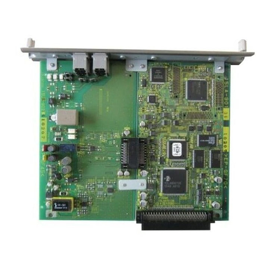
Page 95: Configuration Of The Fk-502 Board
FK-502 Service Manual Ver.1.0 Configuration of the FK-502 board 6.2.Configuration of the FK-502 board The following shows the configuration of the FK-502. FAX Control Board NCU Board... - Page 96 Configuration of the FK-502 board FK-502 Service Manual Ver.1.0 Blank Page...
-
Page 97: Fif Bits Of Dis, Dtc And Dcs
FK-502 Service Manual Ver.1.0 PROTOCOL 7 COMMUNICATION CONTROL 7.1.PROTOCOL 7.1.1 FIF bits of DIS, DTC and DCS FIF Data Configuration List (DIS/DTC) octet Function Contents Default T.37 Internet Fax (Simple mode) Reserved T.38 Real time Internet Fax Third generation mobile network Reserved V.8 ability... - Page 98 PROTOCOL FK-502 Service Manual Ver.1.0 octet Function Contents Default Reserved Non-compression mode Error correction mode (ECM) 1: with ECM 0: without ECM ability 0: fixed Reserved Reserved T.6 coding (MMR) ability 1: with MMR 0: without MMR Expansion field Field Not valid...
- Page 99 FK-502 Service Manual Ver.1.0 PROTOCOL octet Function Contents Default BTM transfer ability Reserved Character or mixed mode docu- ments ready for Tx (polling) Character mode ability Reserved Mixed mode ability Reserved Expansion field Processible mode (T.505) Digital network ability Full-duplex communication abil-...
- Page 100 PROTOCOL FK-502 Service Manual Ver.1.0 octet Function Contents Default Alternative hashing system num- ber 2 capability Alternative hashing system num- ber 3 capability Reserved T.44 (Mixed Raster Content) T.44 (Mixed Raster Content) T.44 (Mixed Raster Content) Page length maximum strip size for T.44...
- Page 101 FK-502 Service Manual Ver.1.0 PROTOCOL octet Function Contents Default Double sided printing capability (alternate mode) Double sided printing capability (continuous mode) Black and white mixed raster content profile (MRCbw) T.45 (run length color encoding) bit(117,118) 0,0=Disable 0,1= Level 1=1.0Mbytes SharedDateMemory capacity 1,0= Level 2=2.0Mbytes...
- Page 102 PROTOCOL FK-502 Service Manual Ver.1.0 Contents 3.851/mm --- 10ms 7.71/mm --- 5ms 3.851/mm --- 5ms 7.71/mm --- 5ms 3.851/mm --- 40ms 7.71/mm --- 20ms 3.851/mm --- 20ms 7.71/mm --- 10ms 3.851/mm --- 0ms 7.71/mm --- 0ms *3) T.89 (Application profile for ITU-T T.88)
- Page 103 FK-502 Service Manual Ver.1.0 PROTOCOL FIF data configuration list (DCS) octet Function Contents Default T.37 Internet Fax (Simple mode) Reserved T.38 Real time Internet Fax Third generation mobile network Reserved Invalid Invalid Reserved 0: fixed Reception command Transmission speed instruction Refer to *4.
- Page 104 PROTOCOL FK-502 Service Manual Ver.1.0 octet Function Contents Default Reserved Non-compression mode Error correction mode (ECM) 1: with ECM instruction 0: without ECM 0: 256 octet Frame size instruction 1: 64 octet Reserved Reserved 1: with MMR T.6 coding (MMR) instruction...
- Page 105 FK-502 Service Manual Ver.1.0 PROTOCOL octet Function Contents Default Sub address transmission Password (SID) transmission 0: fixed Reserved BFT transfer DTM transfer EDI transfer Expansion field BTM transfer Reserved 0: fixed Character mode Reserved Mixed mode Reserved Expansion field Processible mode (T.505)
- Page 106 PROTOCOL FK-502 Service Manual Ver.1.0 octet Function Contents Default HKM key management selected RSA key management selected Override mode selected HFX40 cipher selected Alternative cipher number 2 selected Alternative cipher number 3 selected HFX40-I hashing selected Expansion field Alternative hashing system number...
- Page 107 FK-502 Service Manual Ver.1.0 PROTOCOL octet Function Contents Default 600 pels/25.4mm x 600 lines/ 25.4mm 1200 ples/25.4mm x 1200 lines/ 25.4mm 300 pels/25.4mm x 600 lines/ 25.4mm 400 pels/25.4mm x 800 lines/ 25.4mm 600 pels/25.4mm x 1200 lines/ 25.4mm Color/gray-scale 600 pels/25.4mm x 600/25.4mm...
- Page 108 PROTOCOL FK-502 Service Manual Ver.1.0 *4) Transmission speed appointment (bit 11, 12, 13 and 14) Contents 24/V27 ter 48/V27 ter 96/V29 72/V29 144/V17 120/V17 96/V17 72/V17 *5) Minimum scan line time instruction (bit 21, 22 and 23) Contents 20 ms...
-
Page 109: Modem Fallback Sequence
FK-502 Service Manual Ver.1.0 PROTOCOL Important Considered to be A4 width when the DIS recording paper width is invalid (1, 1) Becomes a FIF error when the DCS recording paper width is invalid (1, 1). Considered to be unlimited when the DIS recording paper length is invalid (1, 1). - Page 110 PROTOCOL FK-502 Service Manual Ver.1.0 • Full-duplex (echo canceler method) / Half-duplex method are regulated (for data / FAX respectively) • 2400, 3000 and 3200 symbols / sec (mandatory) and 2743, 2800 and 3429 symbols / sec (option) QAM synchronous transmission at each symbol rate •...
- Page 111 FK-502 Service Manual Ver.1.0 PROTOCOL (2-3) 2nd page transmission termination to communication termination Control channel re-synchronization procedure Source Terminal Image Flags "1" Line Disconnect Data Recipient Terminal ALT E Flags Line Disconnect Flags Note - Some terminals may disconnect the line immediately after sending DCN without sending consecutive 1s.
- Page 112 PROTOCOL FK-502 Service Manual Ver.1.0 A. Signal Definition Signal Signal Signal Type Meaning Direction Timing of Transmission Speed Call Called → Function V21(L) Start: after 0.4 seconds after line con- (Call Indicator) display on (300bps) nection from ON condition (in...
- Page 113 FK-502 Service Manual Ver.1.0 PROTOCOL Signal Signal Signal Type Meaning Direction Timing of Transmission Speed Call Called Display of V.21(H) Start: When two or more same CM are (Joint Menu) common received ability on Stop: When CJ is received or receives ←...
- Page 114 PROTOCOL FK-502 Service Manual Ver.1.0 B. Signal format Preamble: a signal added before each signal when CI, CM and JM signals are sent. Format: 1111111111 +0000000001 (for CI) +0000001111 (for CM and JM) Common format among each signal CI, CM and JM Start Bit (=0) is put at the top and Stop Bit (=1) is put at the end of each octet.
- Page 115 FK-502 Service Manual Ver.1.0 PROTOCOL Common signal bit definition 2-1. Call Function (1 octet) Top octet Meaning (Call Function category tag) Defined by ITU-T PSTN multi-media terminal V18 text phone Video tex FAX transmission from the calling terminal FAX reception in the calling terminal...
- Page 116 PROTOCOL FK-502 Service Manual Ver.1.0 3st octet Item Meaning (b3, 4 and 5=0, 1, 0 means expanded oct.) V26ter ability disabled / enabled V26bis ability disabled / enabled V23 full-duplex ability disabled / enabled V23 half-duplex ability disabled / enabled V21 ability disabled / enabled 2-3.
- Page 117 FK-502 Service Manual Ver.1.0 PROTOCOL (3-2) Phase 2 (Probing) ..V.34 basic setting • Exchange of modulation ability • Measurement of line characteristics (bi-direction) • Determination and exchange of compensation values to line characteristics (compensation values of maximum data rate, transmission level, pre-emphasis (*))
- Page 118 PROTOCOL FK-502 Service Manual Ver.1.0 Bits (LSB-MSB) Value Meaning 3429 symbol / sec transmission Ability to lower the transmission level than a preset value Maximum tolerance of symbol rates between transmission and 21-23 0 to 5 reception 0: 2400, 1:2743, 2:2800, 3:3000, 4:3200, 5:3429 symbol / sec 1=INFO 0 is sent from the CME modem 1664 signal point (33.6K) ability...
- Page 119 FK-502 Service Manual Ver.1.0 PROTOCOL (3-3) Phase 3 ..Training of the main channel equalizer • Band division full-duplex method • Transmission and reception of Phase 3 signals (S, , PP, TRN) are executed by using parameter values which are determined by exchanging INF Oh. (symbol rate, carrier frequency, pre-emphasis filter and...
- Page 120 PROTOCOL FK-502 Service Manual Ver.1.0 MPh (type 0) Bit Assignment Bits (LSB-MSB) Value Meaning 0-16 All bit 1 Bit string for frame synchronization Start bit MP signal type Reserved Maximum transmission rate from the calling modem to the called 20-23 1 to 14 modem (x2400) ▼1...
- Page 121 FK-502 Service Manual Ver.1.0 PROTOCOL MPh (type 1) Bit Assignment Bits (LSB-MSB) Value Meaning 0-16 All bit 1 Bit string for frame synchronization Start bit MP signal type Reserved Maximum transmission rate from the calling modem to the called 20-23 1 to 14 modem (x2400) ▼1...
- Page 122 PROTOCOL FK-502 Service Manual Ver.1.0 Bits (LSB-MSB) Value Meaning Start bit 120-135 Pre-coding coefficient h(3) Real Start bit 137-152 Pre-coding coefficient h(3)Imaginary Start bit 154-169 Reserved Start bit 171-186 Fill Bits ▼1 13 and 14 are used when the opposed modem supports up to 1664 points ▼2 Set to 0 on the transmitting modem.
- Page 123 FK-502 Service Manual Ver.1.0 PROTOCOL High-speed signal of one frame length which is sent at the end of a series of startup sequence in the selected modulation parameter. Turn-off 128T 35ms Control channel data Data Scrambled 1’s Transmitting modem Main channel 70 ±...
-
Page 124: Telephone Function
TELEPHONE FUNCTION FK-502 Service Manual Ver.1.0 7.2.TELEPHONE FUNCTION 7.2.1 TEL/FAX Switching Outline A function to switch telephone and FAX automatically after reception. Depends on Country spec. <Operation> (1) When CNG is not detected for 2 seconds (or 4 seconds, following parameter) after line seizure, this function sends Voice response message 1 and continues CNG detection. - Page 125 FK-502 Service Manual Ver.1.0 TELEPHONE FUNCTION Meaning And Address Value Default Note Purpose Time from reception to Tel-Fax voice response 0x0e004e 0: 4 sec Same as the switching transmission bit6 1: 2 sec above parameter (CNG detec- tion waiting time 1)
- Page 126 TELEPHONE FUNCTION FK-502 Service Manual Ver.1.0 Blank Page 7-30...
- Page 127 FK-502 Service Manual Ver.1.0 F-CODE 8 EXPLANATION OF FUNCTIONS 8.1.F-CODE F-code is a function to realize confidential transmission / bulletin board polling / relay transmission by using SUB, SEP and SID signals. To be more specific, a machine which can open “a box” on the memory is called “a F code compliant center machine”...
- Page 128 F-CODE FK-502 Service Manual Ver.1.0 A. Signal format Contents of signals Item / Signal Name SUB/SEP 0 to 9 only (* and # must not be Characters 0 to 9, * and # used.) Contents Box No. Password No. of digits...
-
Page 129: F-Code Confidential Transmission
FK-502 Service Manual Ver.1.0 F-CODE 8.1.1 F-Code Confidential Transmission F-code compliant center machine F-code compliant machine S S S S U U U U B B B B / / / / Confidential Remote entry ( ( ( ( S S S S I I I I D D D ) ) ) ) Box No. - Page 130 F-CODE FK-502 Service Manual Ver.1.0 Example of the Protocol Sequence Calling Called Call (NSF)/(CSI)/DIS SID/SUB/(TSI)/DCS (NSF)/(CSI)/DIS (TSI)/DCS...
-
Page 131: F-Code Bulletin Board Polling
FK-502 Service Manual Ver.1.0 F-CODE 8.1.2 F-Code Bulletin Board Polling Box No. Local storing F-code compliant center machine F-code compliant machine Bulletin S S S S E E E E P P P P Remote output board Box No. Printing Deletion Box No. -
Page 132: Transmission Function
TRANSMISSION FUNCTION FK-502 Service Manual Ver.1.0 8.2.TRANSMISSION FUNCTION 8.2.1 Original Scan Mode The original scan mode is roughly classified by the regular original scan and the irregular original scan. Regular original Irregular original Mode selection Normal mode Irregular mode Default setting... -
Page 133: Reception Function
FK-502 Service Manual Ver.1.0 RECEPTION FUNCTION 8.3.RECEPTION FUNCTION 8.3.1 Reduction / Division of Reception Parameters related to reduction / division are set on the [Utility/Counter] > [Administrator Setting] > [Fax Setting] > [TX/RX Setting]. There are two parameters as follows: “Min. -
Page 134: Cassette / Paper Selection
RECEPTION FUNCTION FK-502 Service Manual Ver.1.0 A3SEF width at reception Selected paper size / Division operation Original length Optimum =Received Priority Priority Priority Priority Priority Priority Priority Priority paper original size *(1/a) A4LEF A4SEF B4SEF A3SEF 219mm or less / a %... -
Page 135: Closed Reception (Junk Fax)
FK-502 Service Manual Ver.1.0 RECEPTION FUNCTION catch the line. (Except the case that the polled transmission documents and bulletin board documents are registered.) Reception • When the reception is performed in the Compulsory memory reception mode, printing is not performed even with recording paper and the reception is performed in memory as the Compulsory memory recep- tion documents. -
Page 136: Management Function
MANAGEMENT FUNCTION FK-502 Service Manual Ver.1.0 8.4.MANAGEMENT FUNCTION 8.4.1 Operation without the Key Counter Related settings (1) Transmission without the key counter • Set in the Service menu > [FAX] > [System]. • FAX transmission is inhibited when this setting is set to OFF and there is no key counters (default). - Page 137 FK-502 Service Manual Ver.1.0 ADDRESS PARAMETER LIST...
- Page 138 ADDRESS PARAMETER LIST FK-502 Service Manual Ver.1.0...
- Page 139 FK-502 Service Manual Ver.1.0 ADDRESS PARAMETER LIST...
- Page 140 ADDRESS PARAMETER LIST FK-502 Service Manual Ver.1.0...
- Page 141 FK-502 Service Manual Ver.1.0 ADDRESS PARAMETER LIST...
- Page 142 ADDRESS PARAMETER LIST FK-502 Service Manual Ver.1.0...
- Page 143 FK-502 Service Manual Ver.1.0 ADDRESS PARAMETER LIST...
- Page 144 ADDRESS PARAMETER LIST FK-502 Service Manual Ver.1.0...
- Page 145 FK-502 Service Manual Ver.1.0 ADDRESS PARAMETER LIST...
- Page 146 ADDRESS PARAMETER LIST FK-502 Service Manual Ver.1.0 9-10...
- Page 147 FK-502 Service Manual Ver.1.0 ADDRESS PARAMETER LIST 9-11...
- Page 148 ADDRESS PARAMETER LIST FK-502 Service Manual Ver.1.0 9-12...
- Page 149 FK-502 Service Manual Ver.1.0 ADDRESS PARAMETER LIST 9-13...
- Page 150 ADDRESS PARAMETER LIST FK-502 Service Manual Ver.1.0 9-14...
- Page 151 FK-502 Service Manual Ver.1.0 ADDRESS PARAMETER LIST 9-15...
- Page 152 ADDRESS PARAMETER LIST FK-502 Service Manual Ver.1.0 9-16...
- Page 153 FK-502 Service Manual Ver.1.0 ADDRESS PARAMETER LIST 9-17...
- Page 154 ADDRESS PARAMETER LIST FK-502 Service Manual Ver.1.0 9-18...
- Page 155 FK-502 Service Manual Ver.1.0 WIRING DIAGRAM (NUC) 9-19...
- Page 156 WIRING DIAGRAM (NUC) FK-502 Service Manual Ver.1.0 9-20...
- Page 157 FK-502 Service Manual Ver.1.0 WIRING DIAGRAM (NUC) 9-21...
- Page 158 WIRING DIAGRAM (NUC) FK-502 Service Manual Ver.1.0 9-22...
- Page 159 FK-502 Service Manual Ver.1.0 WIRING DIAGRAM (NUC) 9-23...
- Page 160 WIRING DIAGRAM (NUC) FK-502 Service Manual Ver.1.0 9-24...
-
Page 161: Table Of Contents
Receive Signal Detection Mode ...3-16 Frame Erasure HP ......3-7 Recording Section ......1-3 Function Parameter ...... 3-14 Reduction / Division of Reception ..8-7 FUNCTION Removal of the FK-502 ....6-1 PARAMETER SETTING ..3-3 Removal of the memory and the lithium battery ...6-2 Index-1... - Page 162 FK-502 Service Manual Ver.1.0 Removal of the speaker ....6-4 Reports ........1-12 Scanning Section ......1-2 Service Mode ......... 3-1 SERVICE OPERATION MODE ..2-1 Service Parameter ....... 3-22 SIGNAL RECEIVING TEST ... 4-4 SIGNAL SENDING TEST ....4-3 Speaker ..........
- Page 164 MS15LBE1-0800...
- Page 165 Contents Default Setting Address Item North Amer- bit7 bit6 bit5 bit4 bit3 bit2 bit1 bit0 Japan Europe Utility Mode Redial interval 0b0000 Redial interval 0x03 0x03 0x03 (0-3) (min, HEX, 0 - 15) Utility Mode No. of busy redials 0b0001 No.
- Page 166 Contents Default Setting Address Item North Amer- bit7 bit6 bit5 bit4 bit3 bit2 bit1 bit0 Japan Europe File holding time Debug mode 0000:12 hours Utility Mode 0b000f Restored transmission 0:OFF 0001:24 hours 0x00 0x00 0x00 (0-3) 1:ON(3min) 0010:48 hours 0011:72 hours 0b0010 Inter-station timer HEX (unit: second)(00 - ffh)(00 means 03)
- Page 167 Contents Default Setting Address Item North Amer- bit7 bit6 bit5 bit4 bit3 bit2 bit1 bit0 Japan Europe No. of good judgment error lines (HEX) 0e0002 No. of error lines-good 0x40 0x40 0x40 VeryGoodErrorNum<No. of error linesGoodErrorNum, RTP is transmitted No. of bad judgment error lines (HEX) 0e0003 No.
- Page 168 Contents Default Setting Address Item North Amer- bit7 bit6 bit5 bit4 bit3 bit2 bit1 bit0 Japan Europe 0e0018 Ci signal transmission time Ci signal transmission time (Unit: 100 ms, HEX) 0x05 0x05 0x05 High-speed signal transmission waiting delay timer 0e0019 High-speed signal transmission waiting delay timer 0x37 0x37...
- Page 169 Contents Default Setting Address Item North Amer- bit7 bit6 bit5 bit4 bit3 bit2 bit1 bit0 Japan Europe PB OFF time integration PB ON time integration 0e004f Tone detection time (PB) 0x55 0x55 0x55 0to15 (x10ms) (50ms if 0) 0to15 (x10ms) (50ms if 0) Waiting event from modem/Response waiting timeout time (x10sec, HEX) 0e0050 Time for modem response waiting timeout...
- Page 170 Contents Default Setting Address Item North Amer- bit7 bit6 bit5 bit4 bit3 bit2 bit1 bit0 Japan Europe TEL/FAX switching mode Utility Mode (4,5) 0e0095 Tel-Fax switching 00: No 0x00 0x00 0x00 10: Normal (RBT transmission) RBT format 000: None Utility Mode 001: Japan CED transmitted Special Setting...
- Page 171 Contents Default Setting Address Item North Amer- bit7 bit6 bit5 bit4 bit3 bit2 bit1 bit0 Japan Europe FP JBIG of JBIG optional L0 optional LO size is function 0e00a5 JBIG parameter used for reduction 0x01 0x01 0x01 0: No 0: No 1: Yes 1: Yes 0x00...
- Page 172 Contents Default Setting Address Item North Amer- bit7 bit6 bit5 bit4 bit3 bit2 bit1 bit0 Japan Europe 0e00bc 1st dial tone instantaneous break detection time Instantaneous shutdown detection time (unit: 20 ms, HEX) or tone detection frequency (times, HEX) 0x00 0x00 0x00 0e00bd...
- Page 173 Contents Default Setting Address Item North Amer- bit7 bit6 bit5 bit4 bit3 bit2 bit1 bit0 Japan Europe 0e00d3 Ringer detection frequency upper limits Ringer detection frequency upper limit (unit: 1 Hz, HEX) 0x46 0x46 0x46 0e00d4 Ringer detection frequency lower limits Ringer detection frequency lower limit (unit: 1 Hz, HEX) 0x0c 0x0c...
- Page 174 Contents Default Setting Address Item North Amer- bit7 bit6 bit5 bit4 bit3 bit2 bit1 bit0 Japan Europe DC-LOOP check Utility Mode Spe- 00: No 0e00ea DCLOOP check mode 0x00 0x00 0x00 cial Setting (6,7) 01:ph.A only 10: Always 0e00eb DCLOOP waiting time DCLOOP waiting time (unit: 100 ms, HEX) 0x00 0x00...
- Page 175 Contents Default Setting Address Item North Amer- bit7 bit6 bit5 bit4 bit3 bit2 bit1 bit0 Japan Europe Automatic judg- Normal/number display automatic line determina- ment function 0e0100 V23 signal detection waiting time when judged (x1 sec, HEX) 0x83 0x00 0x00 tion function 0:OFF 1:ON...
- Page 176 Contents Default Setting Address Item North Amer- bit7 bit6 bit5 bit4 bit3 bit2 bit1 bit0 Japan Europe 0f0008 Reception speed ability[1] V.17-144 V.17-120 V.17-96 V.17-72 V.33-144 V.33-120 (TCM-96) (TCM-72) 0xfc 0xfc 0xfc 0f0009 Reception speed ability[2] V.34-192 V.34-168 V.34-144 V.34-120 V.34-96 V.34-72 V.34-48...
- Page 177 Contents Default Setting Address Item North Amer- bit7 bit6 bit5 bit4 bit3 bit2 bit1 bit0 Japan Europe 100009 Transmission speed instruction[2] V.34-192 V.34-168 V.34-144 V.34-120 V.34-96 V.34-72 V.34-48 V.34-24 0xff 0xff 0xff 10000a Transmission speed instruction[3] V.34-336 V.34-312 V.34-288 V.34-264 V.34-240 V.34-216 0x3f...
- Page 178 Contents Default Setting Address Item North Amer- bit7 bit6 bit5 bit4 bit3 bit2 bit1 bit0 Japan Europe Broadcast result Output order of Transmission Printing during Utility Mode report output journal transmis- Diagnostic code result report auxiliary power (3 - 5) method sion result reser- display...
- Page 179 Contents Default Setting Address Item North Amer- bit7 bit6 bit5 bit4 bit3 bit2 bit1 bit0 Japan Europe Utility Mode Spe- Letter cial Setting 130008 Rotation setting HP 0:No 0:No 0:No 0x03 0x03 0x03 (0,1) 1:Yes 1:Yes 1:Yes Time until auto reset 130009 Reserved area 0x00...
- Page 180 Contents Default Setting Address Item North Amer- bit7 bit6 bit5 bit4 bit3 bit2 bit1 bit0 Japan Europe Utility Mode 13006d Upper limit for redial interval setting range (No. of times, HEX) 0x01 0x01 0x01 Utility Mode 13006e Lower limit for redial interval setting range (No.
Need help?
Do you have a question about the FK-502 and is the answer not in the manual?
Questions and answers