Table of Contents
Advertisement
Quick Links
Applied Machines: C287/C227/367/287/227
COLOR MFP: 28 ppm/22 ppm
MFP: 36 ppm/28 ppm/22 ppm
Product Code: A797/A798/A789/A7AH/A7AK
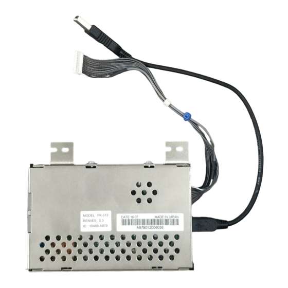
1. Accessory parts
No.
Name
1. Fax kit
2. Harness
3. Modular
cable
4. USB cable
5. Ferrite core
*
6. Clamp
7. Wire saddle
8. Screw
FK-513
INSTALLATION MANUAL
Shape
Q'ty
1
1
1
1
1
2
2
2
Fax Kit
No.
Name
9. Label
(Super G3
*
label)
10. Label
*
11. Installation
manual
*
Varies depending on the applicable marketing
area
Keep this bag away from babies and
children. Do not use in cribs, beds,
carriages, or playpens.
The thin film may cling to nose and
mouth and prevent breathing. This bag is
not a toy.
Note:
• This manual provides the illustrations of the
accessory parts and machine that may be
slightly different in shape from yours. In that
case, instead of the illustrations, use the
appearance of your machine to follow the
installation procedure. This does not cause any
significant change or problem with the proce-
dure.
• If none of the later steps instruct you to use the
parts including screw and cover that you
removed following the instructions described in
this manual, discard them.
E-1
Shape
Q'ty
1
1set
1 set
A879-9551-00
Advertisement
Table of Contents

Related Manuals for Konica Minolta FK-513


Summary of Contents for Konica Minolta FK-513
- Page 1 FK-513 Fax Kit INSTALLATION MANUAL Applied Machines: C287/C227/367/287/227 COLOR MFP: 28 ppm/22 ppm MFP: 36 ppm/28 ppm/22 ppm Product Code: A797/A798/A789/A7AH/A7AK 1. Accessory parts Name Shape Q’ty Name Shape Q’ty 9. Label (Super G3 1. Fax kit label) 10. Label 1set 2.
- Page 2 2. Installation procedures (5) Remove the metal plate. (Three screws) <Installations to models C287/C227> Follow the installation procedures starting on page E-2. <Installations to models 367/287/227> Follow the installation procedures starting on page E-4. <Installations to models C287/C227> (1) Turn OFF the power switch and unplug the power cord from the power outlet.
- Page 3 (9) Attach the supplied two wire saddles. (11) Connect the connectors of the supplied har- ness and USB cable to the Fax kit. (12) Route the harness and USB cable inside the two wire saddles installed in step (9). Note: Make sure that the blue cable tie securing the har- ness is positioned as shown in the illustration.
- Page 4 (14) Connect the USB cable to the port shown in the (4) Attach the supplied two wire saddles. illustration. (15) To install the covers and other parts removed in steps (2) to (5), reverse the removal procedure. (16) Go to <Installation of the ferrite core> on page E-6.
- Page 5 (6) Route the supplied harness through the wire (9) Install the rear cover and install the toner filter. saddles installed in step (4) and insert the con- a) Attach the rear cover. (Five screws) nector into the Fax kit. Note: Note: Fasten the mounting screws in the order from [1] Make sure that the white cable tie securing the...
- Page 6 <Installation of the ferrite core> <Connecting the modular cable> (1) Connect the supplied modular cable to the LINE Note: port. • Perform the steps only when a Fax Kit which has a ferrite core bundled for applicable mar- Note: keting area is installed. •...
- Page 7 3. Configuration procedures <Affixing the labels> (1) Affix the supplied label to the position shown <Setting the FAX> below. (1) Plug the power cord into the power outlet and <C287/C227> turn ON the power switch. (2) Display the Service Mode screen. (For details of how to display the Service Mode screen, see the service manual.) (3) Touch “System 2.”...
- Page 8 <Caution when performing dial transfer> (12) Use the key to select the Target Area (Refer to the list below). After setting the country code, dialing operations may be selected after the switchboard dial tone is Country code setting for FAX detected depending on the destination.
Need help?
Do you have a question about the FK-513 and is the answer not in the manual?
Questions and answers