Advertisement
Quick Links
Applied Machines: C658/C558/C458/C368/C308/C258
COLOR MFP: 65 ppm/55 ppm/45 ppm/36 ppm/30 ppm/25 ppm
Product Code: A79J/A79K/A79M/A7PU/A7PY/A7R0
1. Accessory parts
No.
Name
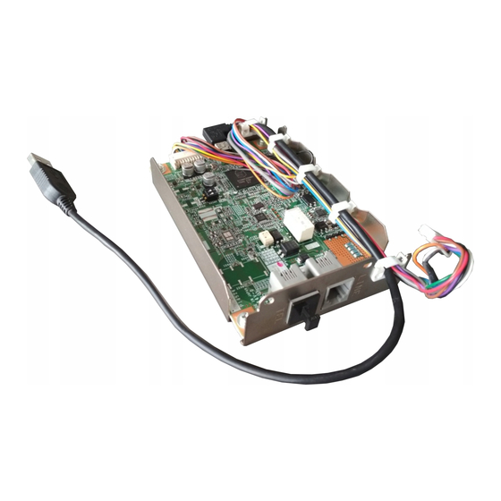
1. Fax kit
2. Gasket
*1*2
3. Modular cable
*3
4. Ferrite core
*4
5. Modular cover
6. Label (Super
*4
G3 label)
7. Label
*4
8. Installation
manual
FK-514
INSTALLATION MANUAL
Shape
Q'ty
1
2
1
1
1
1
1 set
1 set
Fax Kit
*1
This part is used only when installing this option
to models C658/C558/C458.
*2
When installing a Line 1, use the two gaskets.
When installing a Line 2, use three of the four
gaskets supplied with the Fax Kits for the Line 1
and Line 2.
*3
Depending on the applicable marketing area, the
modular cable may have a ferrite core.
*4
Not included depending on the applicable mar-
keting area.
Keep this bag away from babies and
children. Do not use in cribs, beds,
carriages, or playpens.
The thin film may cling to nose and
mouth and prevent breathing. This bag is
not a toy.
Note:
• This manual provides the illustrations of the
accessory parts and machine that may be
slightly different in shape from yours. In that
case, instead of the illustrations, use the
appearance of your machine to follow the
installation procedure. This does not cause any
significant change or problem with the proce-
dure.
• If none of the later steps instruct you to use the
parts including screw and cover that you
removed following the instructions described in
this manual, discard them.
2. Installation procedures
<Installations to models C658/C558/C458>
Follow the installation procedures starting on page
E-2.
<Installations to models C368/C308/C258>
Follow the installation procedures starting on page
E-9.
E-1
A883-9552-00
Advertisement

Related Manuals for Konica Minolta FK-514


Summary of Contents for Konica Minolta FK-514
-
Page 1: Installation Procedures
FK-514 Fax Kit INSTALLATION MANUAL Applied Machines: C658/C558/C458/C368/C308/C258 COLOR MFP: 65 ppm/55 ppm/45 ppm/36 ppm/30 ppm/25 ppm Product Code: A79J/A79K/A79M/A7PU/A7PY/A7R0 1. Accessory parts This part is used only when installing this option to models C658/C558/C458. Name Shape Q’ty When installing a Line 1, use the two gaskets. - Page 2 <Installations to models C658/C558/C458> (5) Make sure that the fax kit switch keys are placed in positions as shown in “Line 1” below. (1) Turn OFF the power switch and unplug the Note: power cord from the power outlet. When installing a second fax kit, flip the fax kit (2) Open the rear right cover.
- Page 3 <Only when adding Line 2> (9) Connect each of the two connectors of the fax kit (7) Attach one supplied gasket on the top of the fax to the corresponding port of FAX1. kit (Line 1) as shown in the illustration. Note: When installing a second fax kit, connect the two connectors to respective ports of FAX2.
- Page 4 (10) Route the fax kit harness and the USB cable as (11) Reinstall the connector cover that has been shown in the illustration below. removed in step (3).(One screw) <Line 1> Note: • Fit the connector cover protrusion in the portion of the machine shown in the illustration below.
- Page 5 <Only when using the telephone line> <When using the Paper Feed Cabinet PC-415/PC- 215/PC-115 or desk DK-510> (2) Insert the modular cable of the telephone line to the modular jack (TEL) of the fax kit (Line 1). (5) Perform the following steps. a) Remove the rear right cover from the paper <Only when installing line 2>...
- Page 6 d) Route the cable through the notch and attach <Only when using the telephone line> the rear right cover. (Two screws) (3) Perform the following steps. a) Attach the supplied ferrite core to the position of the modular cable of the telephone shown in the illustration.
- Page 7 c) House the ferrite core of the modular cable in b) House the ferrite core of the modular cable in the machine. the machine. Note: Note: • Pass the protrusion shown in the illustration Pass the cable wound around the ferrite core below through the cable wound around the fer- through the protrusion.
- Page 8 <When using the Paper Feed Cabinet PC-415/PC- d) Route the cable through the notch and attach 215/PC-115 or desk DK-510> the rear right cover. (Two screws) (6) Perform the following steps. a) Remove the rear right cover from the paper feed cabinet or desk.
- Page 9 <Installations to models C368/C308/C258> (5) Make sure that the fax kit switch keys are placed in positions as shown in “Line 1” below. (1) Turn OFF the power switch and unplug the Note: power cord from the power outlet. When installing a second fax kit, flip the fax kit (2) Open the rear right cover.
- Page 10 Note: (8) Route the fax kit harness and the USB cable as When installing a second fax kit, insert the sup- shown in the illustration below. plied modular cover into the modular jack (TEL) for <Line 1> “Line-2.” (7) Connect each of the two connectors of the fax kit to the corresponding port of FAX1.
- Page 11 (9) Reinstall the connector cover that has been (4) Place the modular cable in the harness guide. removed in step (3).(One screw) Note: • Fit the connector cover protrusion in the portion of the machine shown in the illustration below. •...
- Page 12 b. When the ferrite core is installed to the sup- b) Remove the knockout from the rear right cover using nippers. plied modular cable (1) Connect the supplied modular cable in the mod- ular jack (LINE) of the fax kit (Line 1). Note: If the user is connected with a key telephone sys- tem or a private branch exchange (PBX), do not...
- Page 13 <Only when using the telephone line> c) House the ferrite core of the modular cable in the machine. (3) Perform the following steps. Note: a) Attach the supplied ferrite core to the position of • Pass the protrusion shown in the illustration the modular cable of the telephone shown in below through the cable wound around the fer- the illustration.
- Page 14 b) House the ferrite core of the modular cable in <When using the Paper Feed Cabinet PC-410/PC- the machine. 210/PC-110 or desk DK-510> Note: (6) Perform the following steps. Pass the cable wound around the ferrite core a) Remove the rear right cover from the paper through the protrusion.
-
Page 15: Configuration Procedures
d) Route the cable through the notch and attach (6) Touch “END” and touch “Exit.” the rear right cover. (Two screws) (7) Turn OFF and ON the power switch. Note: • When displayed the Service Mode screen, be sure to turn OFF the power switch after exiting the Service Mode screen and wait for 10 sec- onds or more before turning ON. - Page 16 (19) Touch “END.” (7) Turn OFF and ON the power switch. (20) Touch “Exit” on the Service Mode screen. Note: (21) Perform the sending and receiving tests • When displayed the Service Mode screen, be between the Machine and either the store sure to turn OFF the power switch after exiting which offers the service or the local retailer, to the Service Mode screen and wait for 10 sec-...
Need help?
Do you have a question about the FK-514 and is the answer not in the manual?
Questions and answers