Sign In
Upload
Manuals
Brands
Xerox Manuals
Printer
5400N - Phaser B/W Laser Printer
Xerox 5400N - Phaser B/W Laser Printer Manuals
Manuals and User Guides for Xerox 5400N - Phaser B/W Laser Printer. We have
2
Xerox 5400N - Phaser B/W Laser Printer manuals available for free PDF download: Service Quick Reference Manual, Technical Instructions
Xerox 5400N - Phaser B/W Laser Printer Service Quick Reference Manual (503 pages)
Quick Reference Guide
Brand:
Xerox
| Category:
Printer
| Size: 10.24 MB
Table of Contents
Table of Contents
12
Users Safety Summary
4
Service Safety Summary
7
Table of Contents
12
List of Figures
20
General Information
30
Figure 1 Machine Orientation
30
Figure 2 Front View
33
Figure 3 Rear View
33
Parts of the Printer
33
Printer Components
33
Figure 4 View from Right Front
34
Figure 5 View from Left Rear
34
Printer Options
34
Control Panel
35
Figure 6 Control Panel
35
Display Screen
36
Figure 7 Rear Panel
37
Rear Panel
37
Figure 8 Print Engine Assemblies, Sensors and Interlock Locations
38
Print Engine Assemblies
38
Figure 9 FRU Assemblies, Sensors and Interlock Locations 2
39
Figure 10 FRU Assemblies, Sensors and Interlock Locations 3 - Detack Saw, Registration & Bias Transfer Rollers and Paper Transport Assembly
40
Figure 11 FRU Assemblies, Sensors and Interlock Locations 4 - Fuser Area
41
Figure 12 FRU Assemblies, Sensors and Interlock Locations 5 - Main Drive
42
Figure 14 Paper Path Flow
44
Paper Path Information
44
Figure 15 Paper Path Components
45
Printer Specifications
46
RAM and Printer Capabilities
46
Table 1 Memory Upgrades
46
Basic Specifications
47
Electrical Specifications
47
Table 2 Basic Specifications
47
Table 3 Electrical Specifications
47
Mechanical Specifications
48
Table 4 Physical Dimensions
48
Table 5 Printer Clearances
48
Environmental Specifications
49
Table 6 Environmental Specifications
49
Conforming Regulations and Standards
50
Life Expectancies
50
Table 7 Life Expectancies of the Print Engine and Options
50
Table 8 Conforming Regulations and Standards
50
Printing Speed
51
Table 10 Consecutive Printing Speed after the First Sheet out
51
Table 9 Printing Speed for the First Sheet out
51
Printing Media Feeding Means
52
Table 11 Supported Media and Media Sizes
52
Printing Media
53
Table 12 Custom Paper Sizes
53
Table 13 Paper Weights
53
Printing Accuracy
54
Table 14 Printing Accuracy
54
Components to be Replaced Periodically
55
Options
55
Table 15 Components to be Replaced Periodically
55
Table 16 Options
55
Error Codes and Messages
56
Introduction
57
Error Messages
57
Measurements
58
Service Flowchart
58
Figure 16 Service Flowchart
59
Identify the Problem
59
Repair Analysis Procedure Table
60
How to Use a Repair Analysis Procedure Table
60
How to Follow a Repair Analysis Procedure
61
General Notes on Using Repair Analysis Procedures
62
Error Codes with Repair Analysis Procedure
64
Table 18 Error Code / Repair Analysis Procedure
64
Contents - Error Codes and Messages
71
Table 19 Error Code C3: Insert Tray Troubleshooting Procedure
71
Rap
71
Table 20 Paper Size Actuators
72
Insert Tray
73
Table 21 Error Code C3: Insert Tray 2 (or Tray 3) (500-Sheet Feeder)
74
Table 22 Paper Size Actuators
74
Table 23 Error Code C3: 2000-Sheet Feeder Carriage Not in Position Message Troubleshooting Procedure
75
Table 24 Add Paper to MBF, Tray 1, 2 or 3 Message Troubleshooting Procedure
77
Rap 5
77
RAP 4 Load MBF / Load Tray 1 / Load Tray 2 / Load Tray 3
77
Load Tray
77
Table 25 Add Paper to 500-Sheet Feeder Troubleshooting Procedure
79
RAP 5 Load Tray 2 / Load Tray 3
79
Table 26 Error Code C5: Standard bin Full Troubleshooting Procedure
81
Rap
81
Table 27 Error Code C5: Stacker bin Full Troubleshooting Procedure
84
Rap
84
Table 28 Add Paper to 2000-Sheet Feeder Troubleshooting Procedure
87
RAP 8 Load Tray 2 / Load Tray 3
87
Table 29 Error Code E1-1: Paper Jam Tray to Registration Troubleshooting Procedure
89
Rap 50
89
Table 30 Error Code E2-1: Paper Jam Troubleshooting Procedure
90
Rap 57
90
Rap 55
91
Table 31 Paper Jam / Misfeed 500-Sheet Feeder Troubleshooting Procedure
92
Rap 5
92
Table 32 Error Code E2-1: Paper Jam / Misfeed 2000-Sheet Feeder Troubleshooting Procedure
94
Table 33 Error Code E2-D: Duplex Jam Troubleshooting Procedure
96
Table 34 Error Code E3-1: Paper Jam / Registration to Fuser
98
Table 35 Error Code E4: Exit Jam Troubleshooting Procedure
101
Table 36 Error Code E5: Close Covers Troubleshooting Procedure
103
RAP 16 Error Code E5: Close Covers
103
Table 37 Insert MBF Troubleshooting Procedure
105
RAP 17 Insert MBF
105
Table 38 2000-Sheet Feeder Cover Open Troubleshooting Procedure
107
RAP 18 Close Tray 2 Rear Door Close Tray 3 Rear Door
107
Table 39 Close Stacker Door Troubleshooting Procedure
109
RAP 19 Close Stacker Door
109
Table 40 Error Code E7: Duplex Jam Troubleshooting Procedure
111
RAP 20 Error Code E7-1: Duplex Jam Open Rear Cover
111
Table 41 Error Code E8-1: Stacker Jam Troubleshooting Procedure
113
RAP 21 Error Code E8-1: Stacker Jam Open Rear Cover
113
Rap
113
Table 42 Duplex Unit Fail or Removed Message
115
Table 43 Error Code E9-2: Stacker bin Fail Troubleshooting Procedure
117
Rap
117
Table 44 Error Code E9-3: HCF Fail (2000-Sheet Feeder)
118
Error Code E9-3: Tray 2 Failure Power off / on Tray 3 Failure Power off / on
118
Table 45 Error Code J5: Toner Low Troubleshooting Procedure
119
RAP 25 Error Code J5: Toner Low
119
Table 46 Error Code J5: Toner Low Troubleshooting Procedure
120
Table 47 Error Code J6-1: Replace Print Cartridge Troubleshooting Procedure
121
RAP 27 Error Code J6-1: Replace Print Cartridge Install Print Cartridge
121
Table 48 Error Code J8-1: Print Cartridge OEM ID Mismatch
122
RAP 28 Error Code J8-1: Print Cartridge OEM ID Mismatch
122
Table 49 Error Code PSE-1 Paper Size Jam Troubleshooting Procedure
123
RAP 29 Error Code PSE-1: Paper Size Jam Open Rear Cover
123
Table 50 Paper Size Actuators
124
Table 51 Error Code U1: Motor Failure Troubleshooting Procedure
125
RAP 30 Error Code U1: Motor Failure Power off / on
125
Table 52 Error Code U2: Laser (ROS (Laser Scanner)) Failure
127
RAP 31 Error Code U2: Laser Failure Power off / on
127
Rap 27
127
Table 53 Error Code U4: Fuser Failure Troubleshooting Procedure
129
Rap 49
129
Table 54 Error Code U5: Fan Fail Troubleshooting Procedure
130
Table 55 0101 - DIMM 1 Troubleshooting Procedure
131
Table 56 0102 - DIMM 2 Troubleshooting Procedure
132
Table 57 0103 - DIMM 3 Troubleshooting Procedure
133
Table 58 Error Code U6: IOT NVM Failure Troubleshooting Procedure
134
RAP 37 Error Code U6: IOT NVM Fail Power off / on
134
Troubleshooting
136
(RAP) Table
136
Table 59 Print Performance Problems RAP Table
136
Image-Quality Problems Repair Analysis Procedure (RAP) Table
138
Electrical Interference Repair Analysis Procedure (RAP) Table
138
Table 60 Image-Quality Problems RAP Table
138
Table 61 Electrical Interference RAP Table
138
Printer Performance Problems
139
Table 62 AC Power Testing Procedure
139
Table 63 Registration Clutch Troubleshooting Procedure
141
Table 64 DC (LVPS) Troubleshooting Procedure
143
Table 65 LVPS Voltages
144
Initial Actions
145
Table 66 DC Power Loading Troubleshooting Procedure
145
Table 67 LVPS Voltages
146
Table 68 System Controller Isolation Procedure
147
Table 69 Low Paper Tray 1/2/3 Troubleshooting Procedure
148
Table 70 Inoperative Printer Troubleshooting
149
Table 71 Malfunctioning LCD/LED Troubleshooting Procedure
152
Table 72 System Controller Board Voltages at P/J18
154
Table 73 Inoperative Keypad Troubleshooting Procedure
155
Table 74 Keypad
156
Table 75 Main Motor Assembly Troubleshooting Procedure
157
Table 76 Main Motor Harness
158
Table 77 Laser Assembly Troubleshooting Procedure
161
Table 78 Fuser Assembly Troubleshooting Procedure
162
Figure 17 Fuser Connector P174
163
Table 79 Registration Sensor Troubleshooting Procedure
164
Table 80 MBF no Paper Sensor Troubleshooting Procedure
166
Table 81 Error Code J3: Laser Safety Switch Open Troubleshooting
168
Table 82 Tray 1 no Paper Sensor Troubleshooting Procedure
169
Table 83 Size Switch Troubleshooting Procedure
171
Table 84 Size Switch Voltages
173
Table 85 Turn Roller Clutch Assembly Troubleshooting Procedure
174
Table 86 Tray 1 Feed Solenoid Troubleshooting Procedure
176
Table 87 MBF Feed Solenoid Troubleshooting Procedure
178
Table 88 Toner Sensor Assembly Troubleshooting Procedure
180
Table 89 HVPS Assembly Troubleshooting Procedure
182
Table 90 Electrical Noise Troubleshooting Procedure
186
Table 91 Low Paper Tray 2 (or Tray 3) / 500-Sheet Feeder Troubleshooting Procedure
188
Table 92 500-Sheet Feeder Feed Solenoid Troubleshooting Procedure
190
Table 93 500-Sheet Feeder Motor Troubleshooting Procedure
192
Table 94 500-Sheet Feeder Assembly Not Recognized Troubleshooting Procedure
193
Table 95 Exit Sensor Troubleshooting Procedure
196
Table 96 Pre-Registration Sensor Troubleshooting Procedure
197
Table 97 HCS Motor Assembly Message Troubleshooting Procedure
199
Table 98 Hard Disk Formatting Troubleshooting Procedure
201
Table 99 Erratic Printer Operation Troubleshooting Procedure
202
Image-Quality Troubleshooting
205
Introduction
205
Image-Quality Defect Definitions
206
Table 100 Image-Quality Defect Definitions
206
Figure 18 Light Prints
207
Table 101 Light (Undertoned) Prints Troubleshooting Procedure
207
Figure 19 Blank Prints
210
Table 102 Blank Prints Troubleshooting Procedure
210
Figure 20 Spots
212
Table 103 Spots Troubleshooting Procedure
212
Figure 21 Horizontal (Scan) Deletions
214
Table 104 Horizontal (Scan) Deletions Troubleshooting Procedure
214
Figure 22 Vertical (Process) Deletions
217
Table 105 Vertical (Process) Deletions Troubleshooting Procedure
217
Figure 23 Spot Deletions
219
Table 106 Spot Deletions Troubleshooting Procedure
219
Figure 24 Vertical (Process) Streaks
221
Table 107 Vertical (Process) Streaks Troubleshooting Procedure
221
Figure 25 Horizontal (Scan) Streaks
223
Table 108 Horizontal (Scan) Streaks Troubleshooting Procedure
223
Figure 26 Residual Image
226
Table 109 Residual Image Troubleshooting Procedure
226
Figure 27 Black Prints
228
Table 110 Black Prints Troubleshooting Procedure
228
Figure 28 Background
229
Table 111 Background Troubleshooting Procedure
229
Figure 29 Uneven Density
231
Table 112 Uneven Density Troubleshooting Procedure
231
Figure 30 Skewed Image
233
Table 113 Skewed Image Troubleshooting Procedure
233
Figure 31 Damaged Print
239
Table 114 Damaged Print Troubleshooting Procedure
239
Figure 32 Registration
241
Table 115 Registration Troubleshooting Procedure
241
Figure 33 Skips / Smears
243
Table 116 Skips / Smears Troubleshooting Procedure
243
Figure 34 Unfused Image
244
Table 117 Unfused Image Troubleshooting Procedure
244
Table 118 Resolution Troubleshooting Procedure
246
NVRAM Adjustments
248
Menu Mode
249
Entering Diagnostics Mode
250
System Controller Board Error (Blink) Codes
251
Table 119 System Controller Board Error (Blink) Codes
251
Power on LED Sequence
252
Recommended Corrective Action
252
Table 120 System Controller Leds
252
Diagnostics Menu Map
253
Table 121 Diagnostics Menu Map
253
System Controller Board Test Prints
255
Main Menu Test Prints
255
Configuration Sheet
255
Display Faults
256
Fault History
256
Menu Map
256
System Controller Board Test Print
256
PCL Demo
257
PCL Font List
257
PS Font List
257
Print Engine Controller Board Test Print
258
Table 122 Test Print Menu
258
Analyzing Test Prints
259
Registration
260
Figure 35 Registration Test Pattern
261
NVRAM Configuration (NVM Config)
262
Table 123 NVRAM Configuration Menu
262
Table 124 Phaser 5400 Fuser Run Temp Conversion Table
263
Table 125 Component Tests
264
Reset Menu
268
Scheduled Maintenance
270
Recommended Tools
270
Inspect While Servicing
270
General Cleaning (if Needed)
271
Contents - Removal and Replacement Procedures
274
Introduction
274
Table of Contents
275
Work Notes
277
Adjustment
278
Notations in the RRP Text
278
Figure 36 Removing the Left Side Cover
279
RRP 1.1 Left Side Cover
279
Figure 37 Right Side Cover
280
RRP 1.2 Right Side Cover
280
Figure 38 Top Cover Assembly
281
RRP 1.3 Top Cover Assembly
281
Figure 39 Front Cover
282
RRP 1.4 Front Cover
282
Figure 40 Lower Left Cover
283
RRP 1.5 Lower Left Cover
283
Figure 41 HVPS Cover
284
RRP 1.6 HVPS Cover
284
Figure 42 Lower Rear Cover
285
RRP 1.7 Lower Rear Cover
285
Figure 43 MBF Gear Cover
286
RRP 1.8 MBF Gear Cover
286
Figure 44 Rear Cover
287
RRP 1.9 Rear Cover
287
Figure 45 MBF Paper Handler Assembly
288
Figure 46 MBF Left Tray Stop
289
Figure 47 MBF Right Tray Stop
289
Figure 48 MBF Feed Roller Assembly
290
RRP 2.2 MBF Feed Rollers
290
Figure 49 MBF Tray 1 Turn Roller Clutch Assembly
291
Figure 50 Tray 1 Turn Roller Assembly
292
RRP 2.4 Tray 1 Turn Roller Assembly
292
Figure 51 MBF Pick up Shaft
293
RRP 2.5 MBF Retard Holder Assembly
293
Figure 52 MBF Tray Assembly
294
Figure 53 MBF Retard Holder Assembly
294
Figure 54 Tray 1 no Paper Sensor Assembly
295
RRP 2.6 Tray 1 no Paper Sensor Assembly
295
Figure 55 MBF no Paper Sensor Assembly
296
RRP 2.7 MBF no Paper Sensor Assembly
296
Figure 56 MBF Tray Assembly
297
Figure 57 MBF no Paper Sensor Assembly
297
Figure 58 MBF Feed Solenoid
298
RRP 2.8 MBF Feed Solenoid
298
Figure 59 Tray 1 Feed Solenoid
299
RRP 2.9 Tray 1 Feed Solenoid
299
Figure 60 Tray 1 Feed Roller
300
RRP 2.10 Tray 1 Feed Roller
300
Figure 61 Tray 1 Retard Holder Assembly
301
RRP 2.11 Tray 1 Retard Holder Assembly
301
Figure 62 Rear Chute Assembly
302
RRP 3.1 Retard Chute Assembly
302
Figure 63 Rear Chute Assembly
303
RRP 3.2 Rear Chute Assembly
303
Figure 64 Lower Turn Roller Assembly
304
RRP 3.3 Lower Turn Roller Assembly
304
Figure 65 Tray 1 Low Paper Sensor
305
RRP 3.4 Tray 1 Low Paper Sensor
305
Figure 66 Paper Level Indicator Arm
306
RRP 3.5 Tray 1 Right Guide Assembly
306
Figure 67 Tray 1 Right Guide Assembly
307
Figure 68 Tray Left Guide Assembly
308
RRP 3.6 Tray 1 Left Guide Assembly
308
Figure 69 Removing the CRUM Board
310
RRP 3.7 CRUM Board
310
Figure 70 MBF Assembly Position Sensor
311
RRP 3.8 MBF Assembly Position Sensor
311
Figure 71 Paper Transport Assembly
312
RRP 4.1 Paper Transport Assembly
312
Figure 72 Registration Actuator
314
RRP 4.2 Registration Actuator
314
Figure 73 Registration Clutch
315
RRP 4.3 Registration Clutch
315
Figure 74 Registration Sensor
316
RRP 4.4 Registration Sensor
316
Figure 75 Fuser Assembly
317
RRP 5.1 Fuser Assembly
317
Figure 76 Lower Exit Chute
318
RRP 5.2 Stack Full Sensor
318
Figure 77 Upper Exit Chute
319
Figure 78 Stack Full Sensor
319
Figure 79 Lower Exit Chute
320
RRP 5.3 Exit Roller Assembly
320
Figure 80 Upper Exit Chute
321
Figure 81 Upper Exit Roller Assembly
321
Figure 82 Lower Exit Roller Assembly
322
Figure 83 Stack Full Sensor Actuator
323
RRP 5.4 Stack Full Sensor Actuator
323
Figure 84 Shield Cover
324
RRP 6.1 Main Drive Gear Assembly
324
Figure 85 Gear Drive Assembly
325
Figure 86 Laser Cover
326
RRP 7.1 Laser Assembly
326
Figure 87 Laser Assembly
327
Figure 88 Right Print Cartridge Guide
328
RRP 7.2 Right Print Cartridge Guide Assembly
328
Figure 89 Toner Sensor Assembly
330
RRP 7.3 Toner Sensor Assembly
330
Figure 90 Top Cover Interlock Switch
331
RRP 7.4 Top Cover Interlock Switch
331
Figure 91 Left Print Cartridge Guide Assembly
332
Figure 92 Bias Transfer Roller [BTR] Assembly
333
Figure 93 Shield Cover
334
RRP 8.1 System Controller PWB
334
Figure 94 System Controller Board Assembly
335
Figure 95 System Controller Board
335
Figure 96 High-Voltage Power Supply [HVPS] Board
336
Figure 97 Duplex Interface Board
337
RRP 8.3 Duplex Interface Board
337
Figure 98 Main Fan
338
RRP 8.4 Main Fan
338
Figure 99 Shield Cover
339
RRP 8.5 Print Engine Controller Board
339
Figure 100 Print Engine Controller Board Cover
340
Figure 101 Print Engine Controller Board
340
Figure 102 Low-Voltage Power Supply [LVPS]
341
RRP 8.6 Low-Voltage Power Supply [LVPS] Assembly
341
Figure 103 LVPS Fan
342
Rrp 8.7 Lvps Fan
342
Figure 104 AC Input Assembly
343
RRP 8.8 AC Input Assembly
343
Figure 105 Print Engine Controller Board Cover
344
RRP 8.9 Control Panel +5 VDC Power Supply
344
Figure 106 +5 VDC Power Supply
345
Figure 107 Duplex Assembly
346
RRP 9.1 Duplex Assembly
346
Figure 108 High Capacity Stacker [HCS] Assembly
347
RRP 10.1 1000-Sheet High Capacity Stacker [HCS]
347
Rrp 10.1 1000-Sheet High Capacity Stacker [Hcs
347
Figure 109 HCS Top Cover
348
RRP 10.2 HCS Top Cover
348
Figure 110 HCS Rear Cover
349
RRP 10.3 HCS Rear Cover Assembly
349
Figure 111 HCS Front Cover
350
RRP 10.4 HCS Front Cover
350
Figure 112 Exit Gate Solenoid
351
RRP 10.5 HCS Exit Gate Solenoid
351
Figure 113 HCS Stack Full Sensor
352
RRP 10.6 HCS Stack Full Sensor
352
Figure 114 HCS Stack Full Sensor Actuator
353
Figure 115 HCS Drive Motor Assembly
354
RRP 10.8 HCS Drive Motor Assembly
354
Figure 116 HCS Rear Cover Interlock Switch
355
Figure 117 HCS Paper Sensor
356
RRP 10.10 HCS Paper Sensor
356
Figure 118 Feeder Removal
357
RRP 10.1 1000-Sheet High Capacity Stacker [HCS]
357
RRP 11.1 500-Sheet Feeder Removal
357
Figure 119 Front Cover
358
RRP 11.2 Front Cover
358
Figure 120 Left Cover
359
RRP 11.3 Left Cover
359
Figure 121 Right Cover
360
RRP 11.4 Right Cover
360
Figure 122 Rear Cover
361
RRP 11.5 Rear Cover
361
Figure 123 Feeder Drive Assembly
362
RRP 11.6 Drive Assembly
362
Figure 124 Feeder Board
363
RRP 11.7 Feeder Board
363
Figure 125 Feed Head Assembly
364
RRP 11.8 Feed Head Assembly
364
Figure 126 Feed Rollers
365
RRP 11.9 Feed Rollers
365
Figure 127 Feed Solenoid
366
RRP 11.10 Feed Solenoid
366
Figure 128 Turn Roller Assembly
367
RRP 11.11 Turn Roller Assembly
367
Figure 129 Retard Chute Assembly
368
RRP 11.12 Retard Chute Assembly
368
Figure 130 Left Tray Guide
369
RRP 11.13 Left Tray Guide
369
Figure 131 Paper Level Indicator Actuator
371
RRP 11.14 Right Tray Guide
371
Figure 132 Right Tray Guide
372
Figure 133 Retard Holder Assembly
373
RRP 11.15 Retard Holder Assembly
373
Figure 134 Turn Roller Assembly
374
RRP 11.16 Retard Turn Roller Assembly
374
Figure 135 Paper Size Sensor
375
RRP 11.17 Paper Size Sensor
375
Figure 136 Paper Tray Sensor
376
RRP 11.18 Paper Tray Sensor
376
Figure 137 no Paper Sensor Cover
377
RRP 11.19 no Paper Sensor
377
Figure 138 Feed Solenoid
378
Figure 139 no Paper Sensor
378
Figure 140 no Paper Sensor Actuator
379
RRP 11.20 no Paper Sensor Actuator
379
Figure 141 Sensor Cover
380
Figure 142 Preregistration Sensor
380
RRP 11.21 Preregistration Sensor
380
Figure 143 Removing the Printer
381
RRP 12.1 Removing the 2000-Sheet Feeder
381
Figure 144 Left Side Cover
383
RRP 12.2 Left Side Cover
383
Figure 145 Upper Rear Cover
384
RRP 12.3 Upper Rear Cover
384
Figure 146 Lower Rear Cover
385
RRP 12.4 Lower Rear Cover
385
Figure 147 Right Side Cover
386
RRP 12.5 Right Side Cover
386
Figure 148 Front Cover
387
RRP 12.6 Front Cover
387
Figure 149 Tray Assembly
388
RRP 12.7 Tray Assembly
388
Figure 150 2000-Sheet Feeder Board
389
RRP 12.8 2000-Sheet Feeder PWB
389
Figure 151 Tray Lift Motor Assembly
390
RRP 12.9 Tray Lift Motor Assembly
390
Figure 152 Paper Size Sensor
391
RRP 12.10 A4 Paper Size Sensor
391
Figure 153 Casters
392
RRP 12.11 Casters
392
Figure 154 Harness Assembly
393
RRP 12.12 Harness Assembly
393
Figure 155 Drive Assembly
394
RRP 12.13 Drive Assembly
394
Figure 156 Pick, Feed and Retard Rollers
395
RRP 12.14 Feed, Nudger, and Retard Roller
395
Figure 157 Paper Height Sensor
396
RRP 12.15 Paper Height Sensor
396
Figure 158 Paper Feed Motor Assembly
397
RRP 12.16 Paper Feed Motor Assembly
397
Figure 159 Link Stopper
398
RRP 12.17 Link Stopper
398
Figure 160 no Paper Sensor
399
RRP 12.18 no Paper Sensor
399
Figure 161 no Paper Sensor Actuator
400
RRP 12.19 no Paper Sensor Actuator
400
Figure 162 Tray Assembly Wire Covers
401
RRP 12.20 Left and Right Wire Cover
401
Figure 163 Shaft Cover Assembly
402
RRP 12.21 Shaft Cover Assembly
402
Figure 164 Drive Shaft Assembly
403
RRP 12.22 Drive Shaft Assembly
403
Figure 165 Brake Assembly
404
RRP 12.23 Brake Assembly
404
Figure 166 Left Tray Wires
405
RRP 12.24 Left Tray Wires
405
Figure 167 Right Tray Wires
406
RRP 12.25 Right Tray Wires
406
Figure 168 Feed Gears
407
RRP 12.26 Retard Assembly
407
Figure 169 Retard Assembly
408
Organization of this Section
410
Using the Parts List
411
Table 126 Legend
412
Figure 170 Covers
413
Parts Lists
413
PL 1.1 Covers
413
Table 127 PL 1.1 Covers
414
Figure 171 Paper Tray (A3/Ledger)
415
PL 2.1 Paper Tray [A3/Ledger]
415
Table 128 PL 2.1 Paper Tray [A3/Ledger]
416
Figure 172 Paper Tray [A4/Letter]
417
Table 129 PL 2.2 Paper Tray [A4/Letter]
418
Figure 173 Paper Feeder
419
PL 3.1 Paper Feeder
419
Table 130 PL 3.1 Paper Feeder
420
Figure 174 Multi-Sheet Bypass Feeder (MBF) Assembly
421
Table 131 PL 4.1 MBF Assembly
422
Figure 175 Paper Handler
423
PL 4.2 Paper Handler
423
Table 132 PL 4.2 Paper Handler
424
Figure 176 Paper Transport
425
PL 5.1 Paper Transport
425
Table 133 PL 5.1 Paper Transport
426
Figure 177 Rear Cover Assembly
427
PL 6.1 Rear Cover Assembly with Fuser
427
Table 134 PL 6.1 Rear Cover Assembly with Fuser
428
Figure 178 Frame and Drives
429
PL 7.1 Frame & Drives
429
Table 135 PL 7.1 Frame and Drives
430
Figure 179 Xerographics
431
PL 8.1 Xerographics
431
Table 136 PL 8.1 Xerographics
432
Figure 180 Electrical (1 of 2)
433
Table 137 PL 9.1 Electrical (1 of 2)
434
Figure 181 Electrical (2 of 2)
435
Table 138 PL 9.2 Electrical (2 of 2)
436
Figure 182 High Capacity Stacker (1 of 2)
437
Table 139 PL 10.1 High Capacity Stacker (1 of 2)
438
Figure 183 High Capacity Stacker (2 of 2)
439
Table 140 PL 10.2 High Capacity Stacker (2 of 2)
440
Figure 184 500-Sheet Feeder (1 of 3)
441
Table 141 PL 11.1 500-Sheet Feeder (1 of 3)
442
Figure 185 500-Sheet Feeder (2 of 3)
443
Table 142 PL 11.2 500-Sheet Feeder
444
Figure 186 500-Sheet Feeder (3 of 3)
445
Table 143 PL 11.3 500-Sheet Feeder (3 of 3)
446
Figure 187 2000-Sheet Feeder (1 of 4)
447
Table 144 PL 12.1 2000-Sheet Feeder (1 of 4)
448
Figure 188 2000-Sheet Feeder (2 of 4)
449
Table 145 PL 12.2 2000-Sheet Feeder (2 of 4)
450
Figure 189 2000-Sheet Feeder (3 of 4)
451
Table 146 PL 12.3 2000-Sheet Feeder (3 of 4)
452
Figure 190 2000-Sheet Feeder (4 of 4)
453
Table 147 PL 12.4 2000-Sheet Feeder (4 of 4)
454
Figure 191 Duplex Assembly
455
PL 13.1 Duplex Assembly
455
Table 148 PL 13.1 Duplex
456
Figure 192 CRC Locations
457
Recycled Paper
458
Table 149 Customer-Replaceable Consumables
458
Table 150 Xerox Professional Printing Paper
458
Table 151 Xerox Transparency Film
458
Table 152 Xerox Labels
459
Table 153 Options
459
Contents
462
Figure 193 P/J Location Map 1 - Engine
466
Plug/Jack Location Map 1 - Engine
466
Figure 194 P/J Location Map 2 - Engine
467
Plug/Jack Location Map 2 - Engine
467
Figure 195 P/J Location Map 3 - Engine
468
Plug/Jack Location Map 3 - Engine
468
Plug/Jack Location Map 4 - 500-Sheet Feeder
469
Figure 196 P/J Location Map 4 - 500-Sheet Feeder
470
Plug/Jack Location Map 5 - Duplex Assembly
471
Figure 197 P/J Location Map 5 - Duplex Assembly
472
Figure 198 P/J Location Map 6 - 1000-Sheet High Capacity Stacker
474
Figure 199 P/J Location Map 7 - 2000-Sheet Feeder
476
Plug/Jack Location Map 7 - 2000-Sheet Feeder
476
Wiring Diagram Notations
478
Figure 202 Print Engine Controller PWB <-> LVPS
479
Base Engine
479
Figure 200 Master Wiring Diagram 1 of 2
480
Master Connection and Wiring Diagram
480
Figure 201 Master Wiring Diagram 2 of 2
481
Base Engine Wiring Diagrams
483
Figure 203 Print Engine Controller PWB <-> Fuser Assembly, Fuser PWB
484
Figure 204 Print Engine Controller PWB-Laser and CRUM PWB
485
Figure 205 Print Engine Controller PWB, HVPS and Print Cartridge
486
Figure 208 Print Engine Controller PWB, Low Paper Sensor, MBF Home Switch
489
Figure 209 Print Engine Controller PWB <-> Main Motor
490
Figure 210 Print Engine Controller PWB <-> Toner Sensor
491
Figure 211 Print Engine Controller PWB <-> Duplex Interface PWB
492
Figure 212 Controller and Control Panel
493
Figure 213 500-Sheet Feeder - Tray 2 Wiring Diagram and Signal Information
494
Figure 214 500-Sheet Feeder - Tray 3 Wiring Diagram and Signal Information
495
Figure 215 Duplex Assembly - Wiring Diagrams and Signal Information
496
Figure 216 Master Wiring Diagram, High Capacity Stacker
497
Sheet (High Capacity Stacker)
497
Figure 217 2000-Sheet Feeder - Wiring Diagram and Signal Information
498
Figure 218 2000-Sheet Feeder PWB <-> no Paper Sensor
499
Figure 219 2000-Sheet Feeder PWB <-> Low Paper Sensor
499
Figure 220 2000-Sheet Feeder PWB <-> Switches
500
Advertisement
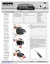
Xerox 5400N - Phaser B/W Laser Printer Technical Instructions (5 pages)
Technical Reference
Brand:
Xerox
| Category:
Printer Accessories
| Size: 0.23 MB
Advertisement
Related Products
Xerox PHASER 5400
Xerox 5400DT - Phaser B/W Laser Printer
Xerox 5400DX - Phaser B/W Laser Printer
Xerox Phaser 5550
Xerox WorkCentre 5632
Xerox WorkCentre 5687
Xerox WorkCentre 5645
Xerox WorkCentre 5655
Xerox 5500DN - Phaser B/W Laser Printer
Xerox 5500N - Phaser B/W Laser Printer
Xerox Categories
Printer
All in One Printer
Copier
Printer Accessories
Scanner
More Xerox Manuals
Login
Sign In
OR
Sign in with Facebook
Sign in with Google
Upload manual
Upload from disk
Upload from URL