Sign In
Upload
Manuals
Brands
Omron Manuals
Conference System
SmartSlice GRT1-Series
Omron SmartSlice GRT1-Series Manuals
Manuals and User Guides for Omron SmartSlice GRT1-Series. We have
4
Omron SmartSlice GRT1-Series manuals available for free PDF download: Operation Manual
OMRON SmartSlice GRT1-Series Operation Manual (365 pages)
Slice I/O Units
Brand:
OMRON
| Category:
Network Hardware
| Size: 8.95 MB
Table of Contents
Table of Contents
7
Precautions
14
General Precautions
15
Intended Audience
15
Safety Precautions
15
Operating Environment Precautions
16
Application Precautions
17
EC Directives
19
Section 1 Available Units and Features
22
Available Units and Features
22
Slice I/O Terminal Introduction
23
Features of the GRT1-Series Slice I/O Units
23
Available Units
28
Communications Units
28
Digital I/O Units
28
Analog I/O Units
28
Counter Units and Positioning Unit
29
System Units
29
Connecting Cable
30
Functions Supported by Slice I/O Units
30
Slice I/O Unit Installation and Power Supply Methods
31
Section 2 Shared Specifications and Functions
32
Shared Specifications and Functions
32
Specifications Shared by the Units
33
General Specifications
33
Slice I/O Unit Specifications
33
LED Indicators
33
Unit Numbers and I/O Allocations
34
Unit Numbers of Slice I/O Units (Automatically Allocated)
34
I/O Allocations in the Slice I/O Terminal's Master Unit
35
Functions Shared by All Units
38
Backup Function
38
Automatic Restore Function
39
Online Replacement Function
40
Unit Conduction Time Monitor
41
Unit Comments
43
I/O Comments
44
Communications Error History Monitor
47
Last Maintenance Date
49
Section 3 Installation and Wiring
50
Installation and Wiring
50
Installation
51
Connecting the Communications Unit and Slice I/O Units
51
Connecting Additional Slice I/O Units
52
Installation on a DIN Track
53
Power Supply Wiring
57
Connecting the Slice I/O Terminal Power Supply
58
Wiring Methods
60
Connecting Turnback Cables
61
Connecting Turnback Units
62
Section 4 Digital I\/O Units
64
Digital I/O Units
64
Overview
65
Specifications Shared by the Units
65
I/O Data
65
Status Area
66
Status Areas of Digital I/O Units
66
I/O Wiring
68
Wiring to the Screwless Clamping Terminal Block
68
Functions of Digital I/O Units
69
I/O Power Supply Monitor
69
Input Filter (Input Units Only)
70
Sensor Power on Delay (Input Units Only)
73
Contact Operation Counter
74
Total on Time Monitor
76
Operation Time Monitor
79
Output Hold/Clear Setting
80
Maintenance Information Window
81
Checking Maintenance Information
81
Digital I/O Units
85
Four-Point DC Input Units: GRT1-ID4 (NPN) and GRT1-ID4-1 (PNP)
85
Four-Point Transistor Output Units: GRT1-OD4 (NPN), GRT1-OD4-1 (PNP), GRT1-OD4G-1 (PNP), GRT1-OD4G-3 (PNP)
88
Eight-Point DC Input Units: GRT1-ID8 (NPN) and GRT1-ID8-1 (PNP)
94
Eight-Point Transistor Output Units: GRT1-OD8 (NPN), GRT1-OD8-1 (PNP), and GRT1-OD8G-1 (PNP)
100
Two-Point Relay Output Unit: GRT1-ROS2
104
Four-Point AC Input Units: GRT1-IA4-1 and GRT1-IA4-2
106
Section 5 Analog I\/O Units
110
Overview of Analog I/O Units
111
Analog I/O Units
111
Comparison with Earlier Models
111
List of Data Processing Functions
113
Data Processing Flowcharts (Analog Input Units)
114
Selecting Data (Analog Input Units)
114
I/O Data
115
Status Areas
116
Maintenance Information Window
118
Checking Maintenance Information
119
Analog Input Units
120
GRT1-AD2 Analog Input Units
120
I/O Data Allocation Methods
127
Functions and Settings
132
Calculating the Conversion Cycle
157
Analog Output Units
158
GRT1-DA2C/GRT1-DA2V Analog Output Units
158
I/O Data and Allocation Methods
165
Functions and Setting Methods
165
Section 6 Temperature Input Units
176
Temperature Input Units
176
Overview of the Temperature Input Units
177
Temperature Input Units
177
Comparison with Previous Models with Platinum Resistance Thermometer Inputs
177
Comparison with Previous Models with Thermocouple Inputs
179
List of Data Processing Functions
180
Data Processing Flowcharts
180
Selecting Data
181
I/O Data
182
Status Areas
183
Maintenance Information Window
185
Checking Maintenance Information
185
Temperature Input Units
188
GRT1-TS2@ Temperature Input Units
188
Temperature Input Unit Display Modes
201
I/O Data Allocation Methods
203
Functions and Settings
209
Section 7 Counter Units and Positioning Unit
246
Overview
247
Counter Units and Positioning Unit
247
List of Data Processing Functions
247
I/O Data
248
Status Areas
248
Maintenance Information Window
250
Checking Maintenance Information
250
GRT1-CT1(-1) Counter Units
256
Specifications
256
Hardware
258
I/O Data Details
261
Functions and Settings
263
GRT1-CP1-L Positioning Unit
273
Specifications
273
Hardware
275
I/O Data Details
279
Functions and Settings
282
Section 8 Other Units
294
Other Units
294
GRT1-TBR Right Turnback Unit
295
GRT1-TBL Left Turnback Unit
295
GRT1-PD2 and GRT1-PD2G I/O Power Feed Units
296
GRT1-PD8(-1) I/O Power Feed Units and GRT1-PC8(-1) I/O Power Connection Units
298
GRT1-END End Unit
300
Section 9 Troubleshooting
302
Troubleshooting
302
Troubleshooting Overview
303
Checking the Slice I/O Terminal's Status
303
LED Indicators
303
LED Indicators and Error Processing
304
Reading the Error History with a Programming Device
308
Checking Maintenance Information
308
Error History
311
Other Errors
312
Troubleshooting by Unit
314
A Explicit Messages
324
B Standard Models
352
C Power Consumption and Weight Tables
355
D I/O Current Consumption Table
356
E Precautions When Connecting Two-Wire DC Sensors
358
Index
360
Revision History
364
Advertisement
Omron SmartSlice GRT1-Series Operation Manual (366 pages)
Brand:
Omron
| Category:
I/O Systems
| Size: 12.76 MB
Table of Contents
Precautions
13
Table of Contents
13
Intended Audience
14
General Precautions
14
Safety Precautions
14
Operating Environment Precautions
15
Application Precautions
16
EC Directives
18
Section 1 Available Units and Features
21
Features of the GRT1-Series Slice I/O Units
22
Slice I/O Terminal Introduction
22
Analog I/O Units
27
Available Units
27
Communications Units
27
Digital I/O Units
27
Counter Units and Positioning Unit
28
System Units
28
Connecting Cable
29
Functions Supported by Slice I/O Units
29
Slice I/O Unit Installation and Power Supply Methods
30
Section 2 Shared Specifications and Functions
31
General Specifications
32
LED Indicators
32
Slice I/O Unit Specifications
32
Specifications Shared by the Units
32
Unit Numbers and I/O Allocations
33
Unit Numbers of Slice I/O Units (Automatically Allocated)
33
I/O Allocations in the Slice I/O Terminal's Master Unit
34
Backup Function
37
Functions Shared by All Units
37
Automatic Restore Function
38
Online Replacement Function
39
Unit Conduction Time Monitor
40
Unit Comments
43
I/O Comments
44
Communications Error History Monitor
46
Last Maintenance Date
48
Section 3 Installation and Wiring
49
Connecting the Communications Unit and Slice I/O Units
50
Installation
50
Connecting Additional Slice I/O Units
51
Installation on a DIN Track
52
Power Supply Wiring
56
Connecting the Slice I/O Terminal Power Supply
57
Wiring Methods
59
Connecting Turnback Cables
60
Connecting Turnback Units
61
Section 4 Digital I\/O Units
63
I/O Data
64
Overview
64
Specifications Shared by the Units
64
Status Area
65
Status Areas of Digital I/O Units
65
I/O Wiring
67
Wiring to the Screwless Clamping Terminal Block
67
Functions of Digital I/O Units
68
I/O Power Supply Monitor
68
Input Filter (Input Units Only)
69
Sensor Power on Delay (Input Units Only)
72
Contact Operation Counter
73
Total on Time Monitor
75
Operation Time Monitor
78
Output Hold/Clear Setting
79
Checking Maintenance Information
80
Maintenance Information Window
80
Digital I/O Units
84
Four-Point DC Input Units: GRT1-ID4 (NPN) and GRT1-ID4-1 (PNP)
84
Four-Point Transistor Output Units: GRT1-OD4 (NPN), GRT1-OD4-1 (PNP), GRT1-OD4G-1 (PNP), GRT1-OD4G-3 (PNP)
87
Eight-Point DC Input Units: GRT1-ID8 (NPN) and GRT1-ID8-1 (PNP)
93
Eight-Point Transistor Output Units: GRT1-OD8 (NPN), GRT1-OD8-1 (PNP), and GRT1-OD8G-1 (PNP)
99
Two-Point Relay Output Unit: GRT1-ROS2
104
Four-Point AC Input Units: GRT1-IA4-1 and GRT1-IA4-2
106
Section 5 Analog I\/O Units
109
Analog I/O Units
110
Comparison with Earlier Models
110
Overview of Analog I/O Units
110
List of Data Processing Functions
112
Data Processing Flowcharts (Analog Input Units)
113
Selecting Data (Analog Input Units)
113
I/O Data
114
Status Areas
115
Maintenance Information Window
117
Checking Maintenance Information
118
Analog Input Units
119
GRT1-AD2 Analog Input Units
119
I/O Data Allocation Methods
126
Functions and Settings
131
Calculating the Conversion Cycle
156
Analog Output Units
157
GRT1-DA2C/GRT1-DA2V Analog Output Units
157
Functions and Setting Methods
164
I/O Data and Allocation Methods
164
Section 6 Temperature Input Units
175
Comparison with Previous Models with Platinum Resistance Thermometer Inputs
176
Overview of the Temperature Input Units
176
Temperature Input Units
176
Comparison with Previous Models with Thermocouple Inputs
178
Data Processing Flowcharts
179
List of Data Processing Functions
179
Selecting Data
180
I/O Data
181
Status Areas
182
Checking Maintenance Information
184
Maintenance Information Window
184
GRT1-TS2@ Temperature Input Units
187
Temperature Input Units
187
Temperature Input Unit Display Modes
200
I/O Data Allocation Methods
202
Functions and Settings
208
Section 7 Counter Units and Positioning Unit
245
Counter Units and Positioning Unit
246
List of Data Processing Functions
246
Overview
246
I/O Data
247
Status Areas
247
Checking Maintenance Information
249
Maintenance Information Window
249
GRT1-CT1(-1) Counter Units
255
Specifications
255
Hardware
257
I/O Data Details
260
Functions and Settings
262
GRT1-CP1-L Positioning Unit
272
Specifications
272
Hardware
274
I/O Data Details
278
Functions and Settings
281
Section 8 Other Units
293
GRT1-TBL Left Turnback Unit
294
GRT1-TBR Right Turnback Unit
294
GRT1-PD2 and GRT1-PD2G I/O Power Feed Units
295
GRT1-PD8(-1) I/O Power Feed Units and GRT1-PC8(-1) I/O Power Connection Units
297
GRT1-END End Unit
299
Section 9 Troubleshooting
301
Checking the Slice I/O Terminal's Status
302
LED Indicators
302
Troubleshooting Overview
302
LED Indicators and Error Processing
303
Checking Maintenance Information
307
Reading the Error History with a Programming Device
307
Error History
310
Other Errors
311
Troubleshooting by Unit
313
Omron SmartSlice GRT1-Series Operation Manual (243 pages)
Slice I/O Units
Brand:
Omron
| Category:
I/O Systems
| Size: 7.68 MB
Table of Contents
Table of Contents
6
Precautions
14
Intended Audience
15
General Precautions
15
Safety Precautions
15
Operating Environment Precautions
16
Application Precautions
17
EC Directives
18
Section 1
20
Available Units and Features
20
Slice I/O Terminal Introduction
21
Features of the GRT1-Series Slice I/O Units
21
Available Units
25
Section 2
28
Shared Specifications and Functions
28
Specifications Shared by the Units
29
Unit Numbers and I/O Allocations
30
Functions Shared by All Units
33
Section 3 Installation and Wiring
44
Section 3
44
Installation and Wiring
44
Installation
45
Connecting the Communications Unit and Slice I/O Unit
45
Connecting Additional Slice I/O Units
46
Installation on a DIN Track
47
Power Supply Wiring
50
Connecting the Slice I/O Terminal Power Supply
50
Wiring Methods
51
Connecting Turnback Cables
53
Connecting Turnback Units
53
Section 4 General-Purpose Slice I\/O Units
56
Section 4
56
General-Purpose Slice I/O Units
56
Specifications Shared by the Units
57
Status Area
58
Status Areas of General-Purpose Slice I/O Units
58
I/O Wiring
60
Wiring to the Screwless Clamping Terminal Block
60
Functions of General-Purpose Slice I/O Units
61
I/O Power Supply Monitor
61
Input Filter (Input Units Only)
62
Sensor Power on Delay (Input Units Only)
64
Contact Operation Counter
65
Total on Time Monitor
67
Operation Time Monitor
70
Output Hold/Clear Setting
71
Maintenance Information Window
72
Checking Maintenance Information
72
General-Purpose Slice I/O Units
76
Input Units with Four Transistor Inputs: GRT1-ID4 (NPN) and GRT1-ID4-1 (PNP)
76
Output Units with Four Transistor Outputs: GRT1-OD4 (NPN) and GRT1-OD4-1 (PNP)
79
Relay Output Unit with Two Relay Outputs: GRT1-ROS2
82
Section 5 Analog Units
86
Section 5
86
Analog Units
86
Overview of Analog Units
87
Analog Units
87
Comparison with Earlier Models
87
List of Data Processing Functions
89
Data Processing Flowcharts (Analog Input Units)
90
Selecting Data (Analog Input Units)
90
I/O Data
91
Status Areas
92
Maintenance Information Window
94
Checking Maintenance Information
95
Analog Input Units
96
GRT1-AD2 Analog Input Units
96
I/O Data Allocation Methods
103
Functions and Settings
108
Calculating the Conversion Cycle
133
Analog Output Units
134
GRT1-DA2C/GRT1-DA2V Analog Output Units
134
I/O Data and Allocation Methods
140
Functions and Setting Methods
140
Section 6 Counter Units and Positioning Unit
152
Overview
153
Counter Units and Positioning Unit
153
List of Data Processing Functions
153
I/O Data
154
Status Areas
154
Maintenance Information Window
156
Checking Maintenance Information
156
GRT1-CT1(-1) Counter Units
162
Specifications
162
Hardware
164
I/O Data Details
167
Functions and Settings
169
GRT1-CP1-L Positioning Unit
179
Specifications
179
Hardware
181
I/O Data Details
185
Functions and Settings
188
Section 7 Other Units
200
GRT1-TBL Left Turnback Unit
201
GRT1-TBR Right Turnback Unit
201
GRT1-PD2 I/O Power Supply Unit
202
GRT1-END End Unit
204
Section 8 Troubleshooting
206
Troubleshooting Overview
207
Checking the Slice I/O Terminal's Status
207
LED Indicators
207
LED Indicators and Error Processing
208
Reading the Error History with a Programming Device
210
Checking Maintenance Information
210
Error History
212
Other Errors
213
Advertisement
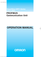
OMRON SmartSlice GRT1-Series Operation Manual (111 pages)
PROFIBUS Communication Unit
Brand:
OMRON
| Category:
Conference System
| Size: 4.16 MB
Table of Contents
Table of Contents
6
About this Manual
8
Precautions
14
General Precautions
15
Intended Audience
15
Safety Precautions
15
Operating Environment Precautions
16
Application Precautions
17
Conformance to EC Directives
18
Applicable Directives
18
Concepts
18
Conformance to EC Directives
19
Section 1 Features and Specifications
20
Features and Specifications
20
Overview of GRT1-Series Smartslice I/O Units
21
GRT1-PRT PROFIBUS Communication Unit
22
Features
22
System Configuration
23
Specifications
24
GRT1-PRT Configuration
26
Basic Operating Procedure
28
Overview
28
Section 2
28
Preparations for Use
29
Section 2 Installation and Wiring
30
Installation and Wiring
30
Unit Components
31
Nomenclature
31
LED Indicators
31
Switch Settings
32
Power Supply Connector
34
PROFIBUS Connector
34
Installing the GRT1-PRT Unit
35
Handling Precautions
35
Installation on a DIN Rail
35
Connecting the PROFIBUS Unit and Smartslice I/O Units
37
Connecting Additional Smartslice I/O Units
37
Wiring the GRT1-PRT
39
Connecting the Smartslice I/O System Power Supply
39
Wiring Methods
40
Connecting the Turnback Units
42
Setting up a PROFIBUS Network
43
Network Structure
43
Bus Termination
45
PROFIBUS Cable Connector
46
Shielding Precautions
46
Installation of Configuration Software
47
Installation Requirements
47
Installation Procedure
47
GRT1-PRT GSD File
48
Section 3 Setup and Operation
50
Setup and Operation
50
Station Address Settings and I/O Allocation
51
Setting the PROFIBUS Station Address
51
Smartslice I/O Unit Number Allocation
51
Smartslice I/O Allocation to the GRT1-PRT Unit
52
Unit Functions
55
Backup Function
57
Automatic Restore Function
57
Online Replacement Function
59
I/O Communication Error History Monitor
60
Setup the GRT1-PRT Configuration
61
Defining the PROFIBUS Network
61
Setup Using the DTM
62
Setup Using the GSD File
67
Mapping I/O Data
70
Operating the Network
71
Monitoring the GRT1-PRT
71
Monitoring the Smartslice I/O System
73
Remote Communication Characteristics
74
I/O Communication Characteristics
74
Message Communication Characteristics
77
Section 4 Troubleshooting and Maintenance
78
Troubleshooting and Maintenance
78
Overview
79
Troubleshooting Using the LED Indicators
79
Power Supply Errors
80
Unit System Errors
81
Smartslice I/O System Errors
81
PROFIBUS Errors
82
Other Errors
83
Troubleshooting Smartslice I/O Communication
83
Troubleshooting Profibus Communication
84
Smartslice I/O Unit Error History
86
Maintenance
88
Cleaning
88
Inspection
88
Replacing the Unit
89
Replacement Precautions
89
Setting the Unit after Replacement
89
PROFIBUS Technology
90
Slave Diagnostics Message
96
Explicit Messages
100
Index
106
Revision History
110
Advertisement
Related Products
Omron SmartSlice GRT1-CRT
OMRON SMARTSLICE
Omron SMARTSLICE GRT1-PNT
OMRON SMARTSTEP 2 SERIES
OMRON SMARTSTEP SERVO DRIVE
OMRON SMARTSTEP2
Omron SMARTSTEP A Series
Omron SMARTSTEP Junior
Omron Smart Process Control CJ-Series
Omron Smart Sensor ZFX-C
Omron Categories
Blood Pressure Monitor
Controller
Accessories
Switch
Inverter
More Omron Manuals
Login
Sign In
OR
Sign in with Facebook
Sign in with Google
Upload manual
Upload from disk
Upload from URL