Table of Contents
Advertisement
Quick Links
Advertisement
Chapters
Table of Contents
Troubleshooting

Related Manuals for Omron GRT1 - 11-2007


Summary of Contents for Omron GRT1 - 11-2007
- Page 1 Cat. No. W455-E1-06 SmartSlice GRT1 Series Slice I/O Units OPERATION MANUAL...
- Page 2 SmartSlice GRT1 Series Slice I/O Units Operation Manual Revised November 2007...
- Page 4 OMRON, 2005 All rights reserved. No part of this publication may be reproduced, stored in a retrieval system, or transmitted, in any form, or by any means, mechanical, electronic, photocopying, recording, or otherwise, without the prior written permission of OMRON.
- Page 6 SECTION 4 Digital I/O Units ........
-
Page 7: Table Of Contents
Other Units ........ - Page 8 This manual describes the installation and operation of the Slice I/O Units and includes the sections described below. Please read this manual carefully and be sure you understand the information pro- vided before attempting to install or operate Slice I/O Units. Be sure to read the precautions pro- vided in the following section.
- Page 9 DC sensors. !WARNING Failure to read and understand the information provided in this manual may result in per- sonal injury or death, damage to the product, or product failure. Please read each section in its entirety and be sure you understand the information provided in the section and related sections before attempting any of the procedures or operations given.
- Page 10 WHETHER SUCH CLAIM IS BASED ON CONTRACT, WARRANTY, NEGLIGENCE, OR STRICT LIABILITY. In no event shall the responsibility of OMRON for any act exceed the individual price of the product on which liability is asserted. IN NO EVENT SHALL OMRON BE RESPONSIBLE FOR WARRANTY, REPAIR, OR OTHER CLAIMS...
- Page 11 The following are some examples of applications for which particular attention must be given. This is not intended to be an exhaustive list of all possible uses of the products, nor is it intended to imply that the uses listed may be suitable for the products: •...
- Page 12 PERFORMANCE DATA Performance data given in this manual is provided as a guide for the user in determining suitability and does not constitute a warranty. It may represent the result of OMRON's test conditions, and the users must correlate it to actual application requirements.
- Page 14 Application Precautions ........
-
Page 15: Intended Audience
!WARNING It is extremely important that a PLC and all PLC Units be used for the speci- fied purpose and under the specified conditions, especially in applications that can directly or indirectly affect human life. You must consult with your OMRON representative before applying a PLC system to the above mentioned applica- tions. -
Page 16: Operating Environment Precautions
• The PLC outputs may remain ON or OFF due to deposits on or burning of the output relays, or destruction of the output transistors. As a counter- measure for such problems, external safety measures must be provided to ensure safety in the system. -
Page 17: Application Precautions
• Locations subject to possible exposure to radioactivity. • Locations close to power supplies. !Caution The operating environment of the PLC System can have a large effect on the longevity and reliability of the system. Improper operating environments can lead to malfunction, failure, and other unforeseeable problems with the PLC System. - Page 18 • Be sure to press terminals until they are fully seated. • Mount Units only after checking terminal blocks completely. • Before mounting a wired terminal block to the main block, be sure that the terminal block-main block combination is correct.
-
Page 19: Ec Directives
EMC Directive OMRON devices that comply with EC Directives also conform to the related EMC standards, so that they can more easily be built in to other devices or the overall machine. The actual products have been checked for conformity to EMC standards. - Page 20 33 mm 13 mm 29 mm 2. Wire the control panel with as thick and short cables as possible and ground to 100 Ω min. 3. Keep DeviceNet communications cables as short as possible and ground to 100 Ω min.
- Page 21 EC Directives xxii...
-
Page 22: Available Units And Features
This section describes the features of GRT1-series Slice I/O Units and lists the available Units. Slice I/O Terminal Introduction ........ -
Page 23: Slice I/O Terminal Introduction
The GRT1-series Slice I/O Units have the following features. Features Shared by all Units Small I/O Increments The GRT1-series Slice I/O Units have just a few I/O points (2 to 4 points) per Unit, so the application can be flexibly constructed to match the space and capacity requirements. - Page 24 This function records the total time that the Slice I/O Unit's internal circuit (Power ON Time) Monitor power has been ON. A warning level can be set in the Unit and a warning flag will be turned ON when the set warning time is exceeded. The Power ON Time can be read with an explicit message command or from the Configura- tor.
- Page 25 Configurator or explicit messages. A warning set value can be set in the Unit to monitor the total ON time, and turn ON a warning flag in the Sta- tus Area when the set value is reached.
- Page 26 Slice I/O Terminal Introduction The status can be checked at the Master using the Off-wire Detection Flag. This function is valid only for the input ranges 4 to 20 mA and 1 to 5 V. User Adjustment Input or output values can be adjusted to compensate for errors in the input or output voltage or current resulting from the characteristics or connection methods of the I/O device.
- Page 27 The temperature differences between input channels 0 and 1 can be calcu- Channels lated and compared to a set value. The host will be notified with a flag when the temperature difference exceeds a set value. Counter Unit and Positioning Unit Features Counter Each Unit provides one high-speed counter with a 32-bit resolution.
-
Page 28: Available Units
Available Units Section 1-2 Available Units The following tables list the available GRT1-series Units, categorized by type. 1-2-1 Communications Units Type I/O points Model number Description DeviceNet Communications GRT1-DRT Interface Unit that con- Unit nects the DeviceNet Unit with the Slice I/O... -
Page 29: Counter Units And Positioning Unit
Model number Description Counter • A and B counter inputs GRT1-CT1 1 counter Units • One input settable to Z counter Max. frequency: input or digital input 60 kHz (depend- ing on counter • 1 digital output (NPN) input mode) •... -
Page 30: Connecting Cable
I/O points Model number Description Turnback Cable for GCN2-100 This is a special turnback cable. Slice I/O Units (1 m) Up to 2 Turnback Cables (2 m total) can be connected for one Communications Unit. 1-2-7 Functions Supported by Slice I/O Units Function... -
Page 31: Slice I/O Unit Installation And Power Supply Methods
Section 1-2 Available Units 1-2-8 Slice I/O Unit Installation and Power Supply Methods The following installation and power supply methods apply to all GRT1-series Units. I/O Unit connection Unit I/O connection Unit power supply to I/O power supply installation base block... -
Page 32: Shared Specifications And Functions
Backup Function........ -
Page 33: Specifications Shared By The Units
The following table shows the meaning of the Unit’s TS and I/O indicators, which are common to all of the Slice I/O Units. The ERR indicators show errors specific to the Unit, such as I/O errors. Any numbers that immediately follow “ERR” indicate the channel number, e.g. -
Page 34: Unit Numbers And I/O Allocations
Section 2-2 Unit Numbers and I/O Allocations The TS indicator shows the status of the Slice I/O Unit itself and the I/O indi- cators show the status of the connected devices. Name Color Status Meaning Green Normal status Normal Unit status... -
Page 35: I/O Allocations In The Slice I/O Terminal's Master Unit
Communications Unit and the Unit (such as a DeviceNet Unit) connected to the CPU Unit. The Communications Unit’s Programming Device (such as a Configurator) can be used to freely select the kind of data allocated. Refer to the Communi- cations Unit’s operation manual for details. CPU Unit... - Page 36 Section 2-2 Unit Numbers and I/O Allocations I/O Allocation I/O data is allocated to the I/O Units in the order that they are connected to the Example Communications Unit, regardless of the I/O Units’ models. Unless special allocation data settings are selected with the Communications Unit’s Pro- gramming Device, data is allocated from the first word starting with the Com- munications Unit’s Status Flags and then the leftmost I/O Unit’s data.
- Page 37 Such an area cannot be used for any other purpose. If there is more than 1 byte that do not create a gap in any other area, such as in word 4 in example 2, then they can be used for other purposes.
-
Page 38: Functions Shared By All Units
Downloads all of the I/O Units' unit information and parameter data. Backup Procedure when using a DeviceNet Communications Unit 1,2,3... 1. Verify that the power is ON, DIP switch pin 1 (REGS) is ON, and all of the Slice I/O Units are participating in I/O communications. -
Page 39: Automatic Restore Function
Section 2-3 Functions Shared by all Units 2. Turn DIP switch pin 4 (BACK) ON, then OFF, and then ON again within 3 s to start the back up. 3. While the data is being backed up, the DeviceNet Communications Unit’s TS indicator will flash green every 0.5 s. -
Page 40: Online Replacement Function
1,2,3... 1. Turn OFF the I/O power supply of the I/O Unit being replaced. 2. Release the hook on the front of the I/O Unit that you want to replace and remove the terminal block. The wiring can remain connected. -
Page 41: Unit Conduction Time Monitor
In addition, if external power is supplied to the terminal block for a Unit such as a Relay Output Unit or AC Input Unit, turn OFF that power sup- ply before replacing the Unit. Not turning OFF these power supplies may result in false output signals, false input signals, or electrical shock. - Page 42 Internal circuit power Note The Unit conduction time monitor (Power ON time monitor) calculates the total time that Network power supply is ON. The total time is not calculated when the power is OFF. Setting with a This example shows how to use the DeviceNet Configurator (version 2.43 or Programming Device higher) to set the monitor value for the Unit Conduction Time.
-
Page 43: Unit Comments
2-3-5 Unit Comments Function Overview The user can assign and record a name or comment for every Unit (up to 32 characters). The network Programming Device can be used to read and write these Unit names (comments). Set a Unit name with the Programming Device. -
Page 44: I/O Comments
I/O Comments Function Overview The user can assign a name for each of the Unit's I/O contacts (up to 32 char- acters) and record it in the Unit. The connected device can be checked for each I/O contact, allowing faulty devices to be identified during remote main- tenance. - Page 45 Functions Shared by all Units Section 2-3 Set a device comment with the Programming Device. Connected device comment Slice I/O Unit Recorded in Unit Connected device What is this connected device used for?
- Page 46 2. Select the desired Slice I/O Unit from the list on the I/O Module Tab Page and click the Edit Button. 3. Select the IN Tab or OUT Tab. (In this case, the IN Tab has been selected.) 4. Select the connected device that requires a comment and double-click the I/O Comment Column to display the following window.
-
Page 47: Communications Error History Monitor
Function Overview Information on communications error (communications error code, communi- cations power voltage when the error occurred) for the last four communica- tions errors can be recorded in the Unit. The network Programming Device can be used to read that communications error history. - Page 48 Functions Shared by all Units Section 2-3 2. Select the desired Slice I/O Unit from the list on the I/O Module Tab Page and click the View Button. 3. Select the Error History Tab in the Maintenance Information Window. The communications error history for the last four errors will be displayed,...
-
Page 49: Last Maintenance Date
Slice I/O Terminal’s icon or right-click the icon and select Parameters - Edit to display the Edit Device Parameters Window. 2. Select the desired Slice I/O Unit from the list on the I/O Module Tab Page and click the Edit Button. -
Page 50: Installation And Wiring
Connecting Turnback Cables ........ -
Page 51: Installation
Section 3-1 Installation Installation The Slice I/O Terminal is installed and set up as a network Slave. The Com- munications Unit’s communications connector connects to the Master Unit through a communications cable. Up to 64 Slice I/O Units can be connected to one Communications Unit. -
Page 52: Connecting Additional Slice I/O Units
Connecting Additional Slice I/O Units Connect additional Slice I/O Units by aligning the sides of the Units and slid- ing in the next Unit from the front. Up to 64 Slice I/O Units can be connected to one Communications Unit. -
Page 53: Installation On A Din Track
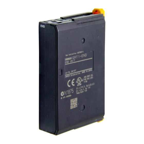
GRT1-END End Unit Note When connecting Units, always align the guide tracks on the top and bottom of the Units and be sure that they join properly as you slide the Unit toward the DIN Track. 3-1-3 Installation on a DIN Track DIN Track Installation Mount the Communications Unit and Slice I/O Units on a DIN Track. - Page 54 In that case, release the Mounting Hook locks, mount the Unit on the DIN Track again, and lock the Mounting Hooks. Slice I/O Unit The Slice I/O Units are made up of 3 blocks. Each block can be removed for Structure replacement.
- Page 55 Removing a Unit Use a standard screwdriver to release the DIN Track Mounting Hooks at the top and bottom of the Unit and pull the Unit straight away from the DIN Track.
- Page 56 Removing an Entire Unit Including the Base Block 1,2,3... 1. Remove the main block of the Unit on the right side of the Slice I/O Unit actually being replaced. 2. Release the Mounting Hook locks of the Unit being replaced. (The hooks attach the Unit to the top and bottom of the DIN Track.)
-
Page 57: Power Supply Wiring
Terminal. First hook the bottom of the End Plate on the bottom edge of the DIN Track (1), attach the top of the End Plate, and pull the End Plate down onto the top edge of the DIN Track (2). -
Page 58: Connecting The Slice I/O Terminal Power Supply
(1) There is a small amount of electrical resistance in the connections be- tween the Slice I/O Units. This can result in a voltage drop of up to 2 V when 64 Slice I/O Units are connected at 4 A. Consider this voltage drop when designing the system. - Page 59 I/O Power Connection Unit Communications Unit (OUT) (OUT) (OUT) (IN) (IN) (OUT) Connector Do not exceed 80 W power consumption in one block (excluding the I/O power supply). power power Power is not supplied through supply supply the Turnback Cable.
-
Page 60: Wiring Methods
The power supply for external I/O devices is supplied through the Communi- External I/O cations Unit’s screwless clamping power supply terminals. If pin terminals are used on the wire ends, the pin terminals can just be inserted to wire the power. Release button... -
Page 61: Connecting Turnback Cables
(0.5 to 1.25 mm Solid wire Pin terminal Strip Length Strip between 7 and 10 mm of insulation at the ends of the wires (stranded or solid wire). Strip 7 to 10 mm. Pin Terminal Length Use pin terminals with a pin (conductor) length of 8 to 10 mm. -
Page 62: Connecting Turnback Units
Section 3-3 3-3-1 Connecting Turnback Units Connect Turnback Units with Turnback Cable, as shown in the following dia- gram. A single Communications Unit can be expanded with up to two sets of Right/Left Turnback Units. GRT1-TBR Turnback Unit GCN2-100 Turnback Cable... - Page 63 Connecting Turnback Cables Section 3-3...
-
Page 64: Digital I/O Units
Functions of Digital I/O Units ........ -
Page 65: Overview
4-6-5 Two-point Relay Output Unit: GRT1-ROS2. 4-1-2 I/O Data The following table lists the I/O data allocated to each Digital I/O Unit. Refer also to 2-2-2 I/O Allocations in the Slice I/O Terminal’s Master Unit. Unit name... -
Page 66: Status Area
ON and OFF based on the threshold/monitor values set for the function in that Unit. A flag in the Communications Unit will be turned ON only when the corresponding flag has been turned ON in one of those status areas. - Page 67 The Slice I/O Unit’s alarm status area contains the following 16 bits. The Alarm Status Area provides notification of serious errors detected in the Unit. When any of these flags goes ON, bit 3 of the Communications Unit’s Status Flags is turned ON and that information is transmitted to the Master.
-
Page 68: I/O Wiring
4-3-1 Wiring to the Screwless Clamping Terminal Block All of the GRT1-series Slice I/O Units can be wired with screwless clamp ter- minal blocks, which do not require screws to be tightened. When connecting a sensor or an external device, always crimp pin terminals to the cable of the sensor or device. -
Page 69: Functions Of Digital I/O Units
Crimp the pin terminals on the sides that align with wide sides of the in- sulating cover, as shown in the following figure. -
Page 70: Input Filter (Input Units Only)
When input data changes to ON, the input data is read four times for the period of the set interval (1/4 of the ON response time). If all values are ON, the input is turned ON. The ON timing is delayed according to the length of... - Page 71 Section 4-4 Functions of Digital I/O Units The input filter can also be used to perform an ON delay operation (a delay for the ON response time is created when the input filter is enabled). All values are ON Not all values are...
- Page 72 Slice I/O Terminal’s icon or right-click the icon and select Parameters - Edit to display the Edit Device Parameters Window. 2. Select the desired Slice I/O Unit from the list on the I/O Module Tab Page and click the Edit Button to display the Edit Unit Parameters Window.
-
Page 73: Sensor Power On Delay (Input Units Only)
Slice I/O Terminal’s icon or right-click the icon and select Parameters - Edit to display the Edit Device Parameters Window. 2. Select the desired Slice I/O Unit from the list on the I/O Module Tab Page and click the Edit Button to display the Edit Unit Parameters Window. -
Page 74: Contact Operation Counter
OFF to ON (maximum resolution 50 Hz) and record the total value calculated in the Unit. The monitor value can be set in the Unit, and when the set number of opera- tions is reached, the Connected Device Maintenance Flag in the Status Area will be turned ON. - Page 75 Slice I/O Terminal’s icon or right-click the icon and select Parameters - Edit to display the Edit Device Parameters Window. 2. Select the desired Slice I/O Unit from the list on the I/O Module Tab Page and click the Edit Button to display the Edit Unit Parameters Window.
-
Page 76: Total On Time Monitor
■ Measurement for ON Time of 0.5 s: In Figure 1, the actual ON time is 0.5 s × 3 = 1.5 s. The measurement will be taken once during this ON time, so the total ON time will be measured as 1 s. - Page 77 Functions of Digital I/O Units In Figure 2, the actual ON time is 0.5 s × 3 = 1.5 s. The reading will be taken twice during this ON time, so the total ON time will be measured as 2 s.
- Page 78 3. Select the desired device and double-click the I/O Comment Column to display the following window. Select the Time Option in the Detection Mode Area, enter a monitor value in the Value Field, and then click the OK But- ton.
-
Page 79: Operation Time Monitor
A monitor value can be set in the Unit to monitor the operating time, and turn ON a warning flag in the Status Area when the set value is reached. A monitor value can be set in the Unit, and when the operating time exceeds the monitor value, the Operation Time Monitor Flag in the Status Area is turned ON. -
Page 80: Output Hold/Clear Setting
Slice I/O Terminal’s icon or right-click the icon and select Parameters - Edit to display the Edit Device Parameters Window. 2. Select the desired Slice I/O Unit from the list on the I/O Module Tab Page and click the Edit Button to display the Edit Unit Parameters Window. -
Page 81: Maintenance Information Window
From the Programming Device’s Main Window, click the right mouse button and select Maintenance Information. (From the Maintenance Mode Window, double-click the icon of the desired Unit.) Click the I/O Module Tab, select the desired Unit, and click the View Button to display the Unit’s Maintenance Information Window. - Page 82 If this function is used, the previous value will be retained when the power supply is turned OFF and ON again. Status Check Boxes for Status Flags The flags shown in the following table will be turned ON when the correspond- ing error occurs. Item...
- Page 83 OUT Tab Page Output terminals are listed in numerical order. Item Description Comment Displays up to 32 characters of text set as the output comment for each output. Maintenance Displays the maintenance counter for each output. If the main- Counter tenance counter exceeds the threshold value, a warning icon will be displayed on the left side of the output’s No.
- Page 84 Section 4-5 Maintenance Information Window Item Description Comment Displays up to 32 characters of text set as the input comment for each input. Maintenance Displays the maintenance counter for each input. If the mainte- Counter nance counter exceeds the threshold value, a warning icon will be displayed on the left side of the input’s No.
-
Page 85: Digital I/O Units
Description Content Displays the contents of the communications errors that have occurred. Unit Conduction Displays the total time that the network power supply had been Time ON when the error occurred. Digital I/O Units 4-6-1 Four-point DC Input Units: GRT1-ID4 (NPN) and GRT1-ID4-1 (PNP) - Page 86 Section 4-6 Digital I/O Units Component Names and Functions (Same for GRT1-ID4 and GRT1-ID4-1) LED indicators Indicate the Unit's status. Test pin Release button Terminal insertion hole Terminal Block Internal Circuits GRT1-ID4 (NPN) Terminal block Base block Main block I/O LED...
- Page 87 Black (white) Brown (white) Blue (black) Brown (red) Blue (black) 2-wire sensor (such as a limit switch) 3-wire sensor with NPN output (photoelectric or proximity sensor) Note Wire colors in parentheses are the previous JIS colors for photoelectric and proximity sensors.
-
Page 88: Four-Point Transistor Output Units: Grt1-Od4 (Npn), Grt1-Od4-1 (Pnp), Grt1-Od4G-1 (Pnp), Grt1-Od4G-3 (Pnp)
Number of circuits 4 outputs with one common 4 points, common V/G I/O power supply 24 V I/O power supply voltage supplied via the slice I/O bus 24 V I/O power supply voltage supplied via the unit I/O termi- nal connector. - Page 89 2 points × 2 A + 2 points × 0.7 A 4 points × 1.5 A 50 °C 1 points × 2 A + 1 points × 1.4 A + 2 points × 0.5 A 6.5 A 4 points × 1.25 A 55 °C...
- Page 90 GRT1-OD4G-3 GRT1-OD4 GRT1-OD4-1 GRT1-OD4G-1 PWR Indicator The PWR indicator shows the status of the power supply on the GRT1-OD4G- 3 only. Green I/O power and Unit power are being supplied. Not lit I/O power or Unit power is not being supplied.
- Page 91 Section 4-6 Digital I/O Units GRT1-OD4-1 (PNP) Main block Terminal block Base block I/O LED Internal circuits Voltage step-down Internal circuits GRT1-OD4G-1 (PNP) Main block Terminal block Base block Short- I/O LED circuit detection Internal circuits Voltage step-down Internal circuits...
- Page 92 Digital I/O Units Section 4-6 GRT1-OD4G-3 (PNP) Terminal Base block Main block block Short- I/O LED circuit detection Internal circuits Voltage step-down V (2) Internal circuits G (2) Wiring GRT1-OD4 (NPN) Solenoid, valve, etc. GRT1-OD4-1 (PNP) Solenoid, valve, etc.
- Page 93 Digital I/O Units Section 4-6 GRT1-OD4G-1 (PNP) Solenoid, valve, etc. 3-wire actuator GRT1-OD4G-3 (PNP) Solenoid, valve , etc. 24 VDC 3-wire actuator Dimensions (Same for GRT1-OD4, GRT1-OD4-1, GRT1-OD4G-1, and GRT1-OD4G-3) (88.5) 14.1 74.4 (74.4) OMRON...
-
Page 94: Eight-Point Dc Input Units: Grt1-Id8 (Npn) And Grt1-Id8-1 (Pnp)
ON delay time 1.5 ms max. OFF delay time 1.5 ms max. Number of circuits 8 inputs with one common Component Names and Functions (Same for GRT1-ID8 and GRT1-ID8-1) LED indicators Indicate the Unit's status. Test pin Release button Terminal insertion hole... - Page 95 Digital I/O Units Section 4-6 Internal Circuits GRT1-ID8 (NPN) Terminal block Base block Main block I/O LED Internal circuits Internal circuits 4 × G GRT1-ID8-1 (PNP) Base block Terminal block Main block I/O LED Internal circuits 4 × V Internal circuits...
- Page 96 Blue (black) Blue (black) If the Unit connected on the left needs to be isolated, wire using the GRT1- PD8 I/O Power Feed Unit. When using the GRT1-PD8 I/O Power Feed Unit, however, a maximum of seven sensors can be connected, as shown in the fol- lowing figure.
- Page 97 Section 4-6 Digital I/O Units When connecting 2-wire sensors, wire using the GRT1-PC8-1 I/O Power Con- nection Unit as shown in the following figure. A single I/O Power Connection Unit can be connected to up to two GRT1-ID8 Units. 2-wire sensors...
- Page 98 Digital I/O Units Section 4-6 If the Unit connected on the left needs to be isolated, wire using the GRT1- PD8-1 I/O Power Feed Unit. When using the GRT1-PD8-1 I/O Power Feed Unit, however, a maximum of seven sensors can be connected, as shown in the following figure.
- Page 99 Section 4-6 Digital I/O Units Dimensions (Same for GRT1-ID8 and GRT1-ID8-1) (88.5) 14.1 74.4 (74.4) OMRON...
-
Page 100: Eight-Point Transistor Output Units: Grt1-Od8 (Npn), Grt1-Od8-1 (Pnp), And Grt1-Od8G-1 (Pnp)
1.5 ms max. Number of circuits 8 outputs with one common Note With the GRT1-OD8G-1, even if a short-circuit occurs on one output, the other seven outputs will operate normally. Component Names and Functions (Same for GRT1-OD8, GRT1-OD8-1, and GRT1-OD8G-1) LED indicators Indicate the Unit's status. - Page 101 Section 4-6 Digital I/O Units Internal Circuits GRT1-OD8 (NPN) Main block Terminal block Base block I/O LED Internal circuits Voltage step-down 4 × V Internal circuits GRT1-OD8-1 (PNP) Main block Terminal block Base block I/O LED Internal circuits Voltage step-down Internal circuits 4 ×...
- Page 102 Section 4-6 Digital I/O Units Wiring GRT1-OD8 (NPN) When using a GRT1-PC8 I/O Power Connection Unit, wire according to the following figure. Up to two GRT1-0D8 Units can be wired with a single I/O Power Connection Unit. GRT1-OD8 GRT1-PC8 GRT1-OD8 Solenoids, valves, etc.
- Page 103 Section 4-6 Digital I/O Units Dimensions (Same for GRT1-OD8, GRT1-OD8-1, and GRT1-OD8G-1) (88.5) 14.1 74.4 (74.4) OMRON...
-
Page 104: Two-Point Relay Output Unit: Grt1-Ros2
20,000,000 times min. Electrical life expectancy 100,000 times min. The life expectancy of the output contacts depends on the load that is con- nected. The following figure provides a guide to life expectancy for loads. 125 VAC resistive load 30 VDC/250 VAC resistive load 30 VDC τ... - Page 105 Section 4-6 Digital I/O Units Note The figure above gives the life expectancy for individual relays. Always use the Relay Output Unit within its operating range. Using the Unit outside its operat- ing range may result in failure of the Unit.
-
Page 106: Four-Point Ac Input Units: Grt1-Ia4-1 And Grt1-Ia4-2
AC power supply (or DC power supply) Load Dimensions (88.5) 14.1 74.4 (74.4) OMRON 4-6-6 Four-point AC Input Units: GRT1-IA4-1 and GRT1-IA4-2 Input Specifications Item Specification Model GRT1-IA4-1 GRT1-IA4-2 Number of I/O points 4 inputs I/O power supply Not used. - Page 107 40 ms max. Number of circuits 4 (no common) It is necessary to share the same neutral AC signal or make sure that the voltage between two input circuits is 600 V max. (Refer to Wiring on page 86.) Insulation resistance 20 MΩ min.
- Page 108 Section 4-6 Digital I/O Units Note: No common signal for inputs. Note: Common signal for four inputs. Dimensions (88.5) 14.1 74.4 (74.4) OMRON...
- Page 109 Section 4-6 Digital I/O Units...
- Page 110 Overview of Analog I/O Units ........
-
Page 111: Overview Of Analog I/O Units
2 inputs 4 inputs Input range (signals) 0 to 5 V, 1 to 5 V, 0 to 10 V, –10 to 10 V, 0 to 20 mA, 4 to 20 mA AD conversion cycle 2 ms/2 points By setting the number of conversion points (1 to 4 points), the conversion cycle can be shortened (e.g., 4 points: 4... - Page 112 0 to 5 V, 1 to 5 V, 0 to 10 V, 0 to 20 mA, 4 to 20 mA 0 to 5 V, 1 to 5 V, 0 to 10 V, –10 to –10 to 10 V 10 V, 0 to 20 mA, 4 to 20 mA...
-
Page 113: List Of Data Processing Functions
Overview of Analog I/O Units 5-1-3 List of Data Processing Functions The following tables list the data processing functions that can be used with Analog I/O Units. Refer to 5-4-3 Functions and Settings for details on func- tions and setting methods. -
Page 114: Data Processing Flowcharts (Analog Input Units)
After performing math operations, select up to two of the six resulting values to allocate as I/O, from the analog input value, peak value, bottom value, top value, valley value, and rate of change. The selected data is referred to as “analog data”... -
Page 115: I/O Data
Top/Valley Detection Timing Flags are allocated in one word. These flags are allocated Flags (2 input bytes) together with the top value or valley value and are used to time reading the values held in the Master. Analog Status Flags (2 input... -
Page 116: Status Areas
I/O data Details Hold Flags (1 output byte) Used with each of the hold functions (peak, bottom, top, and valley) to control the execu- tion timing of hold functions from the Master. GRT1-DA2@ Analog Analog Output Units support one type output data. Allocate the required data Output Units as shown in the following tables. - Page 117 Reserved. Reserved. Reserved. Reserved. Reserved. Alarm Status Area The Analog Input Unit’s Alarm Status Area is configured of the following 16 bits. The Alarm Status Area provides notification of serious errors detected in the Unit. Contents Description Reserved. EEPROM data error OFF: Normal;...
-
Page 118: Maintenance Information Window
This section describes the Maintenance Information Window, which can be used to monitor the status of Analog I/O Units. The Monitor Device Window can be used to check the same Unit status information, but the examples in this section use the Maintenance Information Window. -
Page 119: Checking Maintenance Information
Main Window of the Setting Tool and select Maintenance Infor- mation. The other way is to double-click the Unit in the Maintenance Mode Window, click the I/O Module Tab, select the desired Unit, and click the View Button to display the Maintenance Information Window of the I/O Unit. -
Page 120: Analog Input Units
Broken wire ON when a wire is broken or disconnected. (Used only for Analog Input Units when the input range is 1 to 5 V or 4 to 20 mA.) Error History Window For details on the Error History Window, refer to 4-5-1 Checking Maintenance Information. - Page 121 2 ms max./2 points (when math operations are not used) AD conversion data –10 to 10 V range: F448 to 0BB8 hex full scale (–3,000 to 3,000) Other ranges: 0000 to 1770 hex full scale (0 to 6,000) AD conversion range: ±5% FS of the above data ranges.
- Page 122 Note Default setting: OFF Note 1. Always set pin 4 to ON if the DIP switch is to be used to set the ranges. If this pin is OFF, the DIP switch settings will not be enabled. 2. The DIP switch settings are read when the power is turned ON.
- Page 123 1,2,3... 1. In the Network Configuration Window for the Slice I/O Terminal, double- click the icon of the Slice I/O Terminal that is to be set. Alternatively, right- click the icon and select Parameters - Edit. The Edit Device Parameters Window will be displayed.
- Page 124 ■ Input Range: 0 to 5 V The voltage range 0 to 5 V corresponds to 0000 to 1770 hex (0 to 6,000). The convertible data range is FED4 to 189C hex ( 300 to 6,300).
- Page 125 FED4 (−300) ■ Input Range:1 to 5 V The voltage range 1 to 5 V corresponds to 0000 to 1770 hex (0 to 6,000). The convertible data range is FED4 to 189C hex ( 300 to 6,300). If the input volt- –...
- Page 126 F448 (−3000) F31C (−3300) ■ Input Range: 0 to 20 mA The current range 0 to 20 mA corresponds to 0000 to 1770 hex (0 to 6,000). The convertible data range is FED4 to 189C hex ( 300 to 6,300). Negative –...
-
Page 127: I/O Data Allocation Methods
Input 1 AD conversion data Conversion Speed The AD conversion data for 2 input points is refreshed every 2.42 s max., although the conversion speed will vary depending on the functions and num- ber of AD conversion points being used. Refer to 5-4-4 Calculating the Con- version Cycle for details. - Page 128 ■ When the Default Settings Are Used When the Analog Input Unit’s default settings are used, only the analog input values are selected as I/O data and allocated in the two words (four bytes) of the Master’s Input Area, as shown in the following diagram.
- Page 129 6. Click the OK Button to exit. ■ Selecting the Analog Data Type The analog data type can be selected from up to six types of data (analog input value, peak value, bottom value, top value, valley value, and rate of change) obtained from math operations.
- Page 130 Section 5-4 Analog Input Units 3. Open the tab page for the input for which analog data is to be selected, and select from the pull-down list the type of data to be allocated to Analog Da- 4. Return to the General Tab Page, click the Download Button and then click the Reset Button to reset the Unit.
- Page 131 OFF after the one-shot time has elapsed. Note The one-shot time can be changed. For details, refer to the one-shot time set- tings for the top/valley hold function. Analog Status Flags...
-
Page 132: Functions And Settings
The Hold Flags are used to control the hold execution timing from the Master and are allocated in the Master using the following data format (2 bytes). Note A delay may occur between when the Master’s power is turned ON until notifi- cation of the Hold Flag status is sent to the Unit. - Page 133 1,2,3... 1. In the Network Configuration Window for the Slice I/O Terminal, double- click the icon of the Analog Input Unit that is to be set. Alternatively, right- click the icon and select Parameters - Edit. The Edit Device Parameters...
- Page 134 Analog Input Units 2. Click the I/O Module Tab. 3. Click the Edit Button on the I/O Module Tab Page. The Edit Unit Parame- ters Window will be displayed. 4. Click the General Tab and select the number of conversion points from the pull-down menu in the Available Channel Field.
- Page 135 1,2,3... 1. In the Network Configuration Window for the Slice I/O Terminal, double- click the icon of the Analog Input Unit that is to be set. Alternatively, right- click the icon and select Parameters - Edit. The Edit Device Parameters Window will be displayed.
- Page 136 28,000 to 28,000, but make sure that underflow or overflow – does not occur. The High Limit is 7FFE hex and the Low Limit is 8000 hex. Note The offset value can be set even when using default scaling.
- Page 137 3. Click the Edit Button on the I/O Module Tab Page. The Edit Unit Parame- ters Window will be displayed. 4. Select the tab page for the input where scaling is to be performed, and se- lect the Scaling Check Box in the Function Choice Area.
- Page 138 5. Click the Scaling Tab, and select either Default Scaling or User Scaling. The following example shows when Default Scaling is selected. 6. For user scaling, set the 0% value in the Scaling point 1 Field, and set the 100% value in the Scaling point 2 Field.
- Page 139 Hold function starts Hold function stops Note A delay in network transmission time will occur from the time the Hold Flag turns ON (or OFF) in the Master’s ladder program until notification of the flag’s status is actually sent to the Unit. Therefore, even when the Hold Flag is ON,...
- Page 140 3. Click the Edit Button on the I/O Module Tab Page. The Edit Unit Parame- ters Window will be displayed. 4. Select the tab page for the input where peak/bottom hold is to be set, and select the Peak/Bottom Hold Check Box in the Function Choice Area.
- Page 141 Analog values that fluctuate more than twice the hysteresis value are moni- tored, and the top or valley values are held. The top or valley value is allo- cated along with the Top/Valley Detection Timing Flags, which can be used to check the hold timing.
- Page 142 ON, the first analog data transmitted to the Master when the CPU Unit power is turned ON may be the data from when the Hold Flag was OFF. To collect top/valley hold data using the Hold Flag at the Master, configure a...
- Page 143 Analog Input Units Section 5-4 4. Select the tab page for the input where top/valley hold is to be set, and se- lect the Top/Valley Hold Check Box in the Function Choice Area. 5. To allocate the Hold Flag (output) in the default connection path, click the General Tab, and select Holding Value from the pull-down menu in the Default Connection Path (Out) Field.
- Page 144 Section 5-4 Analog Input Units value. This will cause the start of data holding to be delayed after the actual top or valley value occurs, as shown in the following diagram. ■ Timing for Setting Data Analog input value Set hysteresis value × 2...
- Page 145 Rate of change Deviation data Note If the sampling cycle is set to a small value, the rate of change will be sensitive to small changes. If the analog data is subject to minute fluctuations, and the sampling cycle is shorter than the cycle of fluctuation, the fluctuation will be...
- Page 146 3. Click the Edit Button on the I/O Module Tab Page. The Edit Unit Parame- ters Window will be displayed. 4. Select the tab page for the input where rate of change is to be set, and se- lect the Rate of Change Check Box in the Function Choice Area.
- Page 147 Section 5-4 Analog Input Units 5. To set the sampling cycle, click the Rate of Change Tab and input the de- sired value for the sampling cycle in the Sampling Rate Field. 6. Return to the General Tab Page, click the Download Button, and then click the Reset Button to reset the Unit.
- Page 148 The Comparator Result Flag turns OFF when the value is lower than the hys- teresis width (H or HH alarm occurs) or exceeds it (L or LL alarm occurs), as shown in the following diagram. If the analog value fluctuates around the threshold, and the flag repeatedly turns ON or OFF, setting hysteresis will sta- bilize the flag operation.
- Page 149 Section 5-4 Analog Input Units 4. Select the tab page for the input where the comparator function is to be set, and select the Comparator Check Box in the Function Choice Area. 5. Click the Comparator Tab and set each of the alarm values. The example...
- Page 150 Analog Input Units 6. To set the hysteresis value, input the desired value in the Hysteresis Field. Note The hysteresis value set for the comparator function is also used by the top/ valley hold function. 7. To set the OFF delay function, input the desired value in the Comparator Off Delay Field.
- Page 151 Off-wire Detection function will automatically be turned OFF, and normal data conversion will occur. Off-wire Detection functions with input ranges of 1 to 5 V or 4 to 20 mA only. With the 1 to 5 V input range, an off-wire condition is detected when the input voltage is below 0.76 V (less than 6%).
- Page 152 Section 5-4 Analog Input Units 4. Select the tab page for the input to be adjusted, and click the Adjustment Button. (At the same time set the input range again.) 5. Input the voltage (or current) transmitted from the connected device to the Unit’s input terminal that is equivalent to the 100% value.
- Page 153 100 counts continuing for one hour. The counter range for a four-byte area (two words) for count hours or count minutes is –214,748,364.8 to 214,748,364.7. Data is displayed on the Setting Tool in units of 0.1 hour or minute.
- Page 154 3. Click the Edit Button on the I/O Module Tab Page. The Edit Unit Parame- ters Window will be displayed. 4. Select the tab page for the input where the cumulative counter is to be set, and select the Cumulated Count Check Box in the Function Choice Area.
- Page 155 5. To set the counter unit, click the Cumulated Count Tab and select Hour or Minute from the pull-down menu in the Cumulated Timer Field. 6. To set the monitor value, click the Cumulated Count Tab, and input the de- sired value in the Threshold Cumulated Counter Field.
- Page 156 Section 5-4 Analog Input Units Last Maintenance The last maintenance date can be set in the Unit separately for the Unit and Date the connected devices. It enables the user to easily determine the next main- tenance date. The date can be set using the Setting Tool.
-
Page 157: Calculating The Conversion Cycle
Section 5-4 Analog Input Units 2. Click the tab page for the input that is connected to a connecting device requiring the last maintenance date to be set. Select the applicable date from the pull-down menu in the Last Maintenance Date Field. (To enter the current date, select Today, which is at the bottom of the pull-down menu.) -
Page 158: Analog Output Units
Cumulative counter 0.035 Calculation Example When using two points, and applying scaling to the first input, and the cumula- tive counter to the second input, the maximum AD conversion cycle time can be obtained by using the following formula. Formula: 2.42 + 0.055 + 0.035 = 2.51 ms... - Page 159 Note 1. Set pin 4 to ON if the DIP switch is used to set the range. If this pin is OFF, the DIP switch settings will not be enabled. If pin 4 is set to ON, you will not be able to set any functions, including the range setting, from the Setting Tool.
- Page 160 1,2,3... 1. In the Network Configuration Window for the Slice I/O Terminal, double- click the icon of the Slice I/O Terminal that is to be set. Alternatively, right- click the icon and select Parameters - Edit. The Edit Device Parameters Window will be displayed.
- Page 161 Analog Output Units 5. Click the Output Range Field, and select the desired range. 6. Return to the General Tab Page, click the Download Button, and then click the Reset Button to reset the Unit. 7. Click the OK Button to exit.
- Page 162 Conversion Data the output range used, as shown below. When the value exceeds the output range, the DA conversion data is fixed at the High Limit or Low Limit set value. Output Range: 0 to 5 V The values 0000 to 1770 hex (0 to 6,000) correspond to the voltage range 0 to 5 V.
- Page 163 Analog Output Units Section 5-5 Output Range: 1 to 5 V The values 0000 to 1770 hex (0 to 6,000) correspond to the voltage range 1 to 5 V. The output range is 0.8 to 5.2 V. Voltage 5.2 V 0.8 V...
- Page 164 Section 5-5 Analog Output Units Output Range: 0 to 20 mA The values 0000 to 1770 hex (0 to 6,000) correspond to the current range 0 to 20 mA. The output range is 0 to 21 mA. Current 21 mA...
-
Page 165: I/O Data And Allocation Methods
Default Scaling Default scaling converts analog output values into voltage or current values. The units used are mV or µ A. When default scaling is selected, scaling is per- formed according to the output range, as shown in the following table. - Page 166 28,000 and 28,000, but if underflow or overflow occurs in the scaled line, the – 100% or 0% output will not be possible. The High Limit is 7FFE hex and the Low Limit is 8000 hex. Note The offset value can be set even when using default scaling.
- Page 167 Section 5-5 Analog Output Units 4. Select the tab page for the output where scaling is to be performed, and select the Scaling Check Box in the Function Choice Area. 5. To select the scaling type, click the Scaling Tab, and select either Default Scaling or User Scaling.
- Page 168 Analog Output Units Section 5-5 6. For user scaling, set the 0% value in the Scaling point 1 Field, and set the 100% value in the Scaling point 2 Field. 7. For offset compensation, set the offset value in the Scaling Offset Field.
- Page 169 1,2,3... 1. In the Network Configuration Window for the Slice I/O Terminal, double- click the icon of the Slice I/O Terminal that is to be set. Alternatively, right- click the icon and select Parameters - Edit. The Edit Device Parameters Window will be displayed.
- Page 170 Section 5-5 Analog Output Units 4. Select the tab page for the output to be adjusted, and click the Adjustment Button. (At the same time, set the output range again.) Adjusting the Low Limit 5. Output the value that is equivalent to 0% from the Master Unit. Always per- form adjustment with the 0% value.
- Page 171 Analog Output Units Adjusting the High Limit 10. Output the value from the Master Unit that is equivalent to the Output Unit’s maximum (100%) value. Adjustment is best performed using the 100% val- ue, but can be performed using a lower value.
- Page 172 1,2,3... 1. In the Network Configuration Window for the Slice I/O Terminal, double- click the icon of the Slice I/O Terminal that is to be set. Alternatively, right- click the icon and select Parameters - Edit. The Edit Device Parameters Window will be displayed.
- Page 173 Section 5-5 Analog Output Units 4. Select the tab page for the output where the cumulated counter is to be set, and select the Cumulated Count Check Box in the Function Choice Area. 5. To set the counter unit, click the Cumulated Count Tab and select Hour...
- Page 174 Hold last state Holds and outputs the value from immediately before the error occurred. Zero count Outputs the value when 0 is written from the Host. This setting will be affected by scaling settings that are used. Output Ranges and Values...
- Page 175 3. Click the Edit Button on the I/O Module Tab Page. The Edit Unit Parame- ters Window will be displayed. 4. Select the tab page for the output where the error output value is to be set, and select the desired item from the pull-down menu in the Fault State (output during a slice bus error) Field or Idle State (output during a com- munications error) Field.
-
Page 176: Temperature Input Units
Comparison with Previous Models with Platinum Resistance Thermometer Inputs ........ -
Page 177: Overview Of The Temperature Input Units
I/O in combination with Status Flags or other status information. The Setting Tool can be used to allocate this status data, to make settings for monitoring and specific Temperature Input Unit functions, and to monitor oper- ation. - Page 178 Section 6-1 Overview of the Temperature Input Units Series GRT1 Series DRT2 Series Model GRT1-TS2P GRT1-TS2PK DRT2-TS04P Moving average Supported. (Set using Setting Tool.) Supported. (Set using DeviceNet Configurator.) Off-wire detection Supported. Input error detection disable setting Supported. Not supported.
-
Page 179: Comparison With Previous Models With Thermocouple Inputs
Removable terminal block separated. Input type setting method Hardware DIP switch setting, software Setting Tool. Each input bit can be set up individually when using the Setting Tool. Input type (sensor type) R, S, K, J, T, B, L, E, U, N, W, PL2 ±2°C, ±1 digit max. -
Page 180: List Of Data Processing Functions
Compares the temperature input value or an data after Disabled math processing (i.e., value for peak, bottom, top, valley, rate of change) with the four set values HH, H, L, and LL, and indicates the result with the Temperature Status Flags. Off-wire detection Detects disconnections of sensors. -
Page 181: Selecting Data
Master, from the temperature input value, peak value, bottom value, top value, valley value, and rate of change. The selected data is referred to as “temperature data” and can be allocated for the Master individu- ally or in combination with status flags. -
Page 182: I/O Data
Top/Valley Detection Timing Top/Valley Detection Timing Flags are allocated in one word. These flags are allocated Flags (2 input bytes) together with the top value or valley value and are used to time reading the values held in the Master. -
Page 183: Status Areas
Allow control of the judgement results only, without allocating temperature values • Top/Valley Detection Timing Flags Used to time reading the values held as the top and valley values when both the top and value values are allocated at the same time. - Page 184 Reserved. Reserved. Reserved. Alarm Status Area A Temperature Input Unit’s Alarm Status Area is configured of the following 16 bits. The Alarm Status Area provides notification of serious errors in the Unit. Contents Description Reserved. EEPROM data error OFF: Normal;...
-
Page 185: Maintenance Information Window
Main Window of the Setting Tool and select Maintenance Information. The other way is to double-click the Unit in the Maintenance Mode Window, click the I/O Module Tab, select the desired Unit, and click the View Button to display the Maintenance Information Window of the I/O Unit. - Page 186 Turns ON when the cumulative counter value exceeds the set value for any one input. EEPROM Data Error Turns ON when the data contained in EEPROM is invalid. Cold junction com- Turns ON when there is an error in the cold junction compen- pensator error sator.
- Page 187 Displays the inputs used in the error calculation. Description Result Value Displays the calculation results. Note (1) When a result value exceeds the monitoring set value, a red alarm icon will be displayed to the left of the comparison number.
-
Page 188: Temperature Input Units
Temperature Input Units (2) When either of the comparison inputs is disconnected (off-wire detected), the result value will be set to 0.00 and a yellow alarm icon will be dis- played to the left of the comparison number. Error History Tab... - Page 189 R of 1 Ω , the total conductor resistance would be 1 Ω × 2 = 2 Ω . Therefore, an error of 0.4 ° C/ Ω × 2 Ω = 0.8 ° C would occur.
- Page 190 GRT1-TS2T. The following indication accuracy applies if the stan- dard mounting direction (i.e., mounting 1) is not used or if the Units mounted are not on the list of Units supporting an indication accuracy of ± 2 ° C ± 1 digit max.
- Page 191 GRT1-TS2T. If only the main block is replaced, the serial numbers of the ter- minal block and the main block will no longer match and an extra ± 1 ° C must be added to the indication accuracy. The serial numbers can be found on the...
- Page 192 LED Indicators TS Indicator The TS indicator shows the status of the Slice I/O Unit itself. Refer to 2-1-3 LED Indicators for details. (For the GRT1-TS2T only, the indicator will flash red if an error occurs in the cold junction compensator.) ERR Indicators The ERR indicators show input errors.
- Page 193 Setting Tool to make the settings. Default setting: OFF Note If the settings are incorrect, the TS Indicator will flash red and the Unit will not operate. In this case, make the settings again and turn the power supply OFF and ON.
- Page 194 (GRT-TS2T only). 2. Always set Pin 4 to ON if the DIP switch is to be used to set the input type. If this pin is OFF, the DIP switch settings will not be enabled.
- Page 195 Reset Button to reset the Unit. 7. Click the OK Button to exit the window. Note The Input Type cannot be changed from the Setting Tool if the mode for set- ting the Input Type with the DIP switch has been specified. Input Type Range The input type range can be set with the DIP switch or the Setting Tool.
- Page 196 (4) If the input temperature exceeds the convertible range, an input error will occur and the ERR indicator for that input will turn ON. If the input tem- perature is higher than the maximum value, an over range error will occur and the temperature data will be clamped at the maximum value.
- Page 197 (4) If the input temperature exceeds the convertible range, an input error will occur and the ERR indicator for that input will turn ON. If the input tem- perature is higher than the maximum value, an over range error will occur and the temperature data will be clamped at the maximum value.
- Page 198 (4) If the input temperature exceeds the convertible range, an input error will occur and the ERR indicator for that input will turn ON. If the input tem- perature is higher than the maximum value, an over range error will occur and the temperature data will be clamped at the maximum value.
- Page 199 Section 6-4 Temperature Input Units and the temperature data will be set to 7FFF. If the input temperature re- turns to the convertible range, the off-wire detection function will be reset automatically, the corresponding ERR indicator will go out, and normal conversion data will be stored.
- Page 200 Note If an input is not being used, an input error will occur and an over range error and off-wire condition will be detected. Proceed in one of the following ways. • Wire to unused terminals.
-
Page 201: Temperature Input Unit Display Modes
Warning Status Area and the Off-wire Detection Flag in the Alarm Status will turn ON. If the Temperature Status Flag is used, the Off-wire Detection Flag will turn ON. In addition, the ERR indicator will light. Here we will intro- duce the method for connecting to the unused terminals. - Page 202 1. Turn ON the Master and Slave power supplies. At this point, the 1/100 Dis- play Mode will not be enabled. 2. On the Setting Tool, double-click the icon of the Unit to be set and open the Edit Device Parameters Dialog Box.
-
Page 203: I/O Data Allocation Methods
0.01 ° C (or ° F). Consequently, the 0.1 ° C/ ° F or 0.01 ° C/ ° F display digits may jump back and forth between values. Treat any values displayed beyond the specified input resolution as reference data. - Page 204 Setting Data Using a Setting Tool Temperature data can be combined with other data, such as Status Flags, as shown below, and allocated as I/O. The Setting Tool can be used to select the desired data from a pull-down list.
- Page 205 5. Click the Download Button to download the setting, and then click the OK Button to return to the Edit Device Parameters Window. 6. Click the General Tab and, then click the Reset Button to reset the device. 7. Click the OK Button to exit.
- Page 206 Timing Flags (Shot Status) the top/valley hold function. These flags are used to time reading the values held as the top and valley val- ues at the Master. The following data format is used when these flags are allo- cated in the Master (2 bytes = 1 word).
- Page 207 Turns ON when a disconnection is detected. Temperature Data Normal Mode + Top/Valley Detection Timing Flags (Temperature Data + Shot Status) This data pattern consists of the Temperature Data Normal Display Mode fol- lowed by the Top/Valley Detection Timing Flags and is allocated in the Master using the following data format (6 bytes = 3 words).
- Page 208 The Hold Flags are used to control the hold execution timing from the Master and are allocated in the Master using the following data format (2 bytes). Note A delay may occur between when the Master’s power is turned ON until notifi- cation of the Hold Flag status is sent to the Unit.
-
Page 209: Functions And Settings
Section 6-4 Temperature Input Units 3. Open the tab page for the input for which temperature data is to be select- ed, and select from the pull-down list the type of data to be allocated as the Temperature Data. 4. Return to the General Tab Page, click the Download Button, and then click the Reset Button to reset the Unit. - Page 210 Section 6-4 Temperature Input Units 4. Select the tab page for the input where moving average processing is to be performed, and select the Moving Average Check Box in the Function Choice Area. 5. Return to the General Tab Page, click the Download Button, and then click the Reset Button to reset the Unit.
- Page 211 3. Click the Edit Button on the I/O Module Tab Page. The Edit Unit Parame- ters Window will be displayed. 4. Select the tab page for the input where scaling is to be performed, and se- lect the Scaling Check Box in the Function Choice Area.
- Page 212 6. When using an offset compensation, enter the offset value into the Scaling Offset Field. 7. Return to the General Tab Page, click the Download Button, and then click the Reset Button to reset the Unit. 8. Click the OK Button to exit.
- Page 213 Master when the CPU Unit power is turned ON may be the data from when the Hold Flag was OFF. To collect peak/bottom hold data using the Hold Flag at the Master, configure a ladder program that considers the transmission delay when the Hold Flag is turned ON, then enables the peak/bottom hold values after a fixed time interval.
- Page 214 Hold Flag turns OFF. (The last value is held when the Hold Flag turns OFF, but the next time the Hold Flag turns ON, the hold value is initialized as soon as a top or valley...
- Page 215 One-shot time Note 1. A delay in network transmission time will occur from the time the Hold Flag turns ON (or OFF) in the Master’s ladder program until notification of the flag’s status is actually sent to the Slave. Therefore, even when the Hold...
- Page 216 Section 6-4 Temperature Input Units 4. Select the tab page for the input where top/valley hold is to be set, and se- lect the Top/Valley Hold Check Box in the Function Choice Area. 5. To allocate the Hold Flag (output) in the default connection path, click the General Tab, and select Holding Value from the pull-down menu in the Default Connection Path (Out) Field.
- Page 217 2. Return to the General Tab Page, click the Download Button, and then click the Reset Button to reset the Unit. 3. Click the OK Button to exit. Note The hysteresis value set for the top/valley hold function is also used by the comparator function.
- Page 218 Temperature Input Units One-shot Time Setting 1,2,3... 1. Input the desired value in the SHOT Off Delay Field of the Top/Valley Tab Page in the Function Choice Area. 2. Return to the General Tab Page, click the Download Button, and then click the Reset Button to reset the Unit.
- Page 219 3. Click the Edit Button on the I/O Module Tab Page. The Edit Unit Parame- ters Window will be displayed. 4. Select the tab page for the input where top/valley counter is to be set, and select the Top/Valley Option in the Function Choice Area.
- Page 220 Derivative data Note If the sampling cycle is set to a small value, the rate of change will be sensitive to small changes. If the temperature data is subject to minute fluctuations, and the sampling cycle is shorter than the cycle of fluctuation, the fluctuation will be regarded as the rate of change.
- Page 221 Section 6-4 Temperature Input Units 4. Select the Tab Page for the input where rate of change is to be set, and select the Rate of Change Option in the Function Choice Area. 5. To set the sampling cycle, click the Rate of Change Tab and input the de- sired value for the sampling cycle in the Sampling Rate Field.
- Page 222 The Comparator Result Flag turns OFF when the value is lower than the hys- teresis width (H or HH alarm occurs) or exceeds it (L or LL alarm occurs), as shown in the following diagram. If the temperature value fluctuates around the threshold, and the flag repeatedly turns ON or OFF, setting hysteresis will sta- bilize the flag operation.
- Page 223 3. Click the Edit Button on the I/O Module Tab Page. The Edit Unit Parame- ters Window will be displayed. 4. Select the tab page for the input where the comparator function is to be set, and select the Comparator Check Box in the Function Choice Area.
- Page 224 High High Limit (HH), High Limit (H), Low Low Limit (LL), or Low Limit (L). Any threshold value can be set in the Threshold Zone Counter to indicate when the threshold time within the zone has been exceeded.
- Page 225 3. Click the Edit Button on the I/O Module Tab Page. The Edit Unit Parame- ters Window will be displayed. 4. Select the Tab Page for the input where the Zone Count function is to be set, and select the Comparator Check Box in the Function Choice Area.
- Page 226 5. Click the Comparator Tab and select the desired type of zone from the pull-down menu on the Zone Type Field. 6. A threshold count value (time in seconds) can be set in the Threshold Zone Counter Field to indicate when the temperature has been in the tempera- ture zone longer than the threshold setting.
- Page 227 Section 6-4 Temperature Input Units 3. The comparison result will be read to a precision of 0.01, regardless of the setting. Temperature difference with device A is large. Is there an error? Device A Device B 580°C? 540°C Compare Detect temperature differences between inputs.
- Page 228 The value of the temperature data will be set to 7FFF hex, just as it is when an Off-wire condi- tion is detected. (The value of the temperature data in 1/100 Display Mode will be 7FFFFFFF.)
- Page 229 Temperature Input Units Note (1) If an input is not being used, an input error will occur and an over range error and off-wire condition will be detected. This will cause the Temper- ature Input Warning Flag in the Warning Status Area and the Off-wire De- tection Flag in the Alarm Status to turn ON.
- Page 230 (Cumulated Count) be selected. For example, a cumulated count of “100.0” indicates a value equivalent to a temperature input value of 100 ° C ( ° F) for one hour, if hours has been selected as the unit. The cumulated count is stored in a 4-byte (2-word) area according to the set unit for 300 divisions (See notes 1 and 2.).
- Page 231 3. Click the Edit Button on the I/O Module Tab Page. The Edit Unit Parame- ters Window will be displayed. 4. Select the tab page for the input where the cumulative counter is to be set, and select the Cumulated Count Check Box in the Function Choice Area.
- Page 232 Temperature Input Units Section 6-4 5. To set the counter unit, click the Cumulated Count Tab and select Hour or Minute from the pull-down menu in the Cumulated Timer Field. 6. To set the monitor value, click the Cumulated Count Tab, and input the de- sired value in the Threshold Cumulated Counter Field.
- Page 233 Temperature Input Units Section 6-4 User Adjustment A user adjustment can be set to compensate for an offset in the input value caused by factors such as the characteristics and connection methods of the input sensor. Conversion data After adjustment...
- Page 234 Test indication accuracy after adjustment. Note The only sensors that can be adjusted are ones that operate while the power supply is ON. When adjusting for sensors that are not presently in use, change the input type setting, toggle the power supply or reset the Unit from the Configurator, and perform the adjustment procedure from the beginning of the flowchart.
- Page 235 F) temperature for ther- mocouple sensors. Use a cold junction compensator compatible with the sensor being adjusted. Note When using an R, S, E, B, or W type thermocouple, a K type can be substi- ° ° tuted. Set the ZERO-CON to 0 C (32 ■...
- Page 236 In addition, when using an R, S, or B type sen- sor, set the input type as K (0.0 to 500.0 ° C). When using an E or W type sensor, set the input type as K (–200 to 1,300 ° C).
- Page 237 Section 6-4 Temperature Input Units 7. Select the Tab Page for the input that will be adjusted and click the Adjust- ment Button to open the Adjustment Window. 8. Adjust the lower limit value (lower adjusting value). Input 0 mV from the ref- erence voltage/current generator (STV) to the Temperature Input Termi- nal’s input terminals.
- Page 238 Slave icon and select Maintenance Information to open the Maintenance Information Window. Select the Tab Page for the input that was adjusted. If there is a check in the User Adjustment Box (bottom right box), the Unit is operating with us- er-set adjustment values.
- Page 239 • Connect the external devices as shown in the following diagram. • After verifying that the ZERO-CON is set to 0 ° C, set the STV’s output voltage to produce a voltage equivalent to the test voltage.
- Page 240 Input 2 bias compensation (End of adjustment) Note The terminal block temperature stabilization time does not affect the upper/lower limit adjustment, so the adjustment can be performed immedi- ately if 30 minutes have passed since the Temperature Input Terminal’s power was turned ON.
- Page 241 Adjust the other input? Test display accuracy after adjustment. Note Only sensors that operate while the power supply is ON can be ad- justed. When adjusting for a sensor that is not presently in use, change the input type setting and perform the adjustment proce- dure from the beginning of the flowchart.
- Page 242 Section 6-4 Adjustment Device Connection Diagram Connect the six-dial resistance box to the input terminals. In the following example, the device is connected to input 0, but connect to the input 1 termi- nals when adjusting input 1. DeviceNet GRT1-TS2P or...
- Page 243 Window, click the right mouse button over the icon and select Parameters - Edit.) 7. Select the tab page for the input that will be adjusted and click the Adjust- ment Button to open the Adjustment Window. 8. Adjust the lower limit value (lower adjusting value). Refer to the following table for the appropriate resistance to input from the six-dial resistance box to the Temperature Input Unit’s input terminals.
- Page 244 11. Click the Fix Upper Adjusting Value Button. The upper limit adjustment value will be stored in the Unit. 12. If it is necessary to restore the upper and lower limit adjustment values to the default settings, click the Default Setting Button. The settings will be...
- Page 245 Temperature Input Units Section 6-4 13. To check whether the user adjustment values have been accepted and the Unit is operating with adjustment values instead of the default values, right-click device icon and select Maintenance Information to open the Maintenance Information Window. Select the tab page for the input that was adjusted.
- Page 246 GRT1-CT1(-1) Counter Units ........
-
Page 247: Overview
Each Counter Unit or Positioning Unit provides one counter that operates Always enabled. according to the mode set by the user. Digital I/O One input and one or two outputs can be used to control and monitor the IN: No action. counter. OUT, OUT0, and OUT1: Assigned to comparison ranges. -
Page 248: I/O Data
Master’s Output Area as output data from the Mas- ter to the Unit and three words are allocated for the Master’s Input Area as input data from the Unit to the Master. Refer to 7-4-3 I/O Data Details for detailed information on the I/O data. - Page 249 16 bits. The Warning Status Area provides notification of minor errors in the Unit. When any of the flags turns ON, bit 2 of the Communications Unit’s Status Flags is turned ON and that information is transmitted to the Master.
-
Page 250: Maintenance Information Window
Main Window of the Setting Tool and select Maintenance Infor- mation. The other way is to double-click the Unit in the Maintenance Mode Window, click the I/O Module Tab, select the desired Unit, and click the View Button to display the Maintenance Information Window of the Counter Unit or... - Page 251 Section 7-3 Maintenance Information Window Maintenance Information Window...
- Page 252 Tab Pages in the Maintenance Information Window General Tab Page Item Description Comment Displays up to 32 characters of text set as the Unit comment. Last Maintenance Displays the last maintenance date that was set. Date Unit Conduction Displays the total time that the Unit has been ON (cumulative Time power ON time).
- Page 253 OUT Tab Page Output terminals are listed in numerical order. Item Description Comment Displays up to 32 characters of text set as the output comment for each output. Maintenance Displays the maintenance counter for each output. If the main- Counter tenance counter exceeds the threshold value, a warning icon will be displayed on the left side of the output’s No.
- Page 254 Input terminals are listed in numerical order. Item Description Comment Displays up to 32 characters of text set as the comment for the input. Maintenance Displays the maintenance counter for the input. If the maintenance Counter counter exceeds the threshold value, a warning icon will be displayed on the left side of the input’s No.
- Page 255 The most recent errors that have occurred are displayed. Item Description Content Gives the contents of the communications errors that have occurred. Unit Conduction Gives the total time that the network power supply had been Time ON when the error occurred.
-
Page 256: Grt1-Ct1(-1) Counter Units
Screwless Terminal block Note The response time is the time between the moment the A, B, Z, or IN input turns ON or OFF and the moment the digital output is updated to the new state. The specified response time may not be achieved during monitoring or maintenance. - Page 257 1 ms max. (See note) Note The response time is the time between the moment the A, B, Z, or IN input turns ON or OFF and the moment the digital output is updated to the new state. The specified response time may not be achieved during monitoring or...
-
Page 258: Hardware
The indicators on the front of the Counter Units are shown below. CT1-1 TS Indicators The green and red TS indicators show the status of the Slice I/O Unit itself. Refer to 2- 1-3 LED Indicators for details. I/O Indicators The I/O indicators show the status of the counter inputs and digital I/O. - Page 259 Section 7-4 GRT1-CT1(-1) Counter Units Hardware Settings There are no hardware settings required for the Counter Units. Internal Circuits GRT1-CT1 Terminal Base block Main block block I/O LED (3x) Internal circuits Voltage I/O LED step-down Z/IN (3x) Internal circuits (2x)
- Page 260 Section 7-4 GRT1-CT1(-1) Counter Units Wiring Connect the terminals of the Counter Unit according to the following dia- grams. GRT1-CT1 (NPN) GRT1-CT1-1 (PNP) N.C. Z/IN N.C. Z/IN N.C. N.C. N.C. N.C. Dimensions (Unit: mm) (88.5) 14.1 74.4 (74.4) OMRON...
-
Page 261: I/O Data Details
1 1 1 = Not supported. Write Command Bit (See note.) Turn ON this bit to write the Set Value (words n and n+1) to the internal register specified by the Register Selection Bits (bits 00 to 02 of word n+2). - Page 262 Bit, bit 03 of word n+2). This flag will turn OFF when the Write Command Bit is reset. Multiple Commands Warning Flag This flag will turn ON if more than one of the following bits was turned ON at the same time: Word n+2, bits 03, 09, 10, and 11.
-
Page 263: Functions And Settings
Definition Overflow Flag (contin- This flag will turn ON if the count value overflows. Counting will stop with the count value at the ued) upper limit. The upper limit is 2,147,483,647. To restart counting, preset or reset the counter value. - Page 264 Parameters - Edit to display the Edit Device Parameters Win- dow shown below. (3) Select the desired Counter Unit from the list on the I/O Module Tab Page and click the Edit Button. The Edit Unit Parameters Window will be dis- played as shown below.
- Page 265 Refer to Range 0 Tab Page on page 250 for details. 1,2,3... 1. Click the OUT Tab in the Edit Unit Parameters Window to display the OUT Tab Page shown below. 2. Select the digital output (No. 00) and click the Edit Button. The Edit Termi-...
- Page 266 General Tab Page on page 246. 1,2,3... 1. Click the IN Tab in the Edit Unit Parameters Window to display the IN Tab Page shown below. 2. Select the digital input (No. 00) and click the Edit Button. The Edit Terminal...
- Page 267 The Range 0 Tab Page appears only when the Range 0 check box is selected. Help Help is provided at the bottom of each tab page inside the Counter Tab Page, along with the default setting and setting limits. General Tab Page The General Tab Page is used to set counter operating parameters, as described below.
- Page 268 GRT1-CT1(-1) Counter Units Section 7-4 The user can set the configuration tag to any value between 0 and 255. The configuration tag is downloaded with the rest of the parameter settings to the Counter Unit and uploaded with the rest of the parameter settings from the Counter Unit.
- Page 269 The following figure illustrates the operation of up/down counting. Input A Input B ■ Action on Input Rising Edge and Action on Input Falling Edge Select the action to be executed on the rising or falling edge of the digital input (Z-phase input). Action Description No Action No action is executed.
- Page 270 (Not affected.) Preset Tab Page The Preset Tab Page is used to set the counter to a preset value. The counter can be set to the preset value using the Action on Input Rising Edge or Action on Input Falling Edge setting for the digital input or using the Preset Com- mand Bit (bit 10 of word n+2).
- Page 271 The output will be controlled according to the relationship between the counter value and the range settings as follows: • If UL > LL, the digital output will be ON when LL ≤ Counter value ≤ UL, and will be OFF otherwise.
- Page 272 FFFF hex). These settings are stored in non-volatile memory. If a setting is changed, the new value is effective immediately. The range will be disabled if the range values are set to the minimum and maximum values. ■ Default Settings Press the Default Setting Button on the Range 0 Tab Page to set the follow- ing default values.
-
Page 273: Grt1-Cp1-L Positioning Unit
Screwless Terminal block Note The response time is the time between the moment the A, B, Z, or IN input turns ON or OFF and the moment the digital output is updated to the new state. The specified response time may not be achieved during monitoring or maintenance. - Page 274 1 ms max. (See note.) Note The response time is the time between the moment the A, B, Z, or IN input turns ON or OFF and the moment the digital output is updated to the new state. The specified response time may not be achieved during monitoring or maintenance.
-
Page 275: Hardware
LED Indicators The indicators on the front of the Positioning Unit are shown below. TS Indicators The green and red TS indicators show the status of the Slice I/O Unit itself. Refer to 2-1-3 LED Indicators for details. I/O Indicators The I/O indicators show the status of the counter inputs and digital I/O. - Page 276 Digital output 1 is OFF. Not lit Hardware Settings The DIP switch on the board inside the Positioning Unit must be set to select the required interface. Either a 24-V or line driver interface can be used. DIP switch setting...
- Page 277 Section 7-5 GRT1-CP1-L Positioning Unit Internal Circuits GRT1-CP1-L Set to 24 V Mode Terminal Base block Main block block OUT0 I/O LED OUT1 (3x) I/O LED (2x) Internal Voltage circuits step-down Internal circuits (2x)
- Page 278 Z− Internal circuits (2x) Wiring Connect the terminals of the Positioning Unit according to the following dia- grams. The connections depend on the counter input signal interface that is set. 24-V rotary encoder Line driver rotary encoder (all DIP switch pins ON) (all DIP switch pins OFF) N.C.
-
Page 279: I/O Data Details
The Set Value is set between –2,147,483,648 and 2,147,483,647. The Set Value will be transferred to the internal register specified by the Register Selection Bits (bits 00 to 02 of word n+2) when the Write Command Bit (bit 03 of word n+2) is turned ON. 00 to 02... - Page 280 1 0 = The counter value is reset to zero on every rising edge of the Z input. 1 1 = The counter value is reset to zero on every rising edge of the Z input if the digital input (IN) is ON.
- Page 281 Bit, bit 03 of word n+2). This flag will turn OFF when the Write Command Bit is reset. Multiple Commands Warning Flag This flag will turn ON if more than one of the following bits was turned ON at the same time: Word n+2, bits 03, 09, 10, and 11.
-
Page 282: Functions And Settings
This flag shows the present status of digital output 1. OFF: Low (OFF) ON: High (ON) 7-5-4 Functions and Settings The following functions are the same as those for the Digital I/O Units. Refer to the sections given below for details. Function Reference I/O Power Supply Monitor... - Page 283 Parameters - Edit to display the Edit Device Parameters Win- dow shown below. (3) Select the desired Positioning Unit from the list on the I/O Module Tab Page and click the Edit Button. The Edit Unit Parameters Window will be...
- Page 284 1. Click the OUT Tab in the Edit Unit Parameters Window to display the OUT Tab Page shown below. 2. Select the digital output (No. 00 or 01) and click the Edit Button. The Edit Terminal Dialog Box will be displayed.
- Page 285 General Tab Page on page 265. 1,2,3... 1. Click the IN Tab in the Edit Unit Parameters Window to display the IN Tab Page shown below. 2. Select the digital input (No. 00) and click the Edit Button. The Edit Terminal...
- Page 286 Section 7-5 GRT1-CP1-L Positioning Unit 3. Set the items in the dialog box as shown in the following table. Item Description I/O Comment Enter a comment for the digital input. Detection Mode Specify whether to keep track of the total ON time (unit: s) or number of contact operations (unit: operations) for the mainte- nance counter of the digital input.
- Page 287 Section 7-5 GRT1-CP1-L Positioning Unit The user can set the configuration tag to any value between 0 and 255. The configuration tag is downloaded with the rest of the parameter settings to the Counter Unit and uploaded with the rest of the parameter settings from the Counter Unit.
- Page 288 The following figure illustrates the operation of up/down counting. Input A Input B ■ Action on Input Rising Edge and Action on Input Falling Edge Select the action to be executed on the rising or falling edge of the digital input (IN). Action Description No Action No action is executed.
- Page 289 (Not affected.) Preset Tab Page The Preset Tab Page is used to set the counter to a preset value. The counter can be set to the preset value using the Action on Input Rising Edge or Action on Input Falling Edge setting for the digital input or using the Preset Com- mand Bit (bit 10 of word n+2).
- Page 290 Click the Range 0 or Range 1 Button on the Positioning Tab Page to enable using the range and display the Range 0 or Range 1 Tab Page. The digital output will not be controlled by the comparison function unless the cor- responding range is set.
- Page 291 The output will be controlled according to the relationship between the counter value and the range settings as follows: • If UL0 > LL0, digital output 0 will be ON when LL0 ≤ Counter value ≤ UL0, and will be OFF otherwise.
- Page 292 The range will be disabled if the range values are set to the minimum and maximum values. ■ Default Settings Press the Default Setting Button on the Range 0 or Range 1 Tab Page to set the following default values. Setting...
- Page 293 GRT1-CP1-L Positioning Unit Section 7-5...
-
Page 294: Other Units
GRT1-TBR Right Turnback Unit ........GRT1-TBL Left Turnback Unit ........ -
Page 295: Grt1-Tbr Right Turnback Unit
When a Slice I/O Terminal is divided into blocks to expand the system, mount a GRT1-TBR Right Turnback Unit to the right side of the first block, start a new block with a GRT1-TBL Left Turnback Unit, and connect the two Turnback Units with a GCN2-100 Turnback Cable. -
Page 296: Grt1-Pd2 And Grt1-Pd2G I/O Power Feed Units
23.1 17.1 32.4 36.8 61.2 69.7 GRT1-PD2 and GRT1-PD2G I/O Power Feed Units These Units are used to feed additional I/O power within the Slice I/O Termi- nal. Item Specification Model GRT1-PD2 GRT1-PD2G 20.4 to 26.4 VDC (24 VDC, −15 to +10%) - Page 297 • Connect the RESET terminal to an output terminal of a Transistor Output Unit (e.g., the GRT1-OD4-1 (PNP)) and turn ON the output signal for at least 100 ms. If the Output Unit and I/O Power Feed Unit are connected to different I/O power sources, ground them to the same point.
-
Page 298: Grt1-Pd8(-1) I/O Power Feed Units And Grt1-Pc8(-1) I/O Power Connection Units
Wiring RESET V(R) 24 VDC 24 VDC GRT1-PD2 GRT1-PD2G Note The RESET and V(R) terminals may be permanently bridged to achieve an automatic reset of the overcurrent protection. Dimensions (88.5) 14.1 74.4 (74.4) OMRON GRT1-PD8(-1) I/O Power Feed Units and GRT1-PC8(-1) I/O... - Page 299 Section 8-4 GRT1-PD8(-1) I/O Power Feed Units and GRT1-PC8(-1) I/O Power Connection Units Item Specification Number of voltage terminals GRT1-PC8: Eight GRT1-PD8: Eight GRT1-PC8-1: Four GRT1-PD8-1: Four Number of ground terminals GRT1-PC8: Four GRT1-PD8: Four GRT1-PC8-1: Eight GRT1-PD8-1: Eight I/O power voltage (to voltage 20.4 to 26.4 VDC...
-
Page 300: Grt1-End End Unit
Section 8-5 GRT1-END End Unit Dimensions (Same for GRT1-PD8, GRT1-PD8-1, GRT1-PC8 and GRT1-PC8-1) (88.5) 74.4 14.1 (74.4) GRT1-END End Unit An End Unit must be mounted at the very end of the Slice I/O Terminal. - Page 301 Section 8-5 GRT1-END End Unit Dimensions 19.5 OMRON 55.7...
-
Page 302: Troubleshooting
Troubleshooting Overview ........ -
Page 303: Troubleshooting Overview
Section 9-1 Troubleshooting Overview Troubleshooting Overview 9-1-1 Checking the Slice I/O Terminal’s Status The following two methods can be used to check for Slice I/O Terminal errors. Use the appropriate method for the conditions. Method Programming Features Device Using LED indicators Not required. -
Page 304: Led Indicators And Error Processing
LED Indicators and Error Processing LED Indicators and Error Processing The following table shows the meaning of the LED indicators on each Unit used in a Slice I/O Terminal, as well as error processing required when an error is indicated. Unit... - Page 305 Slice I/O Terminals of I/O points and turn the power ON again. exceeds the maximum. Restore operation in progress Wait until the restore operation is com- pleted. Backup operation in progress Wait until the backup operation is com- pleted.
- Page 306 • If using a 2-wire connection, check to be sure the SHT terminals are shorted. • Check the sensor to see if it is of the cor- rect input type. • Check to see if the temperature is outside the convertible temperature range.
- Page 307 • If using a 2-wire connection, check to be sure the SHT terminals are shorted. • Check the sensor to see if it is of the cor- rect input type. • Check to see if the temperature is outside the convertible temperature range.
-
Page 308: Reading The Error History With A Programming Device
Maintenance Information to display the Maintenance Information Window. (From the Maintenance Mode Window, double-click the icon of the desired Unit.) Click the I/O Module Tab, select the desired Unit, and click the View Button to display the Unit’s Maintenance Information Window. General Tab... - Page 309 If this function is used, the previous value will be retained when the power supply is turned OFF and ON again. Status Check Boxes The flags (check boxes) shown in the following table will be turned ON when the corresponding error occurs. Item...
- Page 310 Section 9-3 Reading the Error History with a Programming Device Item Description Supporting models I/O Power Supply ON when the input power supply is GRT1-ROS2, Error OFF. GRT1-ID4, GRT1-ID4-1, GRT1-OD4, GRT1-OD4-1, GRT1-OD4G-1, GRT1-OD4G-3, GRT1-ID8, GRT1-ID8-1, GRT1-OD8, GRT1-OD8-1, GRT1-OD8G-1, GRT1-CT1, GRT1-CT1-1,...
-
Page 311: Error History
Slice I/O Terminal. The error history also shows the total time that the network power supply had been ON when the error occurred, so the time that the error occurred can be calculated. Error History Tab (DeviceNet Configurator Example) -
Page 312: Other Errors
Bad connection The TS indicator is light green The Slice I/O Unit is not properly connected to the base block (see below). The I/O power on all of the Slice I/O Termi- is cut off. Check the Slice I/O Units and make sure that each one is connected mated nals and the Communications properly to the adjacent Units. - Page 313 The indicator status shown below will occur when the registration table has been created Input Unit or Temperature or data has been backed up and then an I/O Unit other than an Analog Input Unit or Tem- Input Units, the TS indicator perature Input Unit is replaced with an Analog Input Unit or Temperature Input Unit.
-
Page 314: Troubleshooting By Unit
Model Details Probable cause Remedy All models except The TS indicator is not lit green. Refer to 9-2 LED Indicators and System Units Error Processing. I/O comments or Unit com- An attempt has been made to set Set comments with 32 char- ments cannot be set. - Page 315 Probable cause Remedy Units with Opera- The value for the Operation • If the input filter is set, there is an • Take the filter setting into tion Time Monitor Time Monitor is not the ON delay or OFF delay. (Input consideration when monitor- expected value.
- Page 316 Connections between the base blocks of Check whether the connec- the Slice I/O Unit are not made properly. tions are made properly. (Refer to the following figure.) The I/O power supply connectors on the Slice I/O Units are not interlocked properly.
- Page 317 GRT1-CP1-L is being supplied. Connections between the base blocks of Check whether the connec- the Slice I/O Unit are not made properly. tions are made properly. (Refer to the following figure.) The I/O power supply connectors on the Slice I/O Units are not interlocked properly.
- Page 318 Set Counter Reset Mode Bits input has been enabled (GRT1-CP1-L for the phase-Z input to 00. only). The counter is set to be reset at each Disable the digital input or falling edge or rising edge of the digital switch the digital input to input.
- Page 319 The input range setting is The ranges for detecting discon- incorrect. nection are 1 to 5 V and 4 to 20 mA. Check whether the input ranges are correct. The input range or output SW4 is turned OFF (default). Turn SW4 ON.
- Page 320 Disconnection is not indi- The input range is not set to Check whether the input ranges cated. 1 to 5 V or 4 to 20 mA. Dis- are correct. GRT1-AD2 connection cannot be indi- cated if the ranges are not 1 to 5 V or 4 to 20 mA.
- Page 321 I/O data. large. • Scaling is being performed. • When performing scaling, check • An Off-wire condition was whether or not the scaling val- detected even though there ues are correct.
- Page 322 The Unit Maintenance Status The maintenance status Set the monitoring set value to a Flag will not go ON. function is set to OFF if the non-zero value. monitoring set value is set to...
- Page 323 Section 9-5 Troubleshooting by Unit...
-
Page 324: A Explicit Messages
Attribute ID is 1 byte (2 digits). Class ID If the class ID is 0 × 80 to 0 × 90, a message is being sent to a Slice I/O Unit via the Communications Unit. Instance ID This parameter gives the unit number of the Slice I/O Unit (1 to 63). - Page 325 The node address of the node from which the command was sent is returned in hexadecimal. Service Code For normal completion, the value when the leftmost bit of the service code specified in the command turns ON is stored as shown in the following table.
- Page 326 00 hex: Within Flag I/O Unit's Unit Con- (See range duction Time (Power note.) 01 hex: Out of ON time) range (over the monitor value) Note The Instance ID specifies the Slice I/O Unit’s unit number (1 to 63 decimal).
- Page 327 (0 to 6F hex tions (unit: opera- 4,294,967,295 tions) for the input 9C hex decimal) (0 to 3, or 0 to 7 for 9F hex an Eight-input Unit) A2 hex specified by the A5 hex Attribute ID. Read Input...
- Page 328 The status is read for inputs 0 to 32. Note (1) The Instance ID specifies the Slice I/O Unit’s unit number (1 to 64 decimal). (2) Specifies input 0. (3) Specifies input 1. (4) Specifies input 2. (5) Specifies input 3.
- Page 329 (0 to 81 hex Counter tions (unit: opera- 4294967295 tions) the output (0 A8 hex decimal) to 3, or 0 to 7 for an AB hex Eight-output Unit) AE hex specified by the B1 hex Attribute ID. Write Writes the set value...
- Page 330 The status is read for out- puts 0 to 32. Note (1) The Instance ID specifies the Slice I/O Unit’s unit number (1 to 64 decimal). (2) Specifies output 0. (3) Specifies output 1. (4) Specifies output 2. (5) Specifies output 3.
- Page 331 (2) Specifies operation time 1. (3) Specifies operation time 2. (4) Reads data for both operation time 1 and operation time 2 (operation times 1, 2, 3, and 4 for Units with 8 inputs). (5) Specifies input 3 (only for Units with 8 inputs).
- Page 332 0: Clear cations error. 1: Hold Note (1) The default setting is for all outputs to be cleared (0). (2) Bit numbers correspond to output numbers, e.g., bit 00 corresponds to output 0. Writing Maintenance Information Explicit Read/ Function Command...
- Page 333 69 hex tus Flag Analog Status Flags. 91 hex Read LL = 0; L = 1; Pass signal = 2; H = 3; HH = 4; Valley shot = 5; Top shot = 6; Off-wire detection = 7 Analog Write/...
- Page 334 Value Read Reset value after power is 0E hex 9B hex turned ON. Reset: 35 hex Peak Value Read The peak value is held 0E hex 8F hex 01 to 40 2 bytes 74 hex Read and read. 9C hex...
- Page 335 0: Hour (count hours); Read: 1: Minute (count 0E hex minutes) Note (1) The Instance ID specifies the Slice I/O Unit’s unit number (1 to 64). (2) Specifies input 0. (3) Specifies input 1. Setting and Reading for Analog Output Units Explicit Read...
- Page 336 Write/ Sets a conversion value Write: 90 hex 01 to 40 2 bytes 2 bytes 71 hex Point 1 Set- Read as the 0% value for user 10 hex (−28000 to (−28000 to 87 hex ting scaling. 28000) 28000) Read:...
- Page 337 0: Hour (count hours); Read: 1: Minute (count min- 0E hex utes) Note (1) The Instance ID specifies the Slice I/O Unit’s unit number (1 to 64). (2) Specifies output 0. (3) Specifies output 1. Explicit Messages for Temperature Input Units Explicit Read...
- Page 338 1 byte ture Status Temperature Status Flag Read Flags. LL = 0; L = 1; Pass signal = 2; H = 3; HH = 4; Valley shot = 5; Top shot = 6; Off-wire detection = 7 Tempera- Write/ Selects the data allo-...
- Page 339 4 bytes Value Read the hold function is operating is held and the bottom value is read. Top Value Read The top value while the 0E hex 01 to 40 80 hex 4 bytes Read hold function is operat- ing is held and the top value is read.
- Page 340 Tempera- input values for which (−415000 to ture Input have only been scaled. 415000) Value Read Rate of Read Reads the rate of 0E hex 01 to 40 8C hex 4 bytes Change change for each sam- (−415000 to Value Read pling cycle.
- Page 341 Sets the range for timing Write: 01 to 40 A4 hex 1 byte 1 byte Tempera- Read the time in the set tem- 10 hex ture Range perature range. Read: Total Time Above HH = 0, 0E hex Between HH and H = 1,...
- Page 342 7: Sensor off-wire condi- tion Note (1) The instance ID specifies the Slice I/O Unit’s unit number (1 to 64). (2) Specifies input 0. (3) Specifies input 1. (4) Parameter related to the data comparison between input 0 and input 1.
- Page 343 Service Class Instance Attribute Data size code Read Reads the total 0E hex 8E hex 01 to 40 66 hex 4 bytes Digital Input Mainte- ON time (unit: s) 0000 0000 to nance or number of con- FFFF FFFF hex...
- Page 344 Command Response message write Service Class Instance Attribute Data size code 0E hex 8E hex 01 to 40 71 hex 4 bytes Terminal Read Reads the moni- Mainte- tor mode for Status of bit 00 of nance Infor- maintenance 1st byte:...
- Page 345 Command Response message write Service Class Instance Attribute Data size code 0E hex 8E hex 01 to 40 Digital Out- Read Reads the set val- OUT0: 4 bytes 79 hex put Mainte- ues for the total 0000 0000 to nance...
- Page 346 Service Class Instance Attribute Data size code Captured Read Reads the last 0E hex 8E hex 01 to 40 88 hex 4 bytes Counter captured counter Range of values: Value value. −2,147,483,648 to 2,147,483,647 Counter Read Reads the...
- Page 347 Instance Attribute Data size code Action on Read Reads the action 0E hex 8E hex 01 to 40 91 hex 1 byte Rising Edge performed on the 00 hex: No action of Digital rising edge of the 01 hex: Capture Input digital input.
- Page 348 (1) The Instance ID specifies the Slice I/O Unit’s unit number (1 to 63 decimal). (2) The data structure is as follows: If you want to write “LL = 7FFF FFFF, UL = 8000 0000” use the following: FFFF FF7F 0000 0080.
- Page 349 Measured time Operation Reads the measured operation time (time required for input 2 to go ON after input 0 goes ON) of the Slice I/O Unit with unit number 1. The data is read using the EXPLICIT MESSAGE SEND command (2801).
- Page 350 Service code: 0E hex D01002 00 8E Class ID: 008E hex D01003 00 01 Instance ID: 0001 hex 8C ** Attribute ID: 8C ** hex (Set any value for the blank digits.) D01004 Contents of C Address Contents (hex) Meaning D00000 00 09...
- Page 351 Appendix A Explicit Messages...
-
Page 352: B Standard Models
Left Turnback Unit (Mounts to the left side of Slice I/O Terminal. Can supply power to I/O Units.) GRT1-CT1 Counter Unit with one counter (with encoder A and B inputs), 1 input settable to an encoder Z input or a digital input, and 1 digital output (NPN) - Page 353 Specifications GRT1-DRT DeviceNet Communications Unit for Slice I/O Terminals Up to 64 Slice I/O Units can be connected to one DeviceNet Communications Unit. GRT1-PRT PROFIBUS Communications Unit for Slice I/O Terminals. Up to 64 Slice I/O Units can be connected to one PROFIBUS Communications Unit.
- Page 354 Appendix C Power Consumption and Weight Tables Slice I/O Units Model Power supply power Weight consumption GRT1-ID4 76 g GRT1-ID4-1 76 g GRT1-OD4 76 g GRT1-OD4-1 76 g GRT1-OD4G-1 76 g GRT1-OD4G-3 1.8 W 76 g GRT1-ID8 1.5 W 80 g GRT1-ID8-1 1.5 W...
-
Page 355: C Power Consumption And Weight Tables
Appendix C Power Consumption and Weight Tables... -
Page 356: D I/O Current Consumption Table
Appendix D I/O Current Consumption Table Model Current consumption (mA) GRT1-ID4 GRT1-ID4-1 GRT1-OD4 GRT1-OD4-1 GRT1-OD4G-1 GRT1-OD4G-3 GRT1-ID8 GRT1-ID8-1 GRT1-OD8 GRT1-OD8-1 GRT1-OD8G-1 GRT1-IA4-1 GRT1-IA4-2 GRT1-ROS2 GRT1-AD2 GRT1-DA2V GRT1-DA2C GRT1-TS2P GRT1-TS2PK GRT1-TS2T GRT1-CT1 GRT1-CT1-1 GRT1-CP1-L GRT1-END GRT1-PD2 GRT1-PD2G GRT1-PD8 GRT1-PD8-1 GRT1-PC8 GRT1-PC8-1... - Page 357 Appendix D I/O Current Consumption Table...
-
Page 358: E Precautions When Connecting Two-Wire Dc Sensors
≤ V − V I/O power supply voltage (The allowable power supply voltage range is 20.4 to 26.4 V, so 20.4 V will be used here to allow for the worst possible conditions.) ON voltage for a Communications Unit with DC Inputs... - Page 359 OFF current of a Communications Unit with DC Inputs Sensor's leakage current leak Connect a bleeder resistor if I is greater than I leak The bleeder resistor constant can be calculated using the following equation. R ≤ (I × R − V )/(I leak Power W ≥...
-
Page 360: Index
AD conversion data output signal range Alarm Status Area scaling analog data setting output value for errors Analog Data + Top/Valley Detection Timing Flags user adjustment user scaling analog data type Warning Status Area analog input value applicable pin terminals... - Page 361 Maintenance Information Window communications error history operation time monitoring monitoring Communications Unit Operation Time Tab Page connecting to Slice I/O Units OUT Tab Page Communications Units output hold/clear setting Connecting Cable sensor power ON delay Slice I/O Terminal Turnback Units...
- Page 362 Index GRT1-OD4G-1 Positioning Units GRT1-PD2 I/O Power Feed Unit power consumption GRT1-ROS2 power supply external I/O GRT1-series Units precautions xviii GRT1-TBL Left Turnback Unit recommended GRT1-TBR Right Turnback Unit requirements GRT1-TS2P Units precautions application xviii cables xviii I/O allocations circuits...
- Page 363 1/100 display mode Temperature Data Normal Mode + Top/Valley Detection Timing Flags temperature input value Temperature Status Flags temperature zone counter top or valley count...
-
Page 364: Revision History
Revision History A manual revision code appears as a suffix to the catalog number on the front cover of the manual. Cat. No. W455-E1-06 Revision code The following table outlines the changes made to the manual during each revision. Page numbers refer to the previous version. - Page 365 Revision History...