Table of Contents
Advertisement
Quick Links
Advertisement
Table of Contents

Related Manuals for Lexmark X548 Series


Summary of Contents for Lexmark X548 Series
- Page 1 ™ Lexmark X548 Series 7525-63x • Table of contents • Start diagnostics • Safety and notices • Trademarks • Index Lexmark and Lexmark with diamond design are trademarks of Lexmark International, Inc., registered in the United States and/or other countries.
- Page 2 Lexmark, and Lexmark with diamond design are trademarks of Lexmark International, Inc., registered in the United States and/or other countries. Optra Forms is a trademark of Lexmark International, Inc.
-
Page 3: Table Of Contents
7525-63x Table of contents Previous Table of contents ............iii Notices and safety information . - Page 4 7525-63x Reduce/Enlarge............. .1-17 Previous Fax specifications .
- Page 5 7525-63x Toner meter cycle (TMC) card service check......... 2-55 Previous Toner sensors (Y, C, M, K) on TMC card service check .
- Page 6 7525-63x BASE SENSOR TEST............. 3-20 Previous DEVICE TESTS .
- Page 7 7525-63x Fax Storage Location ............3-37 Previous Automatic Color Adjust .
- Page 8 7525-63x Handling ESD-sensitive parts ............4-1 Previous Testing generic FRUs.
- Page 9 7525-63x LCD removal ..............4-100 Previous Operator panel assembly removal .
- Page 10 7525-63x Previous Next Go Back Service Manual...
-
Page 11: Notices And Safety Information
7525-63x Notices and safety information Previous The laser notice label may be affixed to this printer. Next Laser notice Go Back This product is certified in the U.S. to conform to the requirements of DHHS 21 CFR Subchapter J for Class I (1) laser products, and elsewhere is certified as a Class I laser product conforming to the requirements of IEC 60825-1. - Page 12 7525-63x Previous Avvertenze sui prodotti laser Questo prodotto è certificato negli Stati Uniti come prodotto conforme ai requisiti DHHS 21 CFR Sottocapitolo J per i prodotti laser di Classe I (1), mentre in altri paesi è certificato come prodotto laser di Classe I conforme ai requisiti IEC 60825-1.
- Page 13 7525-63x Previous Laserinformatie Dit product is in de Verenigde Staten gecertificeerd als een product dat voldoet aan de vereisten van DHHS 21 CFR paragraaf J voor laserproducten van klasse I (1). Elders is het product gecertificeerd als een laserproduct van klasse I dat voldoet aan de vereisten van IEC 60825-1. Next Laserproducten van klasse I worden geacht geen gevaar op te leveren.
- Page 14 7525-63x Previous Laser-notis Denna produkt är certifierad i USA i enlighet med kraven i DHHS 21 CFR underkapitel J för klass I (1)- laserprodukter, och på andra platser certifierad som en klass I-laserprodukt i enlighet med kraven i IEC 60825-1. Next Klass I-laserprodukter betraktas inte som skadliga.
- Page 15 7525-63x Previous Next Go Back Notices and safety information...
- Page 16 7525-63x Previous Next Go Back Service Manual...
-
Page 17: Lithium Warning
7525-63x Previous Lithium warning CAUTION This product contains a lithium battery. THERE IS A RISK OF EXPLOSION IF THE BATTERY Next IS REPLACED BY AN INCORRECT TYPE. Discard used batteries according to the battery manufacturer’s instructions and local regulations. Go Back Safety information The safety of this product is based on testing and approvals of the original design and specific •... - Page 18 7525-63x Previous Sicherheitshinweise • Die Sicherheit dieses Produkts basiert auf Tests und Zulassungen des ursprünglichen Modells und bestimmter Bauteile. Bei Verwendung nicht genehmigter Ersatzteile wird vom Hersteller keine Verantwortung oder Haftung für die Sicherheit übernommen. Next Die Wartungsinformationen für dieses Produkt sind ausschließlich für die Verwendung durch einen •...
- Page 19 7525-63x Previous Informació de Seguretat • La seguretat d'aquest producte es basa en l'avaluació i aprovació del disseny original i els components específics. El fabricant no es fa responsable de les qüestions de Next seguretat si s'utilitzen peces de recanvi no autoritzades. •...
-
Page 20: Preface
7525-63x Preface Previous This manual contains maintenance procedures for service personnel. It is divided into the following chapters: General information contains a general description of the printer and the maintenance approach used to Next repair it. Special tools and test equipment, as well as general environmental and safety instructions, are discussed. -
Page 21: Conventions
7525-63x Previous Conventions Note: A note provides additional information. Warning: A warning identifies something that might damage the product hardware or software. Next There are several types of caution statements: CAUTION Go Back A caution identifies something that might cause a servicer harm. CAUTION This type of caution indicates there is a danger from hazardous voltage in the area of the product where you are working. - Page 22 7525-63x Previous Next Go Back Service Manual xxii...
-
Page 23: General Information
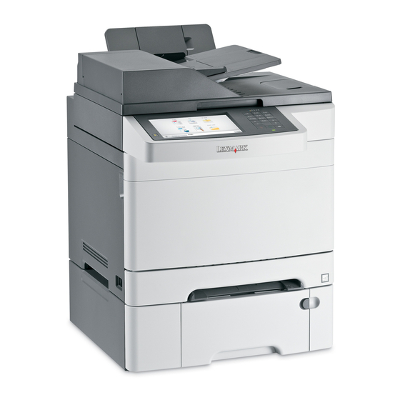
1. General information Previous The Lexmark™ X548 Series MFPs combine print, scan, copy, and fax functions. They are the ideal MFPs for presentations, business graphics, line art, and text. They use laser diode electrophotographic technology to deliver remarkable quality print images and text. The scan and copy functions work with A4, letter, and legal Next (ADF only) size paper. -
Page 24: Memory
7525-63x Memory Previous Memory Optional slots One slot Next Standard DIMM 512MB sizes Go Back Optional (DDR2) 256MB, 512MB and 1GB Maximum printer 1536MB memory Flash memory 256MB Option Slots (single slot is available for either font or flash memory card) Font card support 1 font card Optional user flash... -
Page 25: Connectivity (Network Support)
7525-63x Connectivity (network support) Previous Network protocol supported Standard Ethernet 10/100 Base T Next Standard USB-B (Full speed) device port USB-A host ports (In front, low/full speed) This port only supports the following Go Back flash drives and file types: - Supported flash drives: Lexar Jump Drive 2.0 Pro (256/512MB/1GB size) or SanDisk Cruzer Mini (256/512MB/1GB size) -
Page 26: Operating Modes
• The operator panel back light is off. • Power supply energy consumption is reduced. Energy + Paper: *Settings associated with Energy mode plus duplex are enabled. Data streams ✔ —Supported Lexmark ✘ —Not supported X548 Data streams ✔ PCL 6 emulation ✔... -
Page 27: Dimensions
✔ HTML Dimensions Model Height Width Depth Weight Lexmark X548de 463 mm (18.2 in.) 440 mm (17.3 in.) 597 mm (23.5 in.) 27.8 kg (61.3 lb) Lexmark X548dte 597 mm (23.5 in.) 440 mm (17.3 in.) 597 mm (23.5 in.) 32.1 kg (70.7 lb) -
Page 28: Clearances
7525-63x Clearances Previous Next 32.07 kg Go Back (70.71 lb) Description Clearances Rear 102 mm (4 in.) Right side 508 mm (20 in.) Front 152 mm (6 in.) Left side 76 mm (3 in.) 254 mm (10 in.) Service Manual... -
Page 29: Power And Electrical Specifications
7525-63x Power and electrical specifications Previous The following table specifies nominal average power requirements for the base printer configurations. All power levels are shown in Watts (W). Maximum current is given in Amperes (A). Printing states Next 0.2 W Sleep state 23 W Go Back Ready state... -
Page 30: Acoustics
7525-63x Acoustics Previous All acoustic measurements are made in accordance with ISO 7779-1999 and reported in conformance with ISO9296:1988-04-15. Next Declared sound Operating mode pressure level Idle (standby mode) 23 dB Go Back Simplex printing (mono) 47 dB Simplex printing (color) 48 dB Duplex printing (mono) 49 dB... -
Page 31: Media Handling
MP feeder count as two independent input sources. The MF feeder is configured as “cassette” does not show up as Configure MP in the Paper Menu. Duplex capability Duplex Type ✔ —Supported Automatic duplex Models ✔ Lexmark X548dte General information... -
Page 32: Media Input Size Specifications
7525-63x Media input size specifications Previous ✔ —Supported without size sensing ✘ —Not supported Next Go Back Input source ✔ ✔ ✔ ✔ ✔ ✔ 210 x 297 mm (8.3 x 11.7 in.) ✘ ✔ ✔ ✔ ✔ ✔ 148 x 210 mm (5.83 x 8.3 in.) ✘... - Page 33 7525-63x Previous ✔ —Supported without size sensing ✘ —Not supported Next Input source Go Back ✘ ✘ ✘ ✘ ✔ ✔ 7¾ Envelope 98 x 191 mm (3.9 x 7.5 in.) ✘ ✘ ✘ ✘ ✔ ✔ 9 Envelope 98 x 225 mm (3.9 x 8.9 in.) ✘...
-
Page 34: Media Input Type Specifications
7525-63x Media input type specifications Previous ✔ —Supported ✘ —Not supported Next Input type Go Back ✔ ✔ ✔ ✔ ✔ ✔ Plain paper ✘ ✔ ✔ ✔ ✔ ✔ Card stock ✘ ✘ ✔ ✔ ✔ ✔ Transparency ✔ ✔... -
Page 35: Media Guidelines
(16–28 pound) grain long bond. The duplex unit does not support card stock, transparencies, envelopes, and labels. Lexmark transparency part numbers 12A8240, and 12A8241 are supported from the standard tray, manual slot and the multipurpose feeder. Paper 90 to 104.9 g/m (23.9 to 27.8 lb) must be printed with Paper Type set to Heavy Paper. -
Page 36: Unacceptable Paper
7525-63x between 100 and 300 Sheffield points; however, smoothness between 150 and 200 Sheffield points Previous produces the best print quality. • Moisture content—The amount of moisture in paper affects both print quality and the ability of the printer to feed the paper correctly. Leave paper in its original wrapper until it is time to use it. This limits the exposure of paper to moisture changes that can degrade its performance. -
Page 37: Storing Paper
US, fed as well as non-recycled paper. However, no blanket statement can be made that all recycled paper will feed well. Lexmark consistently tests its printers with recycled paper (20–100% post-consumer waste) and a variety of test paper from around the world, using chamber tests for different temperature and humidity conditions. -
Page 38: Digital Imaging Specifications
7525-63x Previous Digital imaging specifications General specifications Next ADF scan speed Simplex ADF—Up to 5 ppm • Duplex ADF—Up to 5 ppm (page sides) Go Back • ADF document handling ADF input capacity—50 sheets • • ADF output capacity—50 sheets ADF document width—4.9 in. -
Page 39: Scan And Copy Specific Specifications
Scan and copy specific specifications Previous Scan resolutions Optical—600 dpi (Local TWAIN only) • Enhanced (via Lexmark Scan Center)—1200 x 1200 dpi, 2400 x 2400 dpi, 4800 x 4800 dpi, • Next 9600 x 9600 dpi, 19200 x 19200 dpi Output resolutions Go Back Mono—600 x 600 dpi... -
Page 40: Fax Specifications
7525-63x Previous Fax specifications Phone network connectivity Phone networks types supported PSTN or analog PABX (RJ-11) Next ITU compatibility Group 3/ECM Mono resolution Go Back Standard resolution 8 x 3.85 pels/mm (200 x 100dpi) (204 x 98) Fine 8 x 7.7 pels/mm (200 x 200dpi) (204 x 196) Superfine 11.8 x 11.8 pels/mm (300 x 300 dpi) (204 x 391) Ultrafine... -
Page 41: Tools Required For Service
7525-63x Previous Tools required for service Flat-blade screwdrivers, various sizes #1 Phillips screwdriver, magnetic #2 Phillips screwdriver, magnetic Next #2 Phillips screwdriver, magnetic short-blade 7/32-inch (5.5 mm) open-end wrench 7.0-mm nut driver Go Back Needlenose pliers Diagonal side cutters Spring hook Feeler gauges Analog or digital multimeter Parallel wrap plug 1319128... -
Page 42: Acronyms
7525-63x Previous Acronyms Alternating Current Autocompensator Mechanism (or paper feed) Automatic Document Feeder Next ASIC Application Specific Integrated Circuit Cyan Charge Coupled Device Go Back CMYK Cyan, magenta, yellow, and black Cyclic redundancy check Customer Replaceable Unit Direct Current DIMM Dual Inline Memory Module DRAM Dynamic Random Access Memory... - Page 43 7525-63x POST Power-on self test Previous PPDS Personal Printer Data Stream Pages per minute Random access memory Relative humidity Scanner Control Card Next Short edge feed Toner Patch Sensing Universal Serial Bus Go Back Volts V ac Volts alternating current V dc Volts direct current VOIP...
- Page 44 7525-63x Previous Next Go Back Service Manual 1-22...
-
Page 45: Diagnostic Information
The following is an example of the events that occur during the POR sequence when the printer is turned on. Display screen illuminates and the memory test is initiated. The Lexmark splash screen is displayed with a progress bar. The firmware revision is displayed in the lower left portion of the screen. -
Page 46: Symptoms Tables
7525-63x Previous Symptoms tables Printer symptoms table Symptom Action Next Dead printer Go to “Dead printer service check” on page 2-34. Operator panel—one or more buttons do Go to “One or more operator panel buttons fail” on Go Back not work. page 2-41. -
Page 47: Scan / Fax / Copy Symptom Table
7525-63x Scan / fax / copy symptom table Previous Symptom Action 840.xx scanner error Go to “840.xx error service check” on page 2-59. ADF won’t duplex (Duplex ADF only). Go to “ADF duplex service check” on page 2-65. Next ADF skew Go to “ADF feed errors service check”... -
Page 48: Print Quality Symptoms Table
7525-63x Print quality symptoms table Previous Symptom Action Background Go to “Print quality—background” on page 2-46. Blank page Go to “Print quality—blank page” on page 2-47. Next Blurred or fuzzy print Go to “Print quality—blurred or fuzzy print” on page 2-49. -
Page 49: Error Codes And Messages
7525-63x Previous Error codes and messages User status and attendance messages User primary message Explanation Next 290–294 ADF scanning The scanner failed to feed one or more pages through the ADF. jams 1. Remove all original documents from the ADF. Go Back Note: The message clears when the pages are removed from the ADF. - Page 50 7525-63x User status and attendance messages Previous User primary message Explanation No analog phone line The analog phone line was not detected; the fax is disabled. Connect the printer to connected to modem, an analog phone line, and then touch Continue. fax is disabled Next Some held jobs were...
- Page 51 7525-63x User status and attendance messages Previous User primary message Explanation 31.xx Defective [color] The specified toner cartridge is either missing or not functioning properly. Try one or cartridge more of the following: • Remove the specified toner cartridge, and then reinstall it. Next •...
- Page 52 7525-63x User status and attendance messages Previous User primary message Explanation 54 Standard network Try one or more of the following: software error • Touch Continue to continue printing. Next • Turn the printer off and then back on to reset the printer. •...
- Page 53 7525-63x User status and attendance messages Previous User primary message Explanation 84.xx [color] imaging kit 1. Order a replacement imaging kit. nearly low 2. When print quality is reduced, install the new imaging kit, following the instruction sheet that came with the replacement part. Next 3.
-
Page 54: 2Xx Paper Jam Messages
7525-63x User status and attendance messages Previous User primary message Explanation 840.01 Scanner Print without the scanner or contact your system support person. disabled by admin Next 840.02 Scanner The printer identified a problem with the scanner and automatically disabled it. Try disabled. - Page 55 7525-63x 2xx paper jam messages Previous Error code Description Action 202.xx Paper Jam A single page of media is jammed at Open the printer rear door to access the Check <area> the exit sensors. jam area. Remove the jammed page. See Next “202 paper jam”...
- Page 56 7525-63x 2xx paper jam messages Previous Error code Description Action 291.00 Scanner Jam, Scanner ADF detects paper at the Open the ADF cover to access the jam remove all originals second scanner sensor while the ADF area. Remove all the jammed pages. See Next from the scanner is in an idle state.
-
Page 57: Service Error Messages
7525-63x Service error messages Previous Error code Description Action 1xx.xx service errors Next 106.xx Service Yellow printhead error. Perform a POR. If the problem persists, go Yellow Printhead “Printhead service check” on page 2-54. Go Back 106.01 Service The yellow printhead lost HSYNC. Perform a POR. - Page 58 7525-63x Service error messages Previous Error code Description Action 107.08 Service The cyan laser showed bad in EMS Perform a POR. If the problem persists, go Cyan Printhead testing. “Printhead service check” on Next page 2-54. 107.11Service Failure writing data to printhead Perform a POR.
- Page 59 7525-63x Service error messages Previous Error code Description Action 109.02 Service The black printhead failed to complete Perform a POR. If the problem persists, go Black Printhead servo. “Printhead service check” on Next page 2-54. 109.03 Service The black printhead mirror motors Perform a POR.
- Page 60 7525-63x Service error messages Previous Error code Description Action 122.13 Service Fuser open thermistor check failed for Go to “Fuser service check” on Fuser Error second thermistor. page 2-38. Next 122.14 Service Fuser shorted thermistor check failed Go to “Fuser service check” on Fuser Error for hot roll thermistor.
- Page 61 7525-63x Service error messages Previous Error code Description Action 152.xx Service Go to “Main drive gear assembly (EP CMY Cartridge Motor drive) service check” on page 2-40. Next 152.01 Service Failed to achieve lock for motor within Go to “Main drive gear assembly (EP CMY Cartridge Motor allotted time.
- Page 62 7525-63x Service error messages Previous Error code Description Action 844.03 Rear scan module lamp level too low Rear Mono channel, Rear Color channels, Rear Red channel, Rear Green channel, Next and/or Rear Blue channel is detected to have low lamp level. Go to “CCD service check”...
- Page 63 7525-63x Service error messages Previous Error code Description Action 846.06 Front calibration strip has excessive Front excessive variability for Mono, Red, dark area. Green, or Blue. Go to “CCD service Next check” on page 2-60. 846.07 Front magnification exceeds limits Rear excessive variability for Mono, Red, Green, or Blue.
- Page 64 7525-63x Service error messages Previous Error code Description Action 907.xx Service A general engine software error. Go to “90x.xx error (902.xx–907.xx) Engine Software service check” on page 2-31 Next 908.01 Service Board level was not obtained. Engine Software Go Back 908.02 Service Timeout waiting for bullet serial data to Engine Software...
- Page 65 7525-63x Service error messages Previous Error code Description Action 950.xx Service There is a mismatch between controller Go to “950.xx NVRAM failure service NVRAM Failure EEPROM and mirror. check” on page 2-32. Next • 950.00 through 950.29 codes— Mismatch between controller and mirror.
- Page 66 7525-63x Service error messages Previous Error code Description Action 958.xx Service Printer has performed more than 100 NAND Failure “shift and reflash” operations as a Next result of ECC bit corrections. 959.01 Service Controller verification failure of pensive Update firmware or replace RIP board. Go Invalid Firmware boot code.
- Page 67 7525-63x Service error messages Previous Error code Description Action 964.xx Service Download emulation cyclic redundancy The following actions may be taken: Emulation Error check (CRC) failure has occurred. A 1. Disable the Download Emulation. Next checksum failure detected in the 2.
-
Page 68: Fax Error Log Codes
7525-63x Fax error log codes Previous Error code Description Action No error occurred during fax No action needed. transmission. Next Error occurred when transmitting • Check line quality. training. • Select a lower Max Speed value under Fax Send settings. Go Back •... - Page 69 7525-63x Fax error log codes Previous Error code Description Action Too many errors when transmitting in • Check line quality. ECM mode. • Adjust Transmit Level. Next • Select a lower Max Speed value under Fax Send settings. Remote device failed to respond to the •...
- Page 70 7525-63x Fax error log codes Previous Error code Description Action Failure to transmit training successfully • Select a lower Max Speed under Fax in V.17, V.27 terminal modulation Send settings. Next schemes. • Adjust Transmit Level. • Check line quality. Failure to transmit training successfully •...
- Page 71 7525-63x Fax error log codes Previous Error code Description Action Received request for unsupported No action needed. function from remote fax device. Next Received request for unsupported No action needed. image width from remote fax device. Go Back Received request for unsupported No action needed.
-
Page 72: Service Checks
Note: Before troubleshooting, determine the operating system used when the error occurred. If possible determine whether a PostScript or PCL file was sent to the device when the error occurred. Ask the customer which Lexmark Solutions applications are installed on the device. Step Action and questions POR the device. - Page 73 Reinstall the memory, and send a print job to Go to step 15. Go to step 16. the device. Does the 900.xx error reoccur? Install a Lexmark recommended memory Go to step 31. Problem resolved. option. Send a print job to the device. Does the 900.xx error reoccur? Go to step 17.
- Page 74 7525-63x Previous Step Action and questions Reinstall the modem. Restart the device. Go to step 18. Go to step 20. Does the 900.xx error reoccur? Next Upgrade the firmware. Contact your next level Go to step 19. Problem resolved. of support for the correct firmware level to use.
-
Page 75: 90X.xx Error (902.Xx-907.Xx) Service Check
7525-63x Previous Step Action and questions Replace the faulty ISP option. Restart the Go to step 31. Go to step 26. device. Does the 900.xx error reoccur? Next Contact your next level of support. You will need the following information for them: •... -
Page 76: 950.Xx Nvram Failure Service Check
7525-63x 950.xx NVRAM failure service check Previous Warning: Replace one of the following components, and perform a POR before replacing a second component. Never replace both of the components without performing a POR after installing each one, or the printer will be rendered inoperable: Operator panel assembly •... -
Page 77: Bin Full Sensor Service Check
7525-63x Previous Step Questions / actions Turn the printer on, and then verify the Replace the Replace the RIP board. See following approximate values at JSP1: autocompensator “RIP board removal” on mechanism. See page 4-19. JSP1 “Autocompensator Next mechanism (ACM)— Value standard tray removal”... -
Page 78: Dead Printer Service Check
7525-63x Dead printer service check Previous A dead printer is a condition where the display is blank, the LED on the operator panel is off, the fan does not turn, no motors turn, and the fuser does not heat. If a 650-sheet duo drawer is installed, remove the option and check the base printer for correct operation. If the Next base printer operates correctly, replace the 650-sheet duo drawer. -
Page 79: Duplex/Manual Feed Sensor (S1) Service Check
7525-63x Duplex/manual feed sensor (S1) service check Previous Note: Before performing this service check, ensure that the printer is on a hard level surface. Step Questions / actions Next Enter the Diagnostics Menu. Go to step 2. Go to step 4. 1. -
Page 80: Front Door Sensor Or Switches Service Check
7525-63x Front door sensor or switches service check Previous Step Questions / actions POR the device into Diagnostics mode. Sensor, toner door, and Go to step 2. right doors are OK. Next 1. Turn off the printer. 2. Press and hold 3 and 6. 3. -
Page 81: Fuser Exit Sensor Service Check
7525-63x Previous Step Questions / actions Close the front cover and the toner door. Be Contact your next level of Replace the front cover sure the right cover is in place. Turn the printer support. assembly. See “Front off, and then disconnect the cables at JINT1 cover assembly removal”... -
Page 82: Fuser Service Check
7525-63x Previous Step Questions / actions Make sure the printer is turned off. Disconnect Replace the fuser exit Replace the RIP board. See the cable at the sensor and at JBIN1 on the sensor. See “Fuser exit “RIP board removal” on RIP board. -
Page 83: Input Sensor (S2) Service Check
7525-63x Previous Step Questions / actions Disconnect the cable at JFUSES1 on the RIP Go to step 6. Replace the RIP board. See board, and check the following voltages: “RIP board removal” on page 4-19. JFUSES1 Next Value +24 V dc (doors closed) Go Back +24 V dc (doors closed) +24 V dc (doors closed) -
Page 84: Main Drive Gear Assembly (Ep Drive) Service Check
7525-63x Previous Step Questions / actions Turn the printer off, and remove the rear Go to step 4. Reseat the connector. shield. See “Rear shield removal” on page 4-7. Next Is the JSP1 cable connector properly connected to the RIP board? Turn the printer on, and check the voltage at Replace the Replace the RIP board. -
Page 85: Operator Panel Service Checks
7525-63x Operator panel service checks Previous Warning: Replace one of the following components, and perform a POR before replacing a second component. Never replace both of the components without performing a POR after installing each one, or the printer will be rendered inoperable: Operator panel assembly •... -
Page 86: Operator Panel Display Is Blank
7525-63x Operator panel display is blank Previous Step Questions / actions Check the cable connections between the RIP Go to step 3. Go to step 2. board and the UICC, and check the Next connections from the UICC to the display. Are the cables properly connected? Go Back Reconnect the cables. -
Page 87: Op Panel Usb Cable Service Check
7525-63x Previous Step Questions / actions Replace the UICC. POR the device into Problem resolved. Contact your next level of diagnostics mode. support. Next Does this fix the problem? Op panel USB cable service check Go Back Step Questions / actions Check the op panel USB cable for continuity. -
Page 88: Networking Service Check
Next interference. Have the network administrator verify that the device is using the correct SSID, and wireless security protocols. For more network troubleshooting information, consult the Lexmark Network Setup Guide. Go Back Step... -
Page 89: Print Quality Service Checks
7525-63x Previous Step Questions / actions Using the subnet address supplied by the Problem resolved. Go to step 12. network admin, assign a unique IP address to the printer. Note: The printer IP address should match Next the IP address on the printer driver. Did this fix the problem? Go Back Go to step 13. -
Page 90: Print Quality-Background
Measure all voltages from the connector to the printer ground. Print quality—background Next Service tip: Some background problems can be caused by rough papers, non-Lexmark toner cartridges or if the media texture is set to the rough setting. Go Back Some slick or coated papers may also cause background problems. -
Page 91: Print Quality-Blank Page
7525-63x Previous Step Questions / actions Replace the HVPS. See Problem resolved. Go to step 8. “High-voltage power supply (HVPS) with spring assembly removal” on page 4-40. Next Does this fix the problem? Clean the printhead. Problem resolved. Replace the printhead. See Go Back “Printhead removal”... - Page 92 7525-63x Previous Step Questions / actions 1. Remove the imaging unit and waste toner Go to step 5. Replace the Main drive gear bottle. assembly. See “Main drive 2. Replace the right cover and close the front gear assembly with motor door.
-
Page 93: Print Quality-Blurred Or Fuzzy Print
7525-63x Print quality—blurred or fuzzy print Previous Run the automatic alignment. The TPS sensor may be damaged. To run Reset Color Cal: Enter the Diagnostics Menu. Next a. Turn off printer. b. Press and hold 3 and 6. c. Turn on the printer. Go Back d. -
Page 94: Print Quality-Horizontal Line
7525-63x Previous Step Questions / actions Replace the developers that Check the various rollers in Does the distance measure 44 or 46 mm? match the missing color the printer for debris. (black, cyan, magenta, or yellow). See “Developer Next unit removal” on page 4-47. -
Page 95: Print Quality-Mottle (2-5Mm Speckles)
7525-63x Print quality—mottle (2–5mm speckles) Previous Keep running prints through, and the problem normally clears up. If the problem persists, replace the developer cartridge. Next Go Back Print quality—narrow vertical line ABCDE ABCDE ABCDE Step Questions / actions Replace the photoconductor unit. See Problem solved. -
Page 96: Print Quality-Residual Image
7525-63x Print quality—residual image Previous Service tip: Install a new print cartridge, if available, before doing this service check. Residual image can be caused by the photoconductor, cleaning blade, and other parts ABCDE inside the print cartridge. ABCDE Next ABCDE Go Back Step Questions / actions... -
Page 97: Print Quality-Solid Color Page
7525-63x Print quality—solid color page Previous Service tip: A solid color page is generally caused by a problem in the high-voltage controller or an incorrect high voltage in the printing process resulting in toner development on the entire photoconductor drum. Next Go Back Step... -
Page 98: Print Quality-Vertical Banding
7525-63x Print quality—vertical banding Previous Replace the developer cartridge. Next Go Back Printhead service check This service check includes the following errors: Error codes Color 106.xx Yellow 107.xx Cyan 108.xx Magenta 109.xx Black Step Questions / actions Turn the printer off, and remove the rear Replace the printhead. -
Page 99: Toner Meter Cycle (Tmc) Card Service Check
7525-63x Toner meter cycle (TMC) card service check Previous Step Questions / actions Perform the Base Sensor Test: Replace the toner cartridge. Replace the toner meter cycle (TMC) card. See Next 1. Enter the Diagnostics Menu (Turn off the “Toner meter cycle (TMC) printer, press and hold 3 and 6, turn on the card removal”... -
Page 100: Transfer Roll Service Check
7525-63x Transfer roll service check Previous Step Questions / actions Remove the ITU. See Replace the ITU. See Problem resolved. “Image transfer unit 4-43. Check the (ITU) removal” on page “Image transfer unit (ITU) Next contacts between the HVPS and the ITU. removal”... -
Page 101: Option Trays 2 And 3 Service Check
7525-63x Previous Step Questions / actions Turn off the printer, and remove the rear Problem resolved. Replace the RIP board. See shield. “Rear shield removal” on page 4-7. “RIP board removal” on Disconnect the cable at JTRAY1 connector for page 4-19. - Page 102 7525-63x Previous Step Questions / actions Check the option cable connected to JOPT1 Go to step 8. Go to step 7. for continuity. Is there continuity? Next Replace the cable and print from both option Problem resolved. Go to step 8. trays.
-
Page 103: 840.Xx Error Service Check
7525-63x Previous Scanner / Copy / Fax service checks 840.xx error service check Next Step Questions / actions POR the device into Configuration mode. Go Go to step 2. Stop. Problem resolved. Go Back to Disable Scanner and select Enabled. See 3-39. -
Page 104: Black Or Blank Page Copy Service Check
7525-63x Previous Step Questions / actions Inspect JFBM1, JHS1 and JCCD1 on the RIP Go to step 10. Go to step 9. board. Are they properly connected? Next Properly connect all the connections. Stop Problem solved. Go to step 10. Go Back Did the 840.xx error reoccur? Replace the flatbed unit. -
Page 105: Flatbed Motor Service Check
7525-63x Previous Step Questions / actions Go to step 3. Properly connect the ribbon Is the CCD ribbon cable properly connected cable to JCCD1. to JCCD1 on the RIP board? Replace the flatbed unit. See Problem resolved. Replace the RIP board. See “Flatbed Next removal”... -
Page 106: Adf Cover Open Service Check
7525-63x Previous Step Questions / actions Check pin 1 in JHS1 for voltage. The voltage Replace the flatbed unit. Replace the RIP board. Go should measure +5 V dc. pin 2 should be GND. “Flatbed removal” on “RIP board removal” on page 4-75. -
Page 107: Adf Streak Service Check
7525-63x ADF streak service check Previous Step Questions / actions Clean the ADF glass on the No issue to fix. Do streaks appear on the middle of scans flatbed using a lint-free Next when using the ADF? cloth. Also, clean the separator roll and pad with a damp cloth. -
Page 108: Adf Feed Errors Service Check
7525-63x Previous Step Questions / actions Inspect the connections on the ADF relay card Go to step 11. Secure all the connections. in the ADF. Are all the connections properly Next connected? Check the ADF cable for continuity. Go to step 11. Replace the ADF cable. -
Page 109: Adf Duplex Service Check
7525-63x Previous Check the ADF cable for continuity. Go to step 6. Replace the ADF cable. See “ADF cable removal” on page 4-89. Is there continuity? Replace the ADF. Go to Problem resolved. Replace the RIP board. Go “Duplex ADF removal”... -
Page 110: Modem/Fax Card Service Check
7525-63x Modem/fax card service check Previous Step Questions / actions Go to step 2. Go to step 3. Is the phone line properly connected to the Next modem card and the wall jack? Properly connect the phone line to the modem Problem resolved. -
Page 111: Fax Transmission Service Check
7525-63x Fax transmission service check Previous Note: Before performing this service check, verify that the correct country code for the MFP is selected. This setting must match the country in which the MFP is used to transmit and receive faxes. If the setting is wrong, the modem settings can be changed in the Fax/SE menu. -
Page 112: Fax Reception Service Check
7525-63x Previous Step Questions / actions Press **411 to enter the Fax/SE Menu. Select Problem resolved. Go to step 15. “Print Logs”. Print the T.30 transmission log. Check the error being reported with the fax error code Next table. See 2-27. - Page 113 7525-63x Previous Step Questions / actions Set “Enable Fax Receive” to On. Problem resolved. Go to step 9. Did this fix the problem? Next Go to step 11. Go to step 10. Is Distinctive Ring enabled? Turn on Distinctive ring. Problem resolved.
-
Page 114: Escalating A Fax Issue To Next Level Support
7525-63x Previous Step Questions / actions Adjust the “Receive Threshold” setting in the Problem resolved. Go to step 20. SE menu. press **411 to enter the SE menu, enter Modem settings, and select “Receive Threshold”. Next Test by adjusting the received signal level by decreasing/increasing the”Receive Threshold”... - Page 115 7525-63x Fill in the requested information. This is where you will type in the information you retrieved in step 3. Previous Second-level support can assist you if you have questions about the information requested on the page. Next Go Back Note: The fields requesting the code levels, model number, type of problem are auto-filled.
- Page 116 7525-63x Previous Next Go Back Service Manual 2-72...
-
Page 117: Diagnostic Aids
7525-63x 3. Diagnostic aids Previous This chapter explains the tests and procedures to identify printer failures and verify repairs have corrected the problem. Next User operator panel, menus and messages Go Back Understanding the operator panel WXYZ PQRS Operator panel buttons Item Function Display... -
Page 118: Understanding The Home Screen
7525-63x Previous Item Function USB port Insert a flash drive to send data to the printer or to scan a file to the flash drive. Home Press to return to the home screen. Next Submit • Press to initiate the current job indicated on the display. •... -
Page 119: Other Buttons That May Appear On The Home Screen
7525-63x Previous Icon/Button Function Access the printer menus. Note: These menus are available only when the printer is in the Ready state. Next Access the File Transfer Protocol (FTP) menus and scan documents directly to an FTP server. Go Back •... -
Page 120: Menu Map
7525-63x Previous Icon/Button Function Cancel Jobs Open the Cancel Jobs screen. The Cancel Jobs screen shows three headings: Print, Fax, and Network. The following options are available under the Print, Fax, and Network headings: • Print job Next • Copy job •... -
Page 121: Menu Key Combinations
7525-63x Menu key combinations Previous There are different test menus that can be accessed during POR to identify problems with the printer. Configuration Menu 1. Turn off the printer. The Configuration Menu group contains a set of menus, settings, and operations which are 2. -
Page 122: Diagnostics Menu (Diag Menu)
7525-63x Previous Diagnostics Menu (Diag Menu) Note: Tray 2 refers to the 650-sheet tray located in the 650-sheet duo drawer assembly. Diagnostics Menu structure Next When the Diagnostics mode is entered, each Diagnostics main menu item displays on the operator panel. When a diagnostic test is selected from the main menu, a sub menu displays, and each individual test displays in the Go Back order shown. - Page 123 7525-63x Sensor Test Previous “Sensor Test” on page 3-20. BASE SENSOR TEST Front Door “BASE SENSOR TEST” on page 3-20. Standard Bin Narrow Media Next Input - S1 Input - S2 Go Back Fuser Exit C TMC Sensor M TMC Sensor Y TMC Sensor K TMC Sensor DEVICE TESTS...
- Page 124 7525-63x Previous EVENT LOG Display Log “Display Log” on page 3-25. Print Log “Print Log” on page 3-25. Clear Log “Clear Log” on page 3-26. Do not use. For development use only. Next DEVELOPMENT MENU SCANNER TESTS ASIC Test “ASIC Test” on page 3-26.
-
Page 125: Printer
7525-63x REGISTRATION Previous Printer Print registration makes sure the black printing is properly aligned on the page. This is one of the steps in aligning a new printhead. See 3-11. It is also the first step in aligning the duplex “Alignment Menu”... -
Page 126: Quick Test
• General printer information, including current page count, installed memory, serial number, and code level • Lexmark x54x To print the Quick Test page: Note: Print the Quick Test Page on Letter or A4 paper. Navigate to REGISTRATION > Quick Test. -
Page 127: Alignment Menu
7525-63x Alignment Menu Previous Aligns each of the color planes to the black plane. Print the Quick Test under each color, Cyan, Yellow, and Magenta, and adjust the Top Margin, Left Margin, Right Margin, Skew, and Bow. Prints the Print Alignment Pages and requires that the best line in each set of lines must be selected. Next To get started: Navigate to Alignment Menu. - Page 128 7525-63x Select the best choice for fine or coarse adjustment in Step 1 (first page), and add it to the current value for Previous the Top Margin. Next Go Back Use the of the Top Margin setting to enter the sum of the numbers, and touch Submit. Submitting changes appears, and the display returns to the Alignment Menu.
-
Page 129: Factory Scanner
7525-63x Select the Skew value in the same way, and touch Submit. Print the Alignment pages to see if the Previous observed values and the current values are the same. Next Go Back On the second page of the latest Quick Test pages printed, proceed to Step 2; adjust the left, right, and bow settings. -
Page 130: Scanner Calibration
7525-63x Scanner Calibration Previous Copy Quick Test This test performs a copy from the scanner flatbed or duplex ADF using the printer’s current settings. Next To perform this test, navigate to Diag Menu > Scanner Calibration > Copy Quick Test. Adjust Calibration Values Go Back This setting adjusts the black value (mono and color bands) used in the gamma curve for a specific scan source. -
Page 131: Print Tests
7525-63x PRINT TESTS Previous Input source tests The purpose of the diagnostic PRINT TESTS is to verify that the printer can print on media from each of the installed input options. The contents of the Print Test Page vary depending on the media installed in the selected Next input source. -
Page 132: Print Quality Pages
The print quality test consists of five pages. Pages one and two contain a mixture of graphics and text. The remainder of the pages contain only graphics. The test prints on the media in Tray 1. Lexmark x54x Next Go Back This test may be printed from either Configuration Menu or the Diagnostics Menu. -
Page 133: Button Test
7525-63x Button Test Previous This test verifies the operator panel button function. To run this test: Navigate to HARDWARE TESTS > Button Test. Next An image of the operator panel buttons appears on the LCD. Press each operator panel button, and see if its corresponding button on the LCD darkens. -
Page 134: Duplex Tests
This test prints a duplex version of the Quick Test that can be used to verify the correct placement of the top margin on the back side of a duplex page. Next Go Back Lexmark x54x Note: Before you set the duplex top margin, be sure to set the registration. See “REGISTRATION” on page 3-9. -
Page 135: Top Margin (Duplex)
7525-63x Touch to adjust the margin setting. Previous • Each increment shifts the duplex left margin by 4 pixels at 600 dpi (0.00666 inches or 0.1693 mm). The Left Margin (duplex) range is -25 to + 25, and the default value is 0. •... -
Page 136: Sensor Test
7525-63x Sensor Test Previous This test is used to verify that the sensors are working correctly for an individual input tray. Navigate to INPUT TRAY TESTS > Sensor Test. Select the tray where you want to test the sensors. Depending on the tray selected, you may have Empty Next Sensor, Low Sensor, or Pass thru Sensor. -
Page 137: Device Tests
7525-63x DEVICE TESTS Previous Flash Test This test appears only when a non-defective flash memory is installed. Data is written to the flash card and read back to check the accuracy. This test destroys all data stored on the flash device. Next Warning: This test deletes all data stored on the flash device. -
Page 138: Prt Color Pg Count, Prt Mono Pg Count And Perm Page Count
7525-63x Prt Color Pg Count, Prt Mono Pg Count and Perm Page Count Previous These page counts can only be viewed and cannot be changed. To view these settings: Next Navigate to PRINTER SETUP. Navigate to the page count you wish to view: •... -
Page 139: Itu Barcode
7525-63x Touch Submit to save the settings, or touch Back to return to PRINTER SETUP without saving any Previous changes. Note: If either Configuration ID is invalid, Invalid ID appears. The printer discards the changes and the display returns to PRINTER SETUP. If both Configuration IDs are valid, Submitting changes appears and the display returns to PRINTER SETUP. -
Page 140: Fuser Temp
7525-63x Fuser Temp Previous This adjustment can be used to help solve some problems of paper curl on low-grade papers and/or melting of letterheads on some types of media. To change this setting: Next Navigate to EP SETUP > Fuser Temp. Touch to select Normal, High, or Low. -
Page 141: Reports
• Time and date stamps Page counts for most errors • Additional debug information in some cases • Model and Lexmark x54x (s/n: 98P104V) Serial number Printer information Panel display when error occurred Page count Earliest error code The printed event log can be faxed to your next level of support for verification or diagnosis. -
Page 142: Clear Log
7525-63x Clear Log Previous Use Clear Log to remove the current information in the Event Log. This affects both the viewed log and the printed log information. Navigate to EVENT LOG > Clear Log. Next Touch YES to clear the Event Log, or NO to exit the Clear Log menu. SCANNER TESTS Go Back ASIC Test... -
Page 143: Adf Paper Present Sensor Test
7525-63x ADF paper present sensor test Previous This test should be used if the ADF fails to feed paper when a scan is performed. To test this sensor: ADF Paper Present: 0 appears. Open the ADF top cover. Next Press and hold the ADF paper present sensor actuator (A) at the top of the ADF unit. Go Back The value of ADF Paper: should change from 0 to 1 if the sensor is working properly. -
Page 144: Adf Cover Open Sensor Test
7525-63x Press and hold the FB cover actuator (A). Previous Next Go Back The value of FB Cover: should change from 1 to 0 if the sensor is working properly. Press to return to SCANNER TESTS. ADF cover open sensor test This test verifies the functionality of the ADF cover closed sensor. -
Page 145: Scan 1St Sensor Test
7525-63x Scan 1st sensor test Previous This test verifies the functionality of scan sensor 1. To test this sensor. perform the following steps: Scan 1st Sensor: 0 appears. Lift the ADF top cover, and close the ADF cover sensor by pressing down on the ADF sensor actuator (A) Next with a small flat-blade screwdriver. -
Page 146: Scanner 2Nd Sensor Test
7525-63x Scanner 2nd sensor test Previous This test verifies the functionality of scan Sensor 2. To test this sensor, perform the following steps: Scan 2nd Sensor: 0 appears. Lift the ADF top cover, and close the ADF cover sensor (A) by pressing down on the ADF sensor actuator Next with a small flat-blade screwdriver. -
Page 147: Scanner Calibration Reset
7525-63x Scanner Calibration Reset Previous This procedure should be run after the scanner or ADF has been replaced. ADF Magnification Next This setting enables the adjustment of the ADF’s magnification. To adjust this setting: Go Back Navigate to SCANNER TESTS > ADF Magnification. Touch to adjust the setting. -
Page 148: Configuration Menu
7525-63x Previous Configuration Menu Available tests The tests display on the operator panel in the order shown: Next Reset Separator Roll and Pick “Reset Separator Roll and Pick Assembly Counter” on Assembly Counter page 3-33. Go Back USB Scan to Local “USB Scan to Local”... -
Page 149: Reset Separator Roll And Pick Assembly Counter
7525-63x Reset Separator Roll and Pick Assembly Counter Previous To reset the counter: Navigate to Reset Separator Roll and Pick Assembly Counter. Touch Reset Separator Roll and Pick Assembly Counter to reset the counter. Next Resetting appears, and the display returns to Reset Separator Roll and Pick Assembly Counter. USB Scan to Local Go Back USB Scan to Local enumerates a USB simple device or USB composite device. -
Page 150: Event Log
7525-63x Event Log Previous Lets the system support person print a limited set of the information contained in the Diagnostics Menu version of the printed Event Log. For a sample of a printout, see 3-25. The limited Configuration “Event Log” on page log and the full Diagnostics log printed versions show the same operator panel messages when they print and follow the same layout guidelines. -
Page 151: Ppds Emulation
7525-63x PPDS Emulation Previous The value of the PPDS Emulation menu item determines if a device can recognize and use the PPDS data stream. The current value of this setting appears in parentheses to the right of the setting on the Configuration Menu screen. -
Page 152: Energy Conserve
7525-63x To reset factory defaults: Previous Navigate to Factory Defaults. Choose the setting to reset: Restore Base—resets all non-critical base NVRAM settings • Restore STD NET—resets the eSF configuration • Next • Restore LES—resets all network NVRAM settings Restoring Factory Defaults appears, followed by Resetting the Device. The printer performs a POR. Go Back Energy Conserve Affects the values that display in the Sleep Mode setting in the General Settings Menu. -
Page 153: Numpad Job Assist
7525-63x NumPad Job Assist Previous This setting determines if a user can configure and initiate a job using the panel’s hard buttons. To change this setting: Next Navigate to NumPad Job Assist. Touch to change the setting. Touch Submit to save the setting, or touch Back to return to the Configuration Menu without saving any Go Back changes. -
Page 154: Adf Edge Erase
7525-63x ADF Edge Erase Previous This menu item sets the size, in millimeters, of the no-print area around an ADF scan job. All copy jobs have a two-millimeter minimum border. Copy jobs will use the setting or two millimeters, whichever is larger. To adjust this setting: Next Navigate to ADF Edge Erase. -
Page 155: Disable Scanner
7525-63x Disable Scanner Previous This menu item is used to disable the MFP scanner if it is malfunctioning. The MFP must be powered off and on for the new settings to take effect. To change this setting: Next Navigate to Disable Scanner. Touch to change the setting. -
Page 156: Font Sharpening
7525-63x Font Sharpening Previous This setting is used to set a text point size value below which the high frequency screens will be used when printing data. This setting affects only PCL, PostScript, and PDF emulators. Settings are in the range of 0–150 (24 is the default). For example, if the value is set to 24, then all fonts sized 24 Next points or less use the high frequency screens. -
Page 157: Key Repeat Initial Delay
7525-63x Key Repeat Initial Delay Previous When a key is touched repeatedly, this is the delay before the key begins repeating. The range is 0.25–5 seconds, with increments of 0.25. The default is value is 1 second. To adjust this setting: Next Navigate to Key Repeat Initial Delay. -
Page 158: Usb Pnp
7525-63x USB PnP Previous This setting is used to improve the MFP’s compatibility with the host PC. Note: Some PCs contain chipsets that may be incompatible with this MFP. Next To change this setting: Navigate to USB PnP. Touch to change the setting. Go Back Touch Submit to save the setting, or touch Back to return to the Configuration Menu without saving any changes. -
Page 159: Se Menu
7525-63x Previous SE Menu Note: This is not the Fax SE menu. To enter the Fax SE menu, press **411 from the Ready screen. Note: This menu should be used as directed by next level of support. Next Print Se Menus Go Back GENERAL Copyright—Displays copyright information... -
Page 160: Invalid Engine Code Mode
NVRAM or in the hard drive, therefore, a RIP board failure could result in loss of these applications and settings if they are not backed up. When a new RIP board is installed, the Lexmark default eSF applications and settings are loaded. -
Page 161: Paper Jams
Next Use only recommended paper or specialty media. • For more information, see the Card Stock & Label Guide available on the Lexmark Web site at Go Back www.lexmark.com/publications. Do not load too much paper. Make sure the stack height does not exceed the indicated maximum height. -
Page 162: Understanding Jam Numbers And Locations
7525-63x Understanding jam numbers and locations Previous When a jam occurs, a message indicating the jam location appears. The following illustration and table list the paper jams that can occur and the location of each jam. Open doors and covers, and remove trays to access jam locations Next Go Back... -
Page 163: 200 Paper Jam
7525-63x 200 paper jam Previous Pull out the standard 250-sheet tray (Tray 1). Grasp the jammed paper on each side, and gently pull it out. Note: Make sure all paper fragments are removed. Next Go Back Insert the tray. From the printer display, touch Continue, jam cleared. Diagnostic aids 3-47... - Page 164 7525-63x 201 paper jam Previous CAUTION—HOT SURFACE: The inside of the printer might be hot. To reduce the risk of injury from a hot component, allow the surface to cool before touching. Next Open the front cover. Go Back Grasp the jammed paper on each side, and gently pull it out. Note: Make sure all paper fragments are removed.
-
Page 165: 202 Paper Jam
7525-63x 202 paper jam Previous CAUTION The inside of the printer might be hot. To reduce the risk of injury from a hot component, allow the surface to cool before touching. Next Raise the scanner assembly to the up position. Go Back Open the front cover. -
Page 166: 230 Paper Jam
7525-63x Hold the fuser cover down, and remove the jam. Previous Note: Make sure all paper fragments are removed. • • The fuser cover closes when released. Next Go Back Close the fuser cover. Close the front door. From the printer display, touch Continue, jam cleared. 230 paper jam Open the front cover. -
Page 167: 241 Paper Jam
7525-63x 241 paper jam Previous Pull out the standard 250-sheet tray (Tray 1). Grasp the jammed paper on each side, and gently pull it out. Note: Make sure all paper fragments are removed. Next Go Back Insert the tray. From the printer display, touch Continue, jam cleared. Diagnostic aids 3-51... -
Page 168: 242, 243 Paper Jam
7525-63x 242, 243 paper jam Previous Note: Since the 650-sheet duo drawer and 550-sheet tray are similar in function, only the procedure for clearing the 650-sheet duo drawer is shown. Pull out the 650-sheet duo drawer (Tray 2) or the 550-sheet tray (Tray 3). Grasp the jammed paper on each side, and then gently pull it out. -
Page 169: 290-294 Adf Paper Jams
7525-63x 290–294 ADF paper jams Previous Remove all original documents from the ADF input tray. Open the ADF cover. Remove the jammed paper. Next Go Back Close the ADF cover. Open the flatbed cover. Remove any jammed pages. Note: Make sure all paper fragments are removed. Close the scanner lid. -
Page 170: Xx Adf Paper Jams
Updating printer firmware The latest firmware can be found by going to and inputting http://support.lexmark.com/printerfirmware keycode x54x (all lowercase). Before performing a firmware update on the printer, contact the technical service center or second level of support to verify the correct firmware and keycode. The wrong firmware or wrong level of firmware could lead to a malfunction or render the printer inoperable. -
Page 171: Theory Of Operation
7525-63x Previous Theory of operation Print engine theory Next Electrophotographic process (EP process) The method that all laser and LED printers use to print is called the electrophotographic process. These machines use differences in charge to manipulate and move toner from the toner cartridge to the printed page. Go Back Even though the basic EP process is the same for every laser and LED printer, the specifics for each printer are different. -
Page 172: Step 1: Charge
7525-63x Step 1: Charge Previous During the charge step, voltage is sent from the high-voltage power supply to the charge roller (A) beside each of the four photoconductors. The charge roller is part of the photoconductor unit. The charge roller (A) puts a uniform negative charge over the entire surface of the photoconductor to prepare it Next for the laser beam. -
Page 173: Step 2: Expose
7525-63x Step 2: Expose Previous During the expose step, the laser fires a focused beam of light at the surface of each photoconductor (B) and writes an invisible image called a latent image or electrostatic image for each color. The laser beam actually discharges the surface only where the beam hits the photoconductor. This creates a Next difference in charge potential between the exposed area and the rest of the photoconductor surface. -
Page 174: Step 3: Develop
7525-63x Step 3: Develop Previous Once the laser exposes the photoconductor, the high-voltage power supply sends charge to the developer roll (C). For each color, the toner cartridge engages the photoconductor so it is in contact with the surface. Because of the charge difference between the toner on the developer roller and the electrostatic image created by the laser, the toner will attract to the photoconductor only where the laser exposed the surface. -
Page 175: Step 4A: First Transfer
7525-63x Step 4a: First transfer Previous When the latent images are developed on each Photoconductor, the high-voltage power supply sends voltage to the 1st Transfer Rollers inside the ITU (D). The charge difference between the developed toner image on the Photoconductor surface and the 1st Transfer Next Roller causes the images to transfer to the surface of the ITU belt for each color. -
Page 176: Step 4B: Second Transfer
7525-63x Step 4b: Second transfer Previous Once the four planes of color are transferred to the transfer belt from the photoconductors, the image is carried towards the transfer roll (E). This transfer roll is also part of the ITU. Based on the speed of the transfer belt, the proper time to send the signal to pick the media from an input source is determined. -
Page 177: Step 5: Fuse
7525-63x Step 5: Fuse Previous Once the image has been fully transferred to the media, the transfer roll helps move the paper into the fuser area. The fuser (F) applies heat and pressure to the page to melt the tiny toner particles and bond them permanently Next to the media. -
Page 178: Step 6: Clean/Erase
7525-63x Step 6: Clean/Erase Previous There are two main cleaning processes that take place during the EP Process. One process cleans the transfer belt, and the other cleans the photoconductors. Transfer Unit Clean Next Once the toner image on the transfer belt has been transferred to the page, the transfer belt rotates around and is cleaned by the cleaning blade (G). - Page 179 7525-63x Photoconductor Clean/Erase Previous After each plane of color has been transferred to the transfer belt from the photoconductors, a cleaning blade (H) scrapes the remaining toner from the surface of each photoconductor. This is the clean/erase process. Now the photoconductor surface is prepared to begin the EP cycle once again. This cleaning/erasing cycle happens after each plane of color is transferred to the transfer belt.
-
Page 180: Paper Path Transport Components
7525-63x Paper path transport components Previous In order for an image to be printed, the media has to be moved from an input source (such as a tray) into the printer and eventually exit into an output source. The most important component in this process is this media itself. Old, damaged, or out-of-specification media Next can and will cause feed and transport problems. -
Page 181: Transport Components
7525-63x Transport components Previous In summary, the media is fed from the tray into the printer by a feed roll and carried to the transfer roll (ITU). The pick rollers time the media to enter the EP process at just the right moment. The pick rollers push the media to the ITU where the image is transferred to the page. -
Page 182: Scanner Theory
7525-63x When the trailing edge of the media clears the fuser, the fuser engine rotates forward to prepare the fuser for the Previous page travelling through the duplexer. As the media reaches the gate aligner, a sensor (S1) is triggered indicating the presence of the leading edge. When the S1 sensor is triggered, the paper continues to the S2 sensor. -
Page 183: Color Theory
7525-63x When the document sensor is actuated, a signal is sent to flatbed to move the CCD imaging unit to the Previous ADF scan area. When the CCD reaches the ADF scan area, a calibration is performed on the CCD. The media is advanced to ADF scan sensor which is located by the takeaway roll. - Page 184 7525-63x How does the printer know what color to print? Previous When a user prints a document, information describing the type and color of each object is sent to the printer. The color information is passed through color conversion tables that translate the color into the appropriate amounts of cyan, magenta, yellow, and black toner needed to produce the desired color.
- Page 185 7525-63x Touch to select Manual from the Color Correction setting. Previous Touch Submit to save the setting. The display returns to the Print Settings menu. Navigate to Manual Color. Select the appropriate color conversion table for the affected object type. Next Object type Color conversion tables...
- Page 186 7525-63x What are detailed Color Samples and how do I access them? Previous Detailed Color Samples sets are available only through the Embedded Web Server of a network printer. A detailed Color Samples set contains a range of shades (displayed as colored boxes) that are similar to a user- defined RGBor CMYK value.
-
Page 187: Repair Information
7525-63x 4. Repair information Previous Warning: Read the following before handling electronic parts. Next Handling ESD-sensitive parts Go Back Many electronic products use parts that are known to be sensitive to electrostatic discharge (ESD). To prevent damage to ESD-sensitive parts, use the following instructions in addition to all the usual precautions, such as turning off power before removing logic boards: Keep the ESD-sensitive part in its original shipping container (a special “ESD bag”) until you are ready to •... -
Page 188: Removal Procedures
7525-63x Previous Removal procedures CAUTION Remove the power cord from the electrical outlet before you connect or disconnect any cable Next or electronic board or assembly for personal safety and to prevent damage to the printer. Disconnect any connections between the printer and PCs/peripherals. Go Back Notes: Some removal procedures require removing cable ties. -
Page 189: Front Cover Assembly Removal
7525-63x Front cover assembly removal Previous Remove the media tray. Open the front cover. Remove the front middle cover (optional). See “Front middle cover removal” on page 4-4. Remove the five screws (A) from the cable cover. Next Remove the cable cover. Remove the screw (B) securing the right restraining strap to the front cover. -
Page 190: Front Middle Cover Removal
7525-63x Front middle cover removal Previous Open the front cover. Remove the five screws (A) securing the front middle cover to the lower front cover. Next Go Back Pull the front middle cover away from the front cover. Left cover removal Note: Some printers may have a filter installed on the fan grill. - Page 191 7525-63x Remove the three screws (A) on the rear side of the left cover. Previous Next Go Back Repair information...
- Page 192 7525-63x Remove the screw (B) on the bottom of the cover. Previous Next Go Back With a hand on the bottom of the cover, ease the cover over the off/on switch, and rotate the cover away from the printer. Warning: Be careful not to damage the rear tab at the upper rear side of the cover. Installation note: When replacing the left cover, flex the cover slightly to engage the tab near the power switch.
-
Page 193: Right Cover Removal
7525-63x Right cover removal Previous Lift and lock the flatbed assembly to the raised position. Open the front cover. Release the green latches securing the door. Lower the right cover and remove it from the hinges. Next Go Back Rear shield removal The rear shield is not a field replaceable unit (FRU). -
Page 194: Aio Back Cable Cover Removal
7525-63x AIO back cable cover removal Previous Note: Some printers may have a filter installed on the fan grill. Remove the filter first before continuing with the removal procedure. Next Go Back Remove the two screws (A) securing the AIO back cable cover to the MFP. Service Manual... -
Page 195: Top Cover Assembly Removal
7525-63x Place a small flat-blade screwdriver under the bottom of the cover, and gently pry the cover upward. Previous Next Go Back Top cover assembly removal Remove the flatbed assembly. Go to “Flatbed removal” on page 4-75. Remove the AIO toner cover. Go to “AIO toner cover removal”... - Page 196 7525-63x Remove the screw (B) from the top right side of the cover. Previous Next Go Back Remove the four screws (C) on the right side of the top cover. Service Manual 4-10...
- Page 197 7525-63x Remove the toroid holder (D) and two screws (E) from the rear. The toroid holder will be used for the new Previous top cover. Next Go Back Detach the re-drive belt (F) from the pulley on the fuser exit roll shaft. Disconnect the fan power cable from JFAN1 on the RIP board.
- Page 198 7525-63x Installation notes: Previous Warning: Make sure the belt is attached to the gear (B), Also; check the tension spring to make sure it is properly attached to the top cover (C). The following illustration shows the properly attached spring and belt.
-
Page 199: Autocompensator Mechanism (Acm)-Standard Tray Removal
7525-63x Autocompensator mechanism (ACM)—standard tray removal Previous Remove the toner bottles, the waste toner bottle, and the imaging unit (IU). See “Imaging unit (IU) removal” on page 4-63 “Waste toner bottle removal” on page 4-73. Remove the rear shield. See “Rear shield removal”... - Page 200 7525-63x Remove the two springs (D). Previous Next Go Back Remove the two screws (E) on the bottom. Service Manual 4-14...
- Page 201 7525-63x On the right side, loosen the screw (F), and hold the ACM in place as you use your fingers to remove the Previous screw. Next Go Back Move the right side of the ACM out to free the shaft from the hole in the frame. Note: Observe the location of the shaft and hole for reinstallation.
-
Page 202: Bin Full Sensor Removal
7525-63x Bin full sensor removal Previous Remove the flatbed unit. See “Flatbed removal” on page 4-75. Using a small flat-blade screwdriver, gently depress the tabs (A) which secure the sensor to the top cover assembly. Next Go Back Pull the sensor away from the top cover assembly. Disconnect the sensor from the cable. -
Page 203: Narrow Media Sensor Flag Removal
7525-63x Narrow media sensor flag removal Previous Open the front cover. Remove the narrow media sensor flag. Remove the cable from the retainer. Note: Be sure to note the routing for reinstallation. Next Disconnect the cable (A) from the narrow media sensor. Go Back Repair information 4-17... - Page 204 7525-63x If there is a sensor retaining plate (B), remove the plate. Previous Next Go Back Squeeze the retainers on the rear of the sensor, and gently remove the sensor from the bracket by hand. Installation notes: Clean the contact surface where you removed the sensor retaining plate, or where you need to install the new one.
-
Page 205: Rip Board Removal
7525-63x RIP board removal Previous Warning: Observe all ESD precautions while handling electrostatic-discharge sensitive parts. See “Handling ESD-sensitive parts” on page 4-1. Warning: When replacing any one of the following components: Next • Operator panel assembly RIP board • Replace only one component at a time. Replace the required component, and perform a POR before Go Back replacing a second component listed above. - Page 206 7525-63x Disconnect all the cables from the RIP board. Previous Next Go Back Remove the six screws (B) securing the RIP board to the RIP board cage. Service Manual 4-20...
- Page 207 7525-63x Remove the board. Previous Next Go Back Installation note: Perform the Motor detect test and Scanner manual registration after replacing the RIP board. “Motor Detect” on page 3-14 “Scanner Manual Registration” on page 3-38. Warning: Do not start the machine into Ready state to test it. See “Testing generic FRUs”...
- Page 208 7525-63x Tuck the printhead cable toroid (C) as shown below. Failure to do so can damage the RIP board. • Previous Next Go Back Note: Pay attention to the jumper configuration (D). An improper configuration will cause the printer to malfunction.
-
Page 209: Duplex Reference Edge Removal
7525-63x Duplex reference edge removal Previous Note: If the duplex reference edge is made of plastic, then replace it. If the duplex reference edge is made of metal, then do not replace it. Next Go Back Plastic Metal Open the front door. Remove the four short screws (A) in front, and the four longer screws (B) in the back of the duplex aligner. - Page 210 7525-63x Lift the duplex aligner on the right side, and disengage the gears (C) on the left. Previous Next Go Back Remove the four screws (D) from the duplex reference guide, and remove the guide. Service Manual 4-24...
- Page 211 7525-63x Installation notes: Previous Depending on the kind of front cover, follow the procedure that applies: If the front cover has a slot • Place the tab in the slot. Slot Next Go Back Repair information 4-25...
- Page 212 7525-63x Rotate the tab into position, and replace the three screws (A). Previous Next Go Back Service Manual 4-26...
- Page 213 7525-63x If the front cover does not have a slot • Previous Place the tab against the cover. Next Go Back Replace the two screws (B). Repair information 4-27...
- Page 214 7525-63x Be sure the shaft and bearing have not shifted out of the guide, and that the bearing on the left is aligned Previous with the slot (C) facing down (towards the front door). Note: Improperly aligned bearings or shafts incorrectly seated may cause vibration and noise in the front door.
-
Page 215: Duplex Sensor Removal
7525-63x Duplex sensor removal Previous Remove the waste toner bottle. See “Waste toner bottle removal” on page 4-73. Remove the two screws (A) from the cable channel cover. Next Go Back Pull the corner of the cable channel cover (B) away from the right side to access the sensor posts (C). Repair information 4-29... - Page 216 7525-63x If there is a plate on the side of the sensor latches connected, remove the old adhesive plate (D). Previous Next Go Back Unlatch the sensor by pushing on the latches. Remove the sensor, and disconnect the cable (E) from the duplex sensor. Note: Close the front cover, and slightly lift the front of the printer to get better access.
-
Page 217: Fax Card Removal
7525-63x Fax card removal Previous Remove the rear shield. See “Rear shield removal” on page 4-7. Disconnect the fax card cable (A) from the RIP board. Next Go Back Open the fax card cover, and remove the three screws (B) from the fax card. Repair information 4-31... -
Page 218: Fuser Assembly Removal
7525-63x Remove the fax card from the standoff. Previous Next Go Back Fuser assembly removal Remove the right cover. See “Right cover removal” on page 4-7. Remove the left cover. See “Left cover removal” on page 4-4. Disconnect the two-wire fuser cable (A) from the LVPS. Position the fuser cable so that it can be pulled through from the front of the printer, and guide the cable to the front. - Page 219 7525-63x Disconnect the two thermistor cables (C) from the fuser. Previous Next Go Back Unhook the springs (D) from either side of the fuser. Detach the geared belt (E) from the drive pulley on the fuser exit roll shaft. Note: Do not remove the pulley or spacer from the shaft. Rotate the top of the fuser toward the front, slide it to the left to align the fuser side frame with the flat areas of the shaft (F) and lift to remove the fuser.
- Page 220 7525-63x Warning: Be careful not to interfere or damage the fuser exit sensor located to the left of the fuser. Previous Next Go Back Service Manual 4-34...
- Page 221 7525-63x Installation notes: Previous • Install the narrow media sensor flag to the fuser before putting the fuser into the printer. Make sure the springs are resting on the top so they can be reached once the fuser is in place. •...
-
Page 222: Fuser Drive Motor Assembly Removal
7525-63x Fuser drive motor assembly removal Previous Open the front cover. Remove the right cover. See “Right cover removal” on page 4-7. Disconnect the cable (A) from the fuser drive motor assembly. Note: If the toroid (B) is removed from the cable, be sure to reinstall the toroid when reconnecting the Next cable. -
Page 223: Fuser Exit Sensor Removal
7525-63x Fuser exit sensor removal Previous Open the front cover. Remove the right cover assembly. See “Right cover removal” on page 4-7. Remove the left cover. See “Left cover removal” on page 4-4. Disconnect the two-wire fuser cable (A) from the LVPS. Next Note: You do not have to extract the cable. - Page 224 7525-63x Disconnect the narrow medial sensor cable and remove the cable from the fuser frame. See “Narrow Previous media sensor flag removal” on page 4-17. Note: Observe the cable routing. Unhook the springs (D) from both sides of the fuser. Next Go Back Rotate the fuser toward the front of the printer until the screw (E) can be accessed, and removed.
-
Page 225: Hard Drive Removal
7525-63x Hard drive removal Previous Remove the rear shield. See “Rear shield removal” on page 4-7. Disconnect the hard drive cable (A) from the RIP board. Next Go Back Pull the hard drive and remove. Repair information 4-39... -
Page 226: High-Voltage Power Supply (Hvps) With Spring Assembly Removal
7525-63x High-voltage power supply (HVPS) with spring assembly removal Previous Remove the left cover. Note: There should be a leaf spring (A) biasing the HVPS upward. Next Go Back Remove the rear shield. See “Rear shield removal” on page 4-7. Remove the RIP board. - Page 227 7525-63x Remove the screw (B) securing the HVPS. Previous Next Go Back Press down on the spring mount and carefully slide the HVPS out. Release the pressure on the spring mount when the LVPS slides out about 25mm. Repair information 4-41...
- Page 228 7525-63x Installation notes: Previous CAUTION After disconnecting the high-voltage power cable from the RIP board, always check that the HVPS connection was not loosened. Make this check anytime you are working near the HVPS cable. Next Warning: Connect the high-voltage power supply (HVPS) cable to the high-voltage power supply before sliding the board into the printer.
-
Page 229: Image Transfer Unit (Itu) Removal
7525-63x Image transfer unit (ITU) removal Previous Write down the number on the new ITU before installing it. You will need the 16-digit numeric value from the barcode after the installation, and it is easier to see at this point. Remove the right cover. - Page 230 7525-63x Remove the rubber pad (C). Previous Place the spring clamp onto the shaft (D). Snap the new gear onto the shaft (D). The installation is the same as the old gear. Next Go Back Service Manual 4-44...
-
Page 231: Continuing The Removal (With Or Without Spring Clamp Kit)
7525-63x Continuing the removal (with or without spring clamp kit) Previous Disconnect the one spring (A) from the side frames, leaving them attached to the ITU or spring clamp. Next Go Back Rotate the left spring (B) and pivot the cam away from the ITU so the spring is held out of the ITU path. Repair information 4-45... - Page 232 7525-63x Rotate the release lever (C) in a counter clockwise direction with a spring hook or needlenose pliers to Previous decouple the ITU while pulling the ITU toward the front. Next Go Back Hold the release lever while removing the ITU. Installation notes: Write down the 16-digit numeric value of the new FRU before you begin to install it.
-
Page 233: Developer Unit Removal
7525-63x After replacing the ITU, be sure to enter the 16-digit numeric value of the new ITU: • Previous Enter the Diagnostics Menu: Turn off the printer. Press and hold 3 and 6. Turn on the printer. Release the buttons when the progress bar appears. Next Navigate to PRINTER SETUP >... -
Page 234: Low-Voltage Power Supply (Lvps) Assembly Removal
7525-63x Low-voltage power supply (LVPS) assembly removal Previous Next Remove the left cover. See “Left cover removal” on page 4-4. Disconnect the three cables (A) from the LVPS. Go Back Remove the six screws (B) and the ground cable connected to the LVPS cage. Service Manual 4-48... - Page 235 7525-63x Remove the LVPS. Previous Warning: If you receive a new low-voltage power supply with a voltage selector switch (C), be sure to set the switch to the correct setting for your voltage requirements before installing the low-voltage power supply. The switch can be set for either 115 V or 230 V. Failure to do so will result in damage to the power supply.
-
Page 236: Left Lower Frame And Right Lower Frame Removal
7525-63x Left lower frame and right lower frame removal Previous The left lower frame and right lower frame are in the same FRU. Left lower frame Next Remove the media tray, and remove the screw (A) in front. Go Back Remove the waste toner bottle. - Page 237 7525-63x At the rear of the printer, remove the ground screw (C) and two screws (D) from the AC receptacle. Previous Next Go Back Remove the three screws (E) securing the left lower frame. Remove the LVPS. See “Low-voltage power supply (LVPS) assembly removal” on page 4-48.
- Page 238 7525-63x Remove the screw (F) on top of the frame. Previous Next Go Back Swing the left lower frame away from the printer, and remove. Service Manual 4-52...
-
Page 239: Right Lower Frame
7525-63x Right lower frame Previous Note: Remove the duplex sensor, the tray present sensor, the spring, spring holder, and the wireless antenna plate which are not part of the right and left lower frames. The cable cover is part of the right lower frame FRU. - Page 240 7525-63x Remove the three screws (C) securing the lower right frame to the printer. Previous Remove the screw (D) close to the front of the printer. Next Go Back Swing the rear part away from the printer to access the spring, and remove the spring (E) from the right lower frame.
- Page 241 7525-63x Lift the right lower frame pin (F) out of the hole in the printer frame. Previous Next Go Back Swing the rear part away from the printer to access the spring (G), and remove it from the right lower frame.
- Page 242 7525-63x Swing the rear of the lower frame away from the printer, and remove the right lower frame. Previous Note: There are parts in the right lower frame that are not included in the frame. The following instructions show how to remove them. Remove the sensor retaining plate (J), and press the latches (K) together to remove the tray present sensor.
-
Page 243: Main Drive Gear Assembly With Motor Removal
7525-63x Remove the backing from the new plates, and place them on the surfaces (A) between the sensor Previous mounting posts. Note: Make sure the clips on the posts extend onto the surface of the plate. Next Go Back Connect the cable to the tray present sensor, and put the spring in place before installing the right lower frame. - Page 244 7525-63x Remove the two screws (B) from the inner left side. Previous Next Go Back Disconnect the cable from the fuser exit sensor. Remove the screws securing the LVPS shield. Unplug the cables (C) from the motors, and remove all cables from the retainer (D). Note: Pay attention to the cable routing for reinstallation.
- Page 245 7525-63x Remove the two screws (F) from below the main drive gear assembly. Previous Remove the two screws (G) from the right of the main drive gear assembly. Next Go Back Lift the main drive gear assembly with motor, and remove. Repair information 4-59...
-
Page 246: Pick Tires Removal-Integrated 250-Sheet Media Tray
7525-63x Pick tires removal—integrated 250-sheet media tray Previous Note: You will need to have a soft, padded work surface. Warning: Remove only the rubber tires and not the paper pick tire assembly to avoid losing small parts. The paper pick tires are located in the base printer. There are also tires in the optional 550-page media tray. If Next you have this additional option, and you are having problems with media picking, replace these tires also. -
Page 247: Printhead Removal
7525-63x Installation notes: Previous Install the new rubber tires with the surface texture turning in the direction as shown. Next Go Back Note: Feel each rubber surface to verify it turns properly in the direction shown. Printhead removal Remove the scanner assembly. See“Flatbed removal”... - Page 248 7525-63x Remove the three screws (B). Previous Next Go Back Remove the printhead. Installation note: When the printhead is replaced, perform the registration (black planes) and alignment (color planes). See “REGISTRATION” on page 3-9 “Alignment Menu” on page 3-11. Service Manual 4-62...
-
Page 249: Imaging Unit (Iu) Removal
7525-63x Imaging unit (IU) removal Previous The imaging unit is customer replaceable unit and not a FRU. Note: The imaging unit contains: Photoconductor unit • Next Developer units • To remove only the photoconductor, remove the entire imaging unit, remove the developer units, place the Go Back original developer units in the new photoconductor, and reinstall the imaging unit. -
Page 250: Toner Cartridge Contacts Removal
7525-63x Toner cartridge contacts removal Previous Remove the right cover assembly. See “Right cover removal” on page 4-7. Remove the waste toner bottle. See “Waste toner bottle removal” on page 4-73. Remove the imaging unit. See “Imaging unit (IU) removal” on page 4-63. - Page 251 7525-63x Disconnect the cable (E) from the RIP board at JSC1. Previous Next Go Back Remove the cable from the retainer on the bottom of the printer. Extract the cable through the frame, and remove the cable with the spring contacts. Repair information 4-65...
-
Page 252: Toner Meter Cycle (Tmc) Card Removal
7525-63x Toner meter cycle (TMC) card removal Previous Remove the right cover. See “Right cover removal” on page 4-7. Remove the waste toner bottle. See “Waste toner bottle removal” on page 4-73. Remove the imaging unit (IU). See “Imaging unit (IU) removal” on page 4-63. - Page 253 7525-63x Installation notes: Previous • Be sure the cable runs through the retainer. The toner meter cycle card is a tight fit. Insert the bottom edge inside the frame, and then push down • on the top edge to clear the top cover. In some cases, the top cover will have to be loosened so the right edge of the top cover can be lifted •...
-
Page 254: Toner Patch Sensor (Tps)-Left And Right Removal
7525-63x Toner patch sensor (TPS)—left and right removal Previous The toner patch sensors are similar, but the left sensor includes an extra cable and sensing device. Remove them the same way. Remove the ITU. See “Image transfer unit (ITU) removal” on page 4-43. -
Page 255: Tray Present Sensor Removal
7525-63x Installation notes: Previous Whether you replace the left or right toner density sensors, be sure to perform the TPS Setup. Enter the 32-digit TPS value set at the factory and printed on the barcode on the toner density sensor. Enter the Diagnostics Menu: Turn off the printer. - Page 256 7525-63x Remove the screw (D) closer to the front of the printer. Previous Next Go Back Lift the right lower frame pin (E) out of the hole in the printer frame. Swing the rear of the lower frame away from the printer to access the tray present sensor latches. Service Manual 4-70...
- Page 257 7525-63x Remove and secure the spring (F) from the right lower frame. Previous Note: The spring easily gets lost. Next Go Back Disconnect the tray present sensor cable. Remove the sensor retaining plate (G), and then squeeze the latches together to remove the tray present sensor.
-
Page 258: Usb Connector Removal
7525-63x Remove the backing from the new plate, and place the plate on the surface between the sensor mounting Previous posts. Connect the cable to the tray present sensor. Replace the spring. USB connector removal Next Remove the rear shield. See “Rear shield removal”... -
Page 259: Waste Toner Bottle Removal
7525-63x Waste toner bottle removal Previous The waste toner bottle is a customer replaceable unit. Open the front cover. Lift the toner cover. Next Remove the right cover assembly. See “Right cover removal” on page 4-7. Press the two tabs (A) to release the waste toner bottle, and remove it. Go Back Repair information 4-73... -
Page 260: Waste Toner Bottle Contact Block Removal
7525-63x Waste toner bottle contact block removal Previous Open the front cover. Remove the right cover assembly. See “Right cover removal” on page 4-7. Remove the waste toner bottle. See “Waste toner bottle removal” on page 4-73. Remove the screw (A) from the back of the waste toner bottle contact block. Next Go Back Remove the rear shield. -
Page 261: Scanner Component Removal Procedures
7525-63x Previous Scanner component removal procedures Flatbed removal Remove the AIO rear cable cover. See Next “AIO back cable cover removal” on page 4-8. Remove the rear shield. See “Rear shield removal” on page 4-7. Remove the left cover. See “Left cover removal”... - Page 262 7525-63x Remove the second toroid (B) from the toroid holder, and slide it off the CCD cable. This toroid will also be Previous reused on the new flatbed unit. Next Go Back Remove the screw (C) that fastens the redrive ground cable and ADF ground cableground cable to the frame.
- Page 263 7525-63x Disconnect the operator panel ground cable (D) from the LVPS. Previous Next Go Back Thread the ground cable (E) under the top cover. Repair information 4-77...
- Page 264 7525-63x Disconnect the screw (F) connecting the flatbed to the AIO link on the rear of the MFP. Previous Next Go Back Carefully disconnect the AIO link from the flatbed. Remove the two screws (G) securing the flatbed hinge to the top cover. Remove the two springs (H) between the flatbed and top cover.
- Page 265 7525-63x Gently pry the front flatbed hinge (J) towards the front of the top cover to disengage it from the top cover Previous guide pin. Next Go Back Carefully pull the flatbed unit towards the front of the MFP while using your other hand to route the cables through the top cover.
- Page 266 7525-63x Remove the steel hinge stud (K). Save this for use on the replacement flatbed. Previous Next Go Back Remove the redrive unit (L). See “Redrive unit removal” on page 4-93. Remove the cable cover plates and scanner homing plates (M). These will be used on the replacement flatbed unit.
- Page 267 7525-63x Remove the screws (N) securing the flatbed link to the flatbed. Previous Next Go Back Remove the flatbed link. It will be used on the replacement flatbed unit. Note: The redrive, cable covers, operator panel assembly, scanner flatbed guides, op panel cable, and USB cable need to be transferred to the replacement flatbed unit.
-
Page 268: Preparing And Installing The New Flatbed
7525-63x Preparing and installing the new flatbed Previous Unbox the scanner, and place it top down on a non-marring surface. Next Go Back Unfold the ribbon cable, and replace the toroid (A) from the old flatbed. Service Manual 4-82... - Page 269 7525-63x Locate the folding guide line (B), and remove the paper backing from the adhesive strip located next to the Previous folding guide line on the scanner. Next Go Back Fold the ribbon cable as shown. Align the fold of the cable with the folding guide line on the flatbed. Press down the cable so that it sticks to the adhesive strip.
- Page 270 7525-63x Locate the second folding guide line (C), and remove the paper backing from the adhesive strip. Previous Next Go Back Fold the ribbon cable a second time as shown. Align the fold of the cable with the folding guide line on the flatbed.
-
Page 271: Flatbed Pivot Link Removal
7525-63x Flatbed pivot link removal Previous Remove the AIO link. See “AIO link removal” on page 4-97. Remove the right scanner cover. See “Scanner right cover removal” on page 4-94. Remove the AIO release lever. See “AIO release lever removal” on page 4-96. -
Page 272: Duplex Adf Rear Cover Removal
7525-63x Duplex ADF rear cover removal Previous While lifting the ADF, use a flat-blade screwdriver to pry open the three tabs (A) on the bottom of the ADF cover. Next Go Back Lift and remove the rear cover from the ADF assembly. Service Manual 4-86... -
Page 273: Duplex Adf Removal
7525-63x Duplex ADF removal Previous Remove the duplex ADF rear cover from the ADF assembly. See “Duplex ADF rear cover removal” on 4-86. Save the cover for use on the new ADF unit. page Disconnect the ground cable (A) from the ADF assembly. Disconnect the ADF cable (B) from the ADF card located on the ADF assembly. -
Page 274: Adf Input Tray Removal
7525-63x Remove the ADF assembly. Previous Note: After installing the new ADF unit, perform the scanner calibration procedure and the scanner manual registration procedure. See “Scanner Calibration” on page 3-14 “Scanner Manual Registration” on page 3-38. ADF input tray removal Next Firmly grasp the ADF input tray on both sides. -
Page 275: Adf Cable Removal
7525-63x ADF cable removal Previous Remove the the duplex ADF rear cover. See “Duplex ADF rear cover removal” on page 4-86. Remove the left cover. See “Left cover removal” on page 4-4. Remove the AIO back cable cover. See “AIO back cable cover removal” on page 4-8. - Page 276 7525-63x With your right hand, pull the relay card end of the ADF cable up and away from the ADF while using your Previous left hand to guide the ADF cable up through the card cage opening. Note: Be careful to avoid contact with the CCD ribbon cable. Next Go Back Feed the ADF cable up between the left flatbed cover and flatbed unit, and gently pull the cable up.
-
Page 277: Adf Separator Pad Removal
7525-63x ADF separator pad removal Previous Remove the ADF separator roll. See “ADF separator roll assembly removal” on page 4-92. Press the two tabs on each side of the pad inward. Next Go Back Tilt the pad up, and lift it out of the ADF assembly. Repair information 4-91... -
Page 278: Adf Separator Roll Assembly Removal
7525-63x ADF separator roll assembly removal Previous Lift the locking lever (A). Next Go Back Slightly lift the separator roll assembly, and pull it out of the mount (B) on the opposite side. Service Manual 4-92... -
Page 279: Redrive Unit Removal
7525-63x Redrive unit removal Previous Remove the flatbed assembly. See “Flatbed removal” on page 4-75. Place the flatbed facedown on a soft surface to avoid scratching the glass or marring the covers. Remove the cable cover plate (A). Remove the four screws (B) securing the redrive to the flatbed unit. Next Go Back Remove the bin full sensor flag located on the rear shaft. -
Page 280: Scanner Left Cover Removal
7525-63x Scanner left cover removal Previous Remove the flatbed assembly. See “Flatbed removal” on page 4-75. Release the tabs (A) securing the left flatbed cover to the flatbed unit using a small flat-blade screwdriver. Next Go Back Scanner right cover removal Remove the imaging unit in the print engine. - Page 281 7525-63x While holding the ADF away from the flatbed, use the other hand to lift and disengage the right scanner Previous cover from the flatbed unit. Next Go Back Repair information 4-95...
-
Page 282: Aio Release Lever Removal
7525-63x AIO release lever removal Previous Remove the right scanner cover. See “Scanner right cover removal” on page 4-94. Remove the screw (A) securing the AIO link to the flatbed unit. Next Go Back Disengage the AIO link from the flatbed unit. Remove the screw (B) securing the AIO release lever to the flatbed. -
Page 283: Aio Link Removal
7525-63x AIO link removal Previous Lift the scanner to the up position. Remove the screw (A) securing the AIO link to the AIO toner cover. Next Go Back Return the flatbed to the down position. Remove the screw (B) securing the AIO link to the flatbed unit. Repair information 4-97... -
Page 284: Aio Toner Cover Removal
7525-63x AIO toner cover removal Previous Lift the scanner unit to the up position. Remove the screw (A) fastening the AIO toner cover to the scanner unit. Next Go Back Remove the screws (B) securing the AIO hinge to the MFP. Remove the hinge (C). -
Page 285: Bin Full Flag Removal
7525-63x Bin full flag removal Previous Lift the scanner assembly, and lock it into the up position. Gently disconnect the three snaps (A) from the rear shaft of the redrive unit. Next Go Back Remove the bin full flag. Repair information 4-99... -
Page 286: Lcd Removal
7525-63x LCD removal Previous Remove the operator panel bezel. See “Operator panel bezel removal” on page 4-104. Remove the operator panel frame cover. See “Operator panel frame cover removal” on page 4-107. Remove the rear case with speaker. See “Rear case with speaker removal” on page 4-108. - Page 287 7525-63x Disconnect the two cables (B) from the user interface controller card. Previous Next Go Back Remove the LCD. Repair information 4-101...
-
Page 288: Operator Panel Assembly Removal
7525-63x The LCD with the ground cable is shown below: Previous Next Go Back Operator panel assembly removal Remove the AIO rear cable cover. See “AIO back cable cover removal” on page 4-8. Remove the rear shield. See “Rear shield removal” on page 4-7. -
Page 289: Operator Panel Cover With Light Pipe Removal
7525-63x Operator panel cover with light pipe removal Previous Remove the operator panel bezel. See “Operator panel bezel removal” on page 4-104. Remove the operator panel frame cover. See “Operator panel frame cover removal” on page 4-107. Remove the rear case with speaker. See “Rear case with speaker removal”... -
Page 290: Operator Panel Bezel Removal
7525-63x Operator panel bezel removal Previous Open the front door. Next Go Back Open the top door. Service Manual 4-104... - Page 291 7525-63x Remove the screw (A) from the joint linking the flatbed to the printer. Previous Warning: Do not over-extend the flatbed when lifting it after the screw (A) has been removed. Next Go Back Remove the three screws (B) under the operator panel. Repair information 4-105...
- Page 292 7525-63x Slightly pull the operator panel away from the printer, then pry the operator panel bezel off the operator Previous panel. Next Go Back Warning: During reinstallation, be sure to properly engage the tabs of the operator panel bezel to their corresponding slots.
-
Page 293: Operator Panel Frame Cover Removal
7525-63x Operator panel frame cover removal Previous Remove the operator panel bezel. See “Operator panel bezel removal” on page 4-104. Using a 1.0 Phillips screwdriver, remove the three screws (A) from the rear side of the operator panel. Next Go Back Remove the operator panel frame cover. -
Page 294: Output Bin Tray Removal
7525-63x Output bin tray removal Previous Grasp and lift the rear output bin tray away from the MFP. Next Go Back Rear case with speaker removal The rear case with speaker is not a field replaceable unit (FRU). Remove the operator panel bezel. See “Operator panel bezel removal”... - Page 295 7525-63x Pull the operator panel cover away from the rear case, and disconnect the four cables (B). Previous Next Go Back Route the cables off the rear case. Remove the rear case with speaker. Repair information 4-109...
-
Page 296: Sleep Button Removal
7525-63x Sleep button removal Previous Remove the operator panel bezel. See “Operator panel bezel removal” on page 4-104. Remove the operator panel frame cover. See “Operator panel frame cover removal” on page 4-107. Remove the rear case with speaker. See “Rear case with speaker removal”... -
Page 297: Speaker Removal
7525-63x Remove the sleep button PCB. Previous Next Go Back Speaker removal Remove the operator panel bezel. See “Operator panel bezel removal” on page 4-104. Remove the operator panel frame cover. See “Operator panel frame cover removal” on page 4-107. Remove the rear case with speaker. -
Page 298: Usb Cable Removal
7525-63x Remove the speaker. Previous Next Go Back USB cable removal Remove the AIO rear cable cover. See “AIO back cable cover removal” on page 4-8. Remove the rear shield. See “Rear shield removal” on page 4-7. Remove the left cover. See “Left cover removal”... -
Page 299: User Interface Controller Card Removal
7525-63x User interface controller card removal Previous Remove the operator bezel cover. See “Operator panel bezel removal” on page 4-104. Remove the operator panel frame cover. See “Operator panel frame cover removal” on page 4-107. Remove the rear case with speaker. See “Rear case with speaker removal”... - Page 300 7525-63x Remove the user interface controller card. Previous Next Go Back Service Manual 4-114...
-
Page 301: Locations
7525-63x 5. Locations Previous Exterior views Next Front Go Back Part name Operator panel Automatic Document Feeder (ADF) Standard exit bin Top door latch Right side cover Standard 250-sheet tray (Tray 1) Manual feeder 650-sheet duo drawer with integrated multipurpose feeder (Tray 2) Note: When used with the 550-sheet tray, the 650-sheet duo drawer must be stacked in the exact position shown in the illustration. -
Page 302: Rear
7525-63x Rear Previous Next Go Back Part name Power Line Extension Ethernet Service Manual... -
Page 303: Print Engine Interior View
7525-63x Print engine interior view Previous Next Go Back Locations... -
Page 304: Printer Boards
7525-63x Printer boards Previous RIP board JHS1 JMOD2 Next Go Back Service Manual... -
Page 305: Connectors
7525-63x Connectors Previous Connector Pin no. Signal JADF1 I0A_ADF_C I1A_ADF_C Next Ground DIRA_ADF_C Go Back Ground I0B_ADF_C I1B_ADF_C Ground DIRB_ADF_C Ground V_24_ADF V_24_ADF Ground V_5_ADF PAP_PRES2_2 VREF1_ADF_C VREF2_ADF_C PAP_PRES_C ADF_CVR_C FIRST_SCAN_C FB_CVR_C SOL1_EN_2 JBHUSB1 - Rear USB Host Port Ground V_BUSB USB_DM2 USB_DP1... - Page 306 7525-63x Previous Connector Pin no. Signal JCARTB1 CART1_HALL_U NC_CARTB1_2 CART1_HALL_V Next V_CART2_WIND_W CART1_HALL_W Go Back V_CART2_WIND_V CART1_PG V_CART2_WIND_U Ground Ground V_CART1_WIND_U CART2_PG V_CART1_WIND_V V_CART1_WIND_W V_CART1_WIND_W V_CART1_WIND_V NC_JCARTB1_19 V_CART1_WIND_U Service Manual...
- Page 307 7525-63x Previous Connector Pin no. Signal JCCD1 - CCD ribbon cable FBR_AFE_SDI FBR_AFE_SCK FBR_AFE_SEN Next FBR_AFE_D(0) Go Back FBR_AFE_D(1) FBR_AFE_D(2) FBR_AFE_D(3) FBR_AFE_D(4) FBR_AFE_D(5) FBR_AFE_D(6) FBR_AFE_D(7) FB_AFE_VSMP_R FB_AFE_RSMP_R FB_AFE_CLK_R FB_CCD_CLAMP_R FB_CCD_RESET_R FB_CCD_PHASE1_R FB_CCD_PHASE2_R FBR_CCD_TRANSFER +14V +14V FB_POWER_SAVER_R FB_LAMP_ON_R JCFAN1 FAN_PWM_PWR Ground FAN_SENSE Locations...
- Page 308 7525-63x Previous Connector Pin no. Signal JCTM1 CART_METER_C_IN CART_METER_M_IN Next CART_METER_Y_IN CART_METER_K_IN Go Back Ground JCVR1 V_24V_CVR, +24V dc COVER_OPEN (cover open +0V dc; closed: +24V JFAN1 FAN_FG Ground V_FAN_P3 JFBM1 - Flatbed Motor FB_A- FB_A FB_B FB_B- JFP1 I2CDATA LED_DRV_YLW2 I2CCLK Ground...
- Page 309 7525-63x Previous Connector Pin no. Signal JFUSES1 V_FUSER_PHA+, +24V dc (doors closed) V_FUSER_PHA-, +24V dc (doors closed) V_FUSER_PHB+, +24V dc (doors closed) Next V_FUSER_PHB-, +24V dc (doors closed) FUSER_HR_THM (AVCC), +2.3 V dc Go Back FUSER_HR_THM_RTN +5V_SW Ground S1_MPF_SNS FUSER_BELT FUSER_HR_THM_RTN Ground JHD1...
- Page 310 7525-63x Previous Connector Pin no. Signal JHVPS1 M_DEV_PWM_OUT K_DEV_PWM_OUT C_DEV_PWM_OUT Next CMY_CHG_PWM_OUT Y_DEV_PWM_OUT Go Back K_CHG_PWM_OUT CMY_SRVO_OUT ITM_TX_PWM_OUT CMY_TX_PWM_OUT ITM_SRVO_OUT K_SRVO_OUT K_TX_PWM_OUT +24V Ground 5V_HVPS_REF Ground JINT1 +5V Fused Ground VS_INT JLVPS1 Ground Ground Ground +24VC Ground +24VC Ground +24VC Ground RELAY_DRIVE ZERO_XING_IN...
- Page 311 7525-63x Previous Connector Pin no. Signal JMIRR1 MM_REFR MM_LOCK, +3.3 V dc MM_START Next +24V_VC Go Back JMOD2 NC_30V_CUHD NC_JMOD2_2 POR_CHUD_R- +3.3V +3.3V NC_TONE_CUHD IRQ_CUHD Ground SDA_CUHD Ground SCL_CUHD Ground CLK_CUHD Ground SDO_CUHD Ground SDI_CUHD Ground CS_CUHD JOPT1 TXD_PP Ground Ground RXD_PP +24V...
- Page 312 7525-63x Previous Connector Pin no. Signal JPH1 VDO_HSYNC1_C, + 5 V dc VDO_PH_OK, +3.3 V dc VDO_HSYNC0, + 5 V dc Next VDO_LEN0, +3.3 V dc VDO_BOOST3 Go Back +3.3V VDO_BOOST1 +5V_PH, + 5 V dc VDO_BOOST2 (Shade B) +5V_PH, + 5 V dc VDO_BOOST0 Ground D_VDO_7+...
- Page 313 7525-63x Previous Connector Pin no. Signal JPH1 (continued) Ground D_VDO_2+ D_VDO_2- Next Ground D_VDO_5+ Go Back D_VDO_5- Ground D_VDO_1+ D_VDO_1- Ground D_VDO_4+ D_VDO_4- Ground D_VDO_0+ D_VDO_0- Ground I2CCLK_PH VDO_LADJ1, + 3.3 V dc I2CDATA_PH VDO_LADJ, + 3.3 V dc JPJP1 +5V_SW PAPER_JAM_DET Ground...
- Page 314 7525-63x Previous Connector Pin no. Signal JSP1 ANODE (no wire) M1_OUT1, +24 V dc (0V dc with door open) CATHODE Next M1_OUT2, +24 V dc (0V dc with door open) (+5V SW) VCC Go Back Ground (no wire) Ground CATHODE VOUTA VOUTB ANODE...
- Page 315 7525-63x Previous Connector Pin no. Signal JUIC1 UI_RESET_NR Ground Y1M_LVDS Next Y1P_LVDS Y2M_LVDS Go Back Y2P_LVDS CLK_TX CLK_TX+ Ground 5.0 V dc RXD232_N TXD232_N Y0M_LVDS Y0P_LVDS Ground 5.0 V dc 5.0 V dc 5.0 V dc JUSB1 Port Ground USB_5V_Sense USB D- USB D+ Ground...
-
Page 316: Hvps
7525-63x HVPS Previous Next Go Back Service Manual 5-16... -
Page 317: Connectors
7525-63x Connectors Previous HVPS board Connector Pin no. Signal Connection from RIP board M-Drpwm Next K-Drpwm C-Drpwm Go Back CMY-Chrgpwm Y-Drpwm K-Chrgpwm CMY-Srvo_Out I-Txpwm CMY-Txpwm I-Srvo_Out K-Srvo_Out K-Txpwm +24V +24VRtn VREF Buffered +24VRtn Contacts to machine I-Transfer CMY-Transfer K-Transfer K-Charge CMY-Charge K-DR Blade M-DR Blade... -
Page 318: Lvps
7525-63x LVPS Previous Next Go Back Service Manual 5-18... -
Page 319: Connectors
7525-63x Connectors Previous LVPS board Connector Pin no. Signal +5 V Next Ground +5 V Go Back Ground +5 V Ground +24 V Ground +24 V Ground +24 V Ground Relay drive ZC out Heat On AC phase input AC neutral input AC out AC load phase Locations... -
Page 320: Toner Meter Card
7525-63x Toner meter card Previous Next Go Back Connectors Toner meter card Connector Pin no. Signal From JCTM1 connector on the RIP +5 V_SW board Cart_Meter_C_IN Cart_Meter_M_IN Cart_Meter_Y_IN Cart_Meter_K_IN Ground Service Manual 5-20... -
Page 321: Preventive Maintenance
Damaged, missing, or altered parts, especially in the area of the On/Off switch and the power supply • Damaged, missing, or altered covers, especially in the area of the top cover and the power supply cover • Possible safety exposure from any non-Lexmark attachments • Scheduled maintenance Customer replacable units (CRUs) The following parts also need to be checked for wear or damage, and replaced if necessary. -
Page 322: Lubrication Specifications
7525-63x Previous Lubrication specifications Lubricate only when parts are replaced or as needed, not on a scheduled basis. Use of lubricants other than those specified can cause premature failure. Some unauthorized lubricants may chemically attack polycarbonate parts. Use IBM no. 10 oil, P/N 1280443 (Approved equivalents: Mobil DTE27, Shell Tellus 100, Next Fuchs Renolin MR30), IBM no. -
Page 323: Cleaning The Scanner Glass
7525-63x Cleaning the scanner glass Previous Clean the scanner glass if you encounter print quality problems, such as streaks on copied or scanned images. Note: Clean both areas of the scanner glass and both white underside areas. Slightly dampen a soft, lint-free cloth or paper towel with water. Next Open the scanner cover. - Page 324 7525-63x Previous Next Go Back Service Manual...
-
Page 325: Parts Catalog
PP: (Parts Packet) in the parts description column indicates the part is contained in a parts packet. • Model information used in the parts catalog: • The Lexmark X548 series MFPs are available in the following models: Machine type/model Product name Description... -
Page 326: Assembly 1:Covers
7525-63x Assembly 1: Covers Previous Next Go Back Service Manual... - Page 327 7525-63x Assembly 1: Covers Previous Asm- Part Units/ Units/ Description index number mach 40X5484 Tray, Output bin Next 40X5489 Cover, AIO back cable 40X5482 Assembly, Top cover 40X5537 Link, AIO Go Back 40X5534 Cover, AIO toner 40X5486 Cover, Right AIO 40X5419 Tray asm, 250-sheet 40X5168...
-
Page 328: Assembly 2:Scanner
7525-63x Assembly 2: Scanner Previous Next Go Back Service Manual... - Page 329 7525-63x Assembly 2: Scanner Previous Asm- Part Units/ Units/ Description index number mach 40X5470 Tray, ADF input Next 40X5478 Cover, ADF rear duplex 40X5479 Cable, ADF 40X5872 Bin full flag Go Back 40X8342 Asm, Redrive 40X7529 Asm, LED flatbed 40X5536 Lever, AIO release 40X1569 Flatbed pivot link...
-
Page 330: Assembly 3:Operator Panel
7525-63x Assembly 3: Operator panel Previous Next Go Back Service Manual... - Page 331 7525-63x Assembly 3: Operator panel Previous Asm- Part Units/ Units/ Description index number mach 40X6523 Cover, Operator panel bezel Next 40X6521 Display, 7-inch LCD (with ground cable) 40X6519 Cover, Operator panel with keypads, sleep button and light pipe 40X6515 PCBA, UICC Go Back 40X6516 Cable, UICC...
-
Page 332: Assembly 4:Paperpath
7525-63x Assembly 4: Paperpath Previous Next Go Back Service Manual... - Page 333 7525-63x Assembly 4: Paperpath Previous Asm- Part Units/ Units/ Description index number mach 40X5411 Printhead Next 40X5415 Fuser drive motor assembly 40X5422 Bottom left and right frame and cable cover 40X5424 Screw packet, miscellaneous screws Go Back • TAPTITE M3 L6 PANHD(4) •...
-
Page 334: Assembly 5:Electronics 1
7525-63x Assembly 5: Electronics 1 Previous Next Go Back Service Manual 7-10... - Page 335 7525-63x Assembly 5: Electronics 1 Previous Asm- Part Units/ Units/ Description index number option 40X6514 RIP board Next 40X5404 Toner meter cycle card assembly 40X8395 High-voltage power supply 40X5426 Photo sensor (one per package) used for: Go Back A—Tray present B—Duplex C—Narrow Media D—Exit bin...
-
Page 336: Assembly 6:Electronics 2
7525-63x Assembly 6: Electronics 2 Previous Next Go Back Service Manual 7-12... - Page 337 7525-63x Assembly 6: Electronics 2 Previous Asm- Part Units/ Units/ Description index number option 40X5429 ITU paper path thermistor Next 40X5414 Toner patch sensors, left or right (one in package) 40X7046 Waste toner bottle contact block 40X5421 Imaging unit contact (Pogo pin) Go Back 40X5423 Cable packet, used for:...
-
Page 338: Assembly 7:Media Drawers And Trays
7525-63x Assembly 7: Media drawers and trays Previous Next Go Back Service Manual 7-14... - Page 339 7525-63x Assembly 7: Media drawers and trays Previous Asm- Part Units/ Units/ Description Index number option 40X6997 Optional 650-sheet duo drawer (complete)—X548 (includes a 100-sheet MPF) Next 40X5168 Pick tire replacement CRU 40X2285 650-sheet duo drawer tray assembly—X544n, X544dn, X544dw, X540n, X543dn (includes a 100-sheet MPF) Go Back Note: Use only with P/N 40X6997 drawer assembly)
-
Page 340: Assembly 8:Options
7525-63x Assembly 8: Options Previous Asm- Part Units/ Units/ Description Index number option 8-NS 40X2254 115 V maintenance kit (fuser, ITU, duplex reference edge) Next 40X2255 230 V maintenance kit (fuser, ITU, duplex reference edge) 40X2261 100 V maintenance kit (fuser, ITU, duplex reference edge) Go Back 40X5937 128MB DDR DRAM DIMM card assembly... -
Page 341: Index
7525-63x Index Previous 8xx.xx service errors Numerics 2-17 Next 900.xx error service check 2-28 1xx.xx service errors 2-13 90x.xx error service check 2-31 2xx paper jams 925.01 error service check 2-31 locations 3-46 950.xx NVRAM failure service check 2-32 Go Back messages 2-10 9xx.xx service errors... - Page 342 7525-63x reception electronics 2-68 7-11 7-13 Previous transmission media drawers and trays 2-67 7-15 fax specifications operator panel 1-18 flatbed options 7-16 installation paperpath 4-82 removal scanner 4-75 Next flatbed home position service check pick tires-integrated 250 sheet media tray, removal 2-61 4-60 flatbed motor service check...
- Page 343 7525-63x operator panel cover with light pipe front door sensor or switches 4-103 2-36 Previous operator panel frame cover fuser 4-107 2-38 output bin tray fuser exit sensor 4-108 2-37 photoconductor unit input sensor (S2) 4-63 2-39 pick tires-integrated 250 sheet media tray main drive gear assembly 4-60 2-40...
- Page 344 7525-63x Previous Next Go Back Service Manual...
- Page 345 7525-63x Part number index Previous Description Page Next 3049485 Field relocation package assembly - - - - - - - - - - - - - - - - - - - - - - - - - - - - - - - - - - - - - - - - - - - - - - - - - 7-16 40X0269 Power cord, 2.5 m (straight)—USA, Canada - - - - - - - - - - - - - - - - - - - - - - - - - - - - - - - - - - - - - - - - - - 7-11...
- Page 346 7525-63x 40X5486 Cover, Right AIO - - - - - - - - - - - - - - - - - - - - - - - - - - - - - - - - - - - - - - - - - - - - - - - - - - - - - - - - - - - - - - - 7-3 Previous 40X5487 Cover, Scanner right...
-
Page 347: Part Number Index
7525-63x Previous Next Go Back Part number index...