Table of Contents
Advertisement
Quick Links
Advertisement
Chapters
Table of Contents

Related Manuals for Teledyne T3MIL50


Summary of Contents for Teledyne T3MIL50
- Page 1 T3MIL50 & T3MIL50X D.C. Milli-Ohm Meters User Manual...
- Page 2 All rights are reserved. No part of this manual may be photocopied, reproduced or translated to another language without prior written consent of the Teledyne LeCroy company. The information in this manual was correct at the time of printing.
-
Page 3: Table Of Contents
Table of Contents SAFETY INSTRUCTIONS ............5 Safety Symbols ..................5 Safety Guidelines .................. 6 GETTING STARTED.............. 9 T3MIL50/50X Characteristics ............10 Key Features ..................12 Model Lineup ..................13 Front Panel Overview ................. 14 TFT-LCD Overview ................18 Rear Panel Overview ................20 Set Up .................... - Page 4 T3MIL Series User Manual General Commands ................98 Compare Commands ............... 102 Binning Commands ................107 Temperature Compensate Commands ..........112 Temperature Conversion Commands ..........113 Temperature Commands ..............115 Scan Commands ................116 Source Commands ................121 Meas. Setup Commands ..............122 System Commands................
-
Page 5: Safety Instructions
AFETY INSTRUCTIONS This chapter contains important safety instructions that you must follow when operating the T3MIL50/50X or when keeping it in storage. Read the following before any operation to ensure your safety and to keep the T3MIL50/50X in the best possible condition. -
Page 6: Safety Guidelines
Do not disassemble the instrument unless you are qualified as service personnel. (Note) EN 61010-1:2010 specifies the measurement categories and their requirements as follows. The T3MIL50/50X doesn’t fall under category II, III or IV. Measurement category IV is for measurements performed at the ... - Page 7 SAFETY INSTRUCTIONS (Note) EN 61010-1:2010 specifies the pollution degrees and their requirements as follows. The T3MIL50/50X falls under degree 2. Pollution refers to “addition of foreign matter, solid, liquid, or gaseous (ionized gases), that may produce a reduction of dielectric strength or surface resistivity”.
- Page 8 T3MIL Series User Manual Power cord for the United Kingdom When using the instrument in the United Kingdom, make sure the power cord meets the following safety instructions. NOTE: This lead / appliance must only be wired by competent persons WARNING: THIS APPLIANCE MUST BE EARTHED IMPORTANT: The wires in this lead are coloured in accordance with the following code:...
-
Page 9: Getting Started
Please note the information in this manual was correct at the time of printing. However as Teledyne LeCroy continues to improve its products, changes can occur at any time without notice. Please see the Teledyne LeCroy website for the latest information and content. -
Page 10: T3Mil50/50X Characteristics
T3MIL Series User Manual T3MIL50/50X Characteristics T3MIL50 and T3MIL50X are modern high precision programmable DC Milli-ohm meters suitable for low resistance measurements of switches, relays, connectors, PCB tracks and a variety of other devices. The meters feature a color TFT-LCD screen with easy-to-read measurement results. With the easy-to-use features, superior performance and automatic test interfaces, these meters are dependable instruments for resistance measurements. - Page 11 20mV in this mode to prevent the oxidization layer on metal switches and connector points from breakdown. The T3MIL50/50X has a handler interface designed for Automatic Testing automatic testing. The handler interface outputs the status of PASS, FAIL, HI, LO, READY and EOT signals and inputs a trigger control signal.
-
Page 12: Key Features
T3MIL Series User Manual Key Features 50,000 counts Measurement Range: 5mΩ~5MΩ Accuracy of up to 0.05% Compare function Binning function Manual or Auto-ranging Continuous or Triggered measurement modes Temperature measurement, temperature compensation and temperature conversion ... -
Page 13: Model Lineup
GETTING STARTED Model Lineup Feature / Model T3MIL50 T3MIL50X Ohm Measurement ✔ ✔ Compare Function ✔ ✔ Diode Measurement ✔ ✔ Temp. Compensation ✔ ✔ Temp. Conversion ✔ ✔ Temp Measurement ✔ ✔ Scan Function ✔ ✔ Dry Circuit ✘... -
Page 14: Front Panel Overview
Current source terminals: Source + and Source -. When measuring components with CAUTION polarity, connect Source+ to the positive potential and connect Source- to the negative potential of the component. Discharge any DUT before WARNING measurement to avoid damaging the T3MIL50/50X. - Page 15 GETTING STARTED Connect the GND (ground) terminal to GND Terminal the earth ground. The GUARD terminal has the same GUARD Terminal potential as earth, but cannot be substituted for it. Connect the GUARD terminal to the cable shield layer of the GUARD test leads to help reduce noise.
- Page 16 T3MIL Series User Manual The Speed key toggles between 10 Speed samples per second and 60 samples per second (Slow rate and Fast rate). The REL key is used to perform a zero adjustment to the test leads or a DUT. The RT key is used to display the real-time (not averaged) measured resistance value.
- Page 17 See page 32 for details. T3MIL50X only. The drive signal is fixed to DC+ and Standby on the T3MIL50. Long pressing the Range key will Range activate the auto ranging mode.
-
Page 18: Tft-Lcd Overview
T3MIL Series User Manual TFT-LCD Overview Function mode Range Trigger mode Rate Remote mode Average value Dry circuit Remote error Drive signal Memory REL value number Function control Main indicators measurement display Function mode settings Secondary menus The function control indicators show all the currently Function Control active settings for the selected function mode: Indicators... - Page 19 GETTING STARTED Indicates a remote command error Indicates that the unit is in remote control mode Indicates which memory setting Mem No. has been recalled Shows all measurement results for the selected function Main Measurement mode. Display Shows any function mode-specific settings. Function Mode Settings The secondary menus show global menus (Meas.
-
Page 20: Rear Panel Overview
T3MIL Series User Manual Rear Panel Overview RS232 port Handler/Scan/Ext I/O GPIB RS232 HANDLER / SCAN / EXT I/O 240V , 50 60Hz 25VA MAX TC SENSOR WARNING USB B TO AVOID SHOCK, REMOVE INPUTS BEFORE OPENING. port SER.NO. LABEL AC power input Temperature sensor port Accepts the power cord. - Page 21 GETTING STARTED The pin definition of Temperature Sense - Source + Source - Note Sensor Port. Sense +...
-
Page 22: Set Up
T3MIL Series User Manual Set Up Tilt Stand To tilt, pull the legs forward, as shown below. Tilt To stand the unit upright, push the legs back under the Stand Upright casing as shown below. -
Page 23: Power Up
GETTING STARTED Power Up Ensure that the input AC power voltage is within the 1. Connection range of 100~240 V. Connect the power cord to the AC Voltage input. Ensure the ground connector of the power cord is CAUTION connected to a safety ground. This will affect the measurement accuracy. -
Page 24: Wire Kelvin Connection
T3MIL Series User Manual 4 Wire Kelvin Connection The T3MIL50/50X uses 4 wire Kelvin connections for Background accurate measurements. SOURCE Connection SOURCE SENSE SENSE Diagram GUARD shielding Description Source + The Source + terminal carries the measuring current source. It is connected to the + side of the DUT. -
Page 25: Zeroing (Relative Function)
GETTING STARTED Zeroing (Relative Function) The Relative function is used to perform a zero Background adjustment on the test leads. After the Relative value is pre-set, each measurement that is displayed is equal to the actual value minus the relative preset value. - Page 26 T3MIL Series User Manual 3. Relative mode Before REL (reading in positive) display appears After REL (Rel in green) Before REL (reading in minus) After REL (Rel in purple) Rel: Indicates the Relative function is active...
-
Page 27: Measurement
MEASUREMENT EASUREMENT Resistance Measurement ..............28 Select the Resistance Range .................. 29 Measuring Signal (Drive) Overview ..............30 Select Measuring Signal (Drive) ................32 Select Measurement Rate ..................33 Display Mode ......................33 View Real-Time Measurement ................34 Dry-Circuit Measurement ..................35 Using the Trigger Function .................. -
Page 28: Resistance Measurement
T3MIL Series User Manual Resistance Measurement Press to access the Resistance measurement 1. Select the mode. Resistance function. 2. Resistance mode Ohm measurement Resistance range display appears. function indicator and mode Ohm measurement 4-wire resistance: 3. Connect the test lead and measure Use the SOURCE + and the SOURCE - terminal for measurement, and the SENSE +, and SENSE - terminal for sensing. -
Page 29: Select The Resistance Range
Ohm range MEASUREMENT Select the Resistance Range The resistance range can be used with normal resistance Background measurement as well as the temperature compensation function. Manual Press the Range key and use the up and down arrow Ohm measurement keys to manually select the resistance range. Set range Range select indicator... -
Page 30: Measuring Signal (Drive) Overview
The Drive function is only applicable to the T3MIL50X and Note the open circuit voltage is a maximum of no greater than 20mV when Drive function is activated. The Drive signal for the T3MIL50 is fixed to DC+ and Standby. Default drive Open circuit signal. - Page 31 MEASUREMENT Standby mode only applies to hardware with the latest Note PCB board. Refer to page 63 for details. In this mode, T3MIL50X Zero outputs no measuring signal on the Source loop; therefore, the Sense loop can be used as a voltage meter which can measure up to +/-10mV for thermoelectric EMF...
-
Page 32: Select Measuring Signal (Drive)
DC+, DC-, Pulse, PWM, Zero and Standby. The Drive function is only applicable to the T3MIL50X. Note The drive signal for the T3MIL50 is fixed to DC+ and Standby. The Drive function cannot be used with the Scan or Diode functions. -
Page 33: Select Measurement Rate
MEASUREMENT Select Measurement Rate The resistance measurement speed has 2 ranges: slow and Background fast. Slow speed is the most accurate with 10 measurements/second. Fast speed has 60 measurements/second. Both have the same measurement resolution. The rate selection function is not applicable in Diode measurement mode. -
Page 34: View Real-Time Measurement
T3MIL Series User Manual Measurement mode Simplified Display Mode Example Measurement View Real-Time Measurement When measurements are smoothed using the averaging Background function, the RT key can be used to view the real-time results in addition to the averaged results. See page 56 for Average configuration. -
Page 35: Dry-Circuit Measurement
MEASUREMENT Dry-Circuit Measurement The Dry Circuit measurement function is used where the Background maximum open-circuit voltage must be kept to a minimum for applications such as measuring the contact resistance of switches, relays and connectors. The T3MIL50X provides a maximum of up to 20mV in this mode. -
Page 36: Using The Trigger Function
The T3MIL50/50X can use internal or manual triggering Background for the Resistance, Temperature, Temperature Compensation, Temperature Conversion, Binning, Handler and Scan modes. By default the T3MIL50/50X is set to internal triggering mode. Short press to switch to manual triggering mode. 1. Select Manual... -
Page 37: Diode Function
MEASUREMENT Long press to return the triggering mode back to 3. Internal Trigger internal mode. Triggering The Int indicator will be shown on the display. Internal trigger source Diode Function The Diode function can be used to measure the forward Background bias voltage of a diode under test. -
Page 38: Compare Function
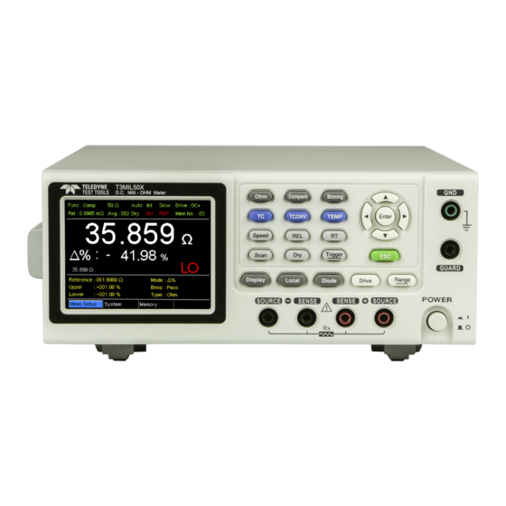
T3MIL Series User Manual Compare Function The compare function compares a measured value to a Background “Reference” value that has an upper (HI) and lower (LO) limit. If the measured value is within the upper and lower limit, then the measured value is judged as IN. There are three compare modes that can be used to make a judgment: ABS, △% and % modes. - Page 39 MEASUREMENT The △% compare function displays the deviation of the measured value from the reference value as a percentage. {[(Measured Value-Reference)/Reference]%}. Compare function Measured value indicator Deviation of the measured value from the reference value as a percentage Pass/Fail judgment Reference, limits, compare mode and beep mode The upper (HI) and lower (LO) limits are set as a...
- Page 40 T3MIL Series User Manual Compare function Measured value indicator Measured value as a percentage of the reference value Pass/Fail judgment Reference, limits, compare mode and beep mode A measured value that falls within the upper and lower limits is considered IN (pass), a value that falls below the lower limits is considered LO, and a value that falls over the upper limit is a HI.
- Page 41 MEASUREMENT Use the arrow keys to navigate to the Reference setting 3. Reference value and press Enter. setting Use the left and right arrow keys to select a digit. Use the up and down arrow keys to edit the value of the selected digit and the unit.
- Page 42 T3MIL Series User Manual Use the arrow keys to navigate to the Beep setting. 5. Beep setting Press Enter to toggle the beep setting. Move Toggle Enter Beep setting Off, Pass, Fail Beep Setting: The Beep setting can also be set from the Note System>Utility>Beep>Compare menu.
-
Page 43: Binning Function
MEASUREMENT Binning Function The Binning function is used to grade DUTs into eight Background different bins according to 8 sets of upper and lower limits. Two compare modes can be used in this function, ABS and △% modes. Binning function Grading results indicator Upper and lower... - Page 44 T3MIL Series User Manual For further details on the ABS or △% compare modes, Note see the description in the Compare section, page 38. Although the 8 bins have their own upper and lower 3. Reference value limits, they still share a common reference value. setting Use the arrow keys to go to the Reference setting and press Enter.
- Page 45 MEASUREMENT The upper limit must be higher than the lower limit. Not Note setting the upper limit higher than the lower limit is not allowed. Likewise the lower limit cannot be set higher than the upper limit. Use the arrow keys to navigate to the Beep setting. 5.
- Page 46 T3MIL Series User Manual The Count display mode tabulates the results on the right-hand side of the display and shows the bin settings on the left. Tabulated result of each bin Overall results Clear results Upper and lower limits of Bin 1~8 To toggle the display mode, go to the Disp setting and press Enter.
-
Page 47: Temperature Measurement
MEASUREMENT Temperature Measurement The temperature measurement function uses a PT-100 Background temperature probe. The measured temperature is displayed on the display. For more information on the PT-100 sensor, see the appendix on page 141. There is only one range for the temperature function. However the resistance measurement range can still be changed when in the temperature function. - Page 48 T3MIL Series User Manual The Ambient temperature setting should be turned off 3. Ambient when using the temperature function. Temperature From the bottom menu go to Meas. Setup > Ambient Temperature and turn the Ambient Temperature setting off. See page 60 for setting details. The temperature sensor uses the rear panel TC Sensor 4.
-
Page 49: Temperature Compensation
MEASUREMENT Temperature Compensation If the resistance of a DUT at a particular temperature is Background needed, the compensation function can be used. This function can simulate the resistance of a DUT at a desired temperature. If the ambient temperature and the temperature coefficient of the DUT are known, it is possible to determine the resistance of a DUT at any temperature. - Page 50 T3MIL Series User Manual The ambient temperature can be either measured with 2. Ambient the PT-100 sensor or be set manually. Temperature If using the PT-100 sensor the Ambient temperature setting should be turned off. If the PT-100 probe is not used, then the ambient temperature needs to be manually set.
- Page 51 MEASUREMENT Sensor Connection: 4. Temperature compensation GPIB connection RS232 HANDLER / SCAN / EXT I/O PT-100 temperature 240V , 50 60Hz 25VA MAX sensor TC SENSOR WARNING TO AVOID SHOCK, REMOVE INPUTS BEFORE OPENING. SER.NO. LABEL If the sensor is not connected, then the Ambient Note temperature needs to be manually set.
-
Page 52: Temperature Conversion
T3MIL Series User Manual Temperature Conversion The Temperature Conversion function allows you to Background determine the temperature change of a DUT at any given resistance, if the initial temperature, the inferred zero resistance temperature for the DUT and the initial resistance of the DUT are known. - Page 53 MEASUREMENT Metallic conductors show increased resistivity when Common inferred temperature is increased, and likewise show reduced zero resistance resistivity when temperature is reduced. Inferred zero temperatures resistance temperature is simply the inferred temperature at which the material will have no resistance. This value is derived from the temperature coefficient of the material.
- Page 54 T3MIL Series User Manual Use the arrows keys to go to Initial Resistance, Initial 2. Initial Resistance, Temperature or Constant (inferred initial resistance Initial Temperature temperature) and press Enter. and Constant settings Use the left and right arrow keys to select a digit and use the up and down arrow keys to edit the digit.
- Page 55 MEASUREMENT DUT connection 4 wire Kelvin: SOURCE SENSE SENSE SOURCE GUARD shielding...
-
Page 56: Measurement Settings
T3MIL Series User Manual Measurement Settings The following measurement settings are used to Background configure the various measurement modes. Average Function The average function smooths measurements using a Background moving average. The average function sets the number of samples used for the moving average; a higher number results in smoother measurement results. -
Page 57: Measure Delay
MEASUREMENT Measure Delay The Measure Delay setting inserts a delay time between Background each measurement. Measure delay is turned off by default. Measurement start with Measure delay time Test signal Measure delay time Default Measurement start time The measure delay setting is useful for measuring components that need some time to charge if the default measurement start time is not adequate. -
Page 58: Trigger Delay
T3MIL Series User Manual Trigger Delay The Trigger Delay setting adds a delay when an external Background trigger signal is recognized. Normally the external trigger is recognized when there is no contact bounce in the signal for a fixed length of time, this time is known as the bounce monitoring window. -
Page 59: Trigger Edge
MEASUREMENT Use the arrow keys to turn Trigger Delay on and set the 2. Trigger Delay delay time. Press Enter to confirm the settings. setting appears Trigger Delay setting Trigger Delay OFF, ON: 0 ~ 1000ms Pressing ESC before pressing ENTER will exit the Trigger Note Delay settings. -
Page 60: Temperature Unit
T3MIL Series User Manual Temperature Unit Temperature units can be set to Fahrenheit or Celsius for Background all temperature measurements. From one of the main screens, press 1. Select Meas. Setup Temperature Unit key so that the menu menu icon setting system at the bottom of the display has focus. -
Page 61: Line Frequency
MEASUREMENT Use the arrow keys to set the Ambient Temperature. 2.Ambient Press Enter to confirm the setting. Temperature setting appears Ambient Temperature Ambient Temperature Off, On: -50ºC ~ 399.9ºC Pressing ESC before pressing ENTER will exit the Ambient Note Temperature setting. Line Frequency The Line Frequency setting selects the appropriate line Background... -
Page 62: Pwm Setting
T3MIL Series User Manual PWM Setting The PWM setting will set the duty of the PWM Drive Background setting. The duty is set with ON and OFF times for the waveform. OFF time time See page 30 for Drive setting details. From one of the main screens, press 1. -
Page 63: System Settings
MEASUREMENT System Settings The System settings are used to view the system Background information, set the power on state, the remote interface, screen brightness, external interface and beep settings as well as access the calibration menu. System Information The System Information will show the manufacturer, Background model, software version and serial number of the unit. -
Page 64: Power On Status Setup
T3MIL Series User Manual Power On Status Setup The Power On Status Setup allows you to either load the Background previous settings or the default settings on startup. From one of the main screens, press 1. Select Power On System Status key so that the menu menu icon... -
Page 65: Brightness
MEASUREMENT Use the arrow keys to choose an interface and to set the 2. Interface setting baud rate (RS232). The EOL (end of line) character can appears also be set. Press Enter to confirm the settings. Interface Interface RS232, Baud Rate (1200, 2400, 4800, 9600, 19200, 38400, 57600, 115200) DATA OUT ON, OFF... -
Page 66: User Define Pins
T3MIL Series User Manual Brightness Brightness 01 (dim) ~ 05 (bright) Pressing ESC before pressing ENTER will exit from the Note Brightness settings. User Define Pins The External I/O User Define Pin settings set the logic Background and the active level for the Define 1 and Define 2 pins on the Handler/Scan/EXT I/O port on the rear panel. -
Page 67: Handler Mode
*The OFF operator sets the Logic as true when Operand1 is true. ** Bin O is defined as outside bin 1~ 8. The Bin logic settings are not available for the T3MIL50. Note Pressing ESC before pressing ENTER will exit from the selected External I/O setting. - Page 68 T3MIL Series User Manual Clear: All result signals (PASS, Fail, High and Low) are Clear example cleared at the falling edge of EOT and the results from the current test are output at the rising edge of the EOT signal. EOT falling EOT rising edge...
-
Page 69: Beep
MEASUREMENT From one of the main screens, press 1. Select External System I/O setting key so that the menu menu icon system at the bottom of the display has focus. Go to System and press Enter. Move Go to Utility and press Enter. Select menu Enter Go to External I/O and press... -
Page 70: High Voltage Protect
The HVP function is enabled by default and can be Note deactivated manually by the user. When HVP is disabled, the user should pay attention if any high voltage occurs from the connected DUT, which may cause damage to the T3MIL50/50X. - Page 71 MEASUREMENT From one of the main screens, press 1. Select High System Voltage Protect key so that the menu menu icon setting system at the bottom of the display has focus. Go to System and press Enter. Move Go to Utility and press Enter. Select menu Enter Go to High Voltage Protect and...
-
Page 72: Handler/Scan Interface
T3MIL Series User Manual ANDLER/SCAN INTERFACE Handler Overview ................73 Pin Definitions for the Handler Interface .......... 75 Handler Interface for Binning and Compare Functions ........75 Scan Overview ..................77 Pin Definitions for the SCAN Interface ..............78 Scan Interface ......................78 Scan Setup ...................... -
Page 73: Handler Overview
HANDLER/SCAN INTERFACE Handler Overview The Handler interface is used to help grade components Background based on the Compare or Binning function test results. The appropriate pins on the handler interface are active when the Compare or Binning function is used. There are 17 TTL outputs and 1 TTL inputs. - Page 74 T3MIL Series User Manual High when the compare result is either FAIL HI or LO (fail). High when the compare result is IN PASS (pass). For the full pin definition, please refer to the table listed below. The output current from all the pins and the VINT(+5V) Note pin cannot exceed 60mA.
-
Page 75: Pin Definitions For The Handler Interface
HANDLER/SCAN INTERFACE Pin Definitions for the Handler Interface As this interface is used for the handler and scan functions, the interface pinout depends on the function mode. The following pinout is only applicable when using the Binning or Compare function. HANDLER / SCAN / EXT I/O Handler Interface for Binning and Compare Functions Name... - Page 76 T3MIL Series User Manual Userdefine2 High or low when the user define2 Compare, logic conditions are met. Binning Userdefine1 High or low when the user define1 Compare, logic conditions are met. Binning VEXT External DC Voltage, acceptable range is +5V. Ready High when the measurement has finished.
-
Page 77: Scan Overview
HANDLER/SCAN INTERFACE Scan Overview The Scan function is used to automatically bin groups of Background up to 100 components. The associated pins in the handler interface are active when the Scan function is activated. There are a total of 6 outputs, 3 inputs as well as a GND and power (+5V) pin. -
Page 78: Pin Definitions For The Scan Interface
T3MIL Series User Manual Pin Definitions for the SCAN Interface As this interface is used for the handler and scan functions, the interface pinout depends on the function mode. The following pinout is only applicable when using the Scan function. HANDLER / SCAN / EXT I/O Scan Interface Name... -
Page 79: Scan Setup
An automated handler or test fixture is required to interface the DUTs to the measurement terminals and the scan interface that controls the timing of each scan. Scan I/O T3MIL50/50X Measurement terminals Source- S+ Source+ Automated Handler/Test Fixture Channel ·····... - Page 80 T3MIL Series User Manual The △% compare function compares the deviation of the measured value from the reference value as a percentage. { [(Measured Value-Reference)/Reference]%}. A measured value that falls within the upper and lower limits is considered IN (pass), a value that falls below the lower limits is considered LO, and a value that falls over the upper limit is a HI.
- Page 81 HANDLER/SCAN INTERFACE Range Abs, △% The Channel setting sets the number of DUT channels 3. Channel setting that are used. Use the arrow keys to navigate to the Channel setting and press Enter. Use the left and right arrow keys to select a digit. Use the up and down arrow keys to edit the value of the selected digit.
- Page 82 T3MIL Series User Manual The results will be displayed on the screen as each test is performed. The results will also be output through the scan port until the scan has finished. Scan function Measured value indicator Pass/Fail judgment Change display view Reference, limits, scan mode, current channel, measurement delay...
-
Page 83: Scan Output
HANDLER/SCAN INTERFACE Scan Output The timing diagrams for the scan output under different Background conditions are shown below. Ready message displayed… After the manual trigger key is pressed…. Relay Relay Pass Pass High High Clock Clock STRB STRB Scan channel 1. Delay time has Scan channel n. -
Page 84: Configure Interface
The RS-232 and USB interfaces are standard for both Overview models. The remote control interfaces allow the T3MIL50/50X to be programmed for automatic testing. For more information on remote control programming, please see the Command Overview chapter on page 92. -
Page 85: Configure Rs-232 Interface
Go to the Windows Device Manager. For Windows 7 go to: Start Menu > Control Panel > Hardware and Sound > Device Manager The T3MIL50/50X will appear as an unknown Virtual Com Port under “Other Devices”. Right-click Other Devices and select “Update Driver Software”. -
Page 86: Rs232/Usb Function Check
Run this query from the terminal. *idn? This should return the Manufacturer, Model number, Serial number, and Firmware version. Teledyne, T3MIL50X, TXXXXXXXX, V1.00 If you are not familiar with using a terminal application to Note send/receive remote commands from the serial port or via a USB connection, please page 87 (Using Realterm to Establish a Remote Connection) for more information. -
Page 87: Using Realterm To Establish A Remote Connection
Download Realterm and install according to the 1. Install Realterm instructions on the Realterm website. Connect the T3MIL50/50X via USB (page 84) or via 2. Configure RS232 (page 85). connection If using RS232, make note of the configured baud rate. - Page 88 *idn? Click on Send ASCII. The terminal display will return the following: Teledyne,T3MIL50X,TXXXXXXXX,V1.00 (manufacturer, model, serial number, version) If Realterm fails to connect to the T3MIL50/50X, please 5. Errors or check all the cables and settings and try again. Problems...
-
Page 89: Save/Recall
The save function saves the current function as well the Background settings related to that function. There are 20 memory slots that can be used to save and recall settings on the T3MIL50/50X. When you are in the desired function mode, press the 1. Enter the Memory menu key (if necessary) to so that the menu system at the bottom of the display has focus. - Page 90 T3MIL Series User Manual The Recall/Save Setup menu will appear. The No. setting should be already highlighted when 2. Save/ entering the Recall/Save Setup menu. If not, use the Recall/Clear Left/Right arrow keys to highlight the No. setting. Memory No. setting Recall, Save, Clear settings Select and Move...
- Page 91 SAVE/RECALL After saving the settings, press ESC to return to the current function mode. After recalling settings, the unit will automatically go to the recalled setting function. Pressing ESC before pressing Enter will exit the Note Save/Recall/Clear operation. Press the Enter key when the No. setting is highlighted to View memory slot see which memory slots are empty.
-
Page 92: Command Overview
T3MIL Series User Manual OMMAND OVERVIEW The Command overview chapter lists all the programming commands in alphabetical order. The command syntax section shows you the basic syntax rules you have to apply when using commands. Command Syntax Partial compatibility Compatible IEEE488.2 Standard Partial compatibility... - Page 93 COMMAND OVERVIEW A query is a simple or compound Query command followed by a question mark (?). A parameter (data) is returned. SENSe:RANGe? Example Commands and queries have two different forms, long Command Forms and short. The command syntax is written with the short form of the command in capitals and the remainder (long form) in lower case.
- Page 94 T3MIL Series User Manual Any of NR1,2,3 1,1.5,4.5e-1 <NRf> ASCII text string TEST_NAME <string> Marks the end of a command line. The following Message messages are in accordance with IEEE488.2 standard. Terminator (EOL) The most common Remote LF, CR, CR+LF, EOL character is Command LF+CR...
-
Page 95: Command List
COMMAND OVERVIEW Command List General Commands SENSe:FUNCtion ....................98 SENSe:AUTo ......................98 SENSe:RANGe ....................... 99 SENSe:SPEed ......................99 SENSe:REL:STATe ....................99 SENSe:REL:DATa ....................100 SENSe:REALtime:STATe ..................100 SENSe:DISPlay ..................... 101 TRIGger:SOURce ....................101 READ ........................101 Compare Commands CALCulate:COMPare:TYPE .................. 102 CALCulate:COMPare:LIMit:REFerence ............... - Page 96 T3MIL Series User Manual Temperature Compensate Commands TEMPerature:COMPensate:CORRect ..............112 TEMPerature:COMPensate:COEFficient ............. 112 Temperature Conversion Commands TEMPerature:CONVersion:RESistance ............... 113 TEMPerature:CONVersion:TEMPerature ............113 TEMPerature:CONVersion:CONStant ..............113 TEMPerature:CONVersion:DISPlay ..............114 TEMPerature:CONVersion:MATH:DATa ............. 114 Temperature Commands TEMPerature:STATe ....................115 TEMPerature:DATa ....................115 Scan Commands CALCulate:SCAN:CHANnel .................
- Page 97 COMMAND OVERVIEW SYSTem:LFRequency .................... 125 SYSTem:PWM:ON ....................126 SYSTem:PWM:OFF ....................126 System Commands *IDN ........................127 SYSTem:SERial ..................... 127 SYSTem:BRIGhtness .................... 127 USERdefine<X>:ACTive ..................127 USERdefine<X>:FIRStdata ................... 128 USERdefine<X>:LOGic ..................128 USERdefine<X>:SEConddata ................129 SYSTem:HANDler ....................129 SYSTem:KEYClick:BEEPer ..................129 SYSTem:VOLTage:PROTect ..................
-
Page 98: General Commands
T3MIL Series User Manual General Commands SENSe:FUNCtion Query Sets or returns the function mode. Description Syntax SENSe:FUNCtion {OHM|COMP|BIN|TC|TCONV|SCAN|DIODE} Query Syntax SENSe:FUNCtion? OHM MODE Parameter/ Return parameter COMP MODE COMP BIN MODE TC MODE TCONV MODE TCONV TEMP MODE* OHM+T* SCAN MODE SCAN DIODE MODE DIODE... -
Page 99: Sense:range
COMMAND OVERVIEW SENSe:RANGe Query Sets or returns the range of the present function. Description Syntax SENSe:RANGe <NRf> Query Syntax SENSe:RANGe? 5E-3~ 5E+6 Parameter <NRf> 5E-3 ~ 5E+6 Return parameter <NR3> Example SENS:RANG 0.005 Sets range to 5mΩ. SENS:RANG? >5.0000E-3 Returns the range as 5mΩ. SENSe:SPEed Query Sets or returns the measurement speed. -
Page 100: Sense:rel:data
T3MIL Series User Manual The SENS:REL:STAT can only be turned ON when Note measured value is displayed. SENSe:REL:DATa Query Sets or returns the relative value for the relative function. Description Syntax SENSe:REL:DATa <NRf> Query Syntax SENSe:REL:DATa? 0.0000~500.00 Parameter <NRf> The unit will be auto set by the present range. -
Page 101: Sense:display
COMMAND OVERVIEW SENSe:DISPlay Query Sets or returns the display mode. There are two display Description modes, normal and simple. Syntax SENSe:DISPlay <NR1> | {OFF|ON} Query Syntax SENSe:DISPlay? 0:OFF. Parameter/ <NR1> 1:ON. Return parameter Display mode is normal. Display mode is simple. Example SENS:DISP OFF Sets the display mode to normal. -
Page 102: Compare Commands
T3MIL Series User Manual Compare Commands CALCulate:COMPare:TYPE Query Sets or returns the compared function. Description Syntax CALCulate:COMPare:TYPE {OHM|TC} Query Syntax CALCulate:COMPare:TYPE? OHM function. Parameter/ Return parameter TC function. Example CALC:COMP:TYPE TC Sets the compare to TC function. CALCulate:COMPare:LIMit:REFerence Query Sets or returns the limit reference value for the compare Description function. -
Page 103: Calculate:compare:limit:lower
COMMAND OVERVIEW Syntax CALCulate:COMPare:LIMit:MODE {ABS|DPER|PER} Query Syntax CALCulate:COMPare:LIMit:MODE? The test results are judged from Parameter/ absolute values. Return parameter The test results are judged from a DPER reference value ± a percentage offset. (delta percentage) The test results are displayed as a percentage of the reference value. -
Page 104: Calculate:compare:percent:lower
T3MIL Series User Manual Syntax CALCulate:COMPare:LIMit:UPPer {<NRf>[,<String>]} Query Syntax CALCulate:COMPare:LIMit:UPPer? 000.0000~999.9999 Parameter <NRf> mohm/ohm/kohm/maohm,unit <String> If unit is not set, the unit will be automatically set by the present range. 000.0000~999.9999E± X Return parameter <NR3> Example CALC:COMP:LIM:UPP 0.123,maohm Sets the upper limit value to 0.123MΩ. CALC:COMP:LIM:UPP? >0.1230E+6 Returns the upper limit as 0.123MΩ. -
Page 105: Calculate:compare:beeper
COMMAND OVERVIEW 000.00~999.99 Parameter <NRf> 000.00~999.99 Return parameter <NR2> Example CALC:COMP:PERC:UPP 90.00 Sets the upper limit percent value to +90.00%. CALC:COMP:PERC:UPP? >90.00 Returns the upper limit as +90.00%. Note This command is only applicable when compare mode is set to DPER or PER for compare function. CALCulate:COMPare:BEEPer Query Sets or returns the compare function beeper mode. - Page 106 T3MIL Series User Manual 0: LO Return parameter <NR1> 1: IN 2: HI Example CALC:COMP:LIM:RES? >2 Indicates that the test result is HI.
-
Page 107: Binning Commands
COMMAND OVERVIEW Binning Commands Binning commands are only applicable to T3MIL50X. BINNing:COUNt:CLEar Query Clear all bin sorting function test result counts. Description Syntax BINNing:COUNt:CLEar Parameter <None> BINNing:COUNt:TOTal Query Returns the total number (count total) of test bin results. Description Query Syntax BINNing:COUNt:TOTal? 0~999999999 Return parameter... -
Page 108: Binning
T3MIL Series User Manual Query Syntax BINNing<X>:COUNt:RESult? Parameter <X> 0~99999999 Return parameter <NR1> Example BINN1:COUN:RES? >100 Indicates that bin1 has a pass count of 100. BINNing<X>:LIMit:LOWer Query Sets or returns the lower limit value (absolute value) for Description the selected bin. Syntax BINNing<X>:LIMit:LOWer {<NRf>[,<String>]} Query Syntax...:Limit:lower -
Page 109: Binning
COMMAND OVERVIEW 000.0000~999.9999E± X Return parameter <NR3> Example BINN1:LIM:UPP 0.95,maohm Sets bin1 upper limit value to 0.95MΩ. BINN1:LIM:UPP? >0.9500E+6 Returns the upper limit as 0.95MΩ. BINNing<X>:PERCent:LOWer Query Sets or returns the lower value percentage value for the Description selected bin. The value is a percentage offset from the reference value.:Percent:lower -
Page 110: Binning:limit:beeper
T3MIL Series User Manual Example BINN1:PERC:UPP 150.95 Sets the bin1 upper limit percent value to +150.95%. BINN1:PERC:UPP? >150.95 Returns the upper limit percentage value as +150.95%. BINNing:LIMit:BEEPer Query Sets or returns beeper mode for the bin sorting function. Description Syntax BINNing:LIMit:BEEPer {OFF|PASS|FAIL} Query Syntax BINNing:LIMit:BEEPer? -
Page 111: Binning:limit:reference
COMMAND OVERVIEW The test results are judged from Parameter/ absolute values. Return parameter The test results are judged from a DPER reference value ± a percentage offset. (delta percent) Example BINN:LIM:MODE DPER Sets the mode to Δ%. BINNing:LIMit:REFerence Query Sets or returns the limit reference value for the bin Description sorting function. -
Page 112: Temperature Compensate Commands
T3MIL Series User Manual Temperature Compensate Commands TEMPerature:COMPensate:CORRect Query Sets or returns the reference temperature for the Description temperature compensation function. Syntax TEMPerature:COMPensate:CORRect <NRf> Query Syntax TEMPerature:COMPensate:CORRect? -50.0~399.9 (Unit: ºC) Parameter <NRf> -50.0~399.9 (Unit: ºC) Return parameter <NR2> Example TEMP:COMP:CORR 25.5 Sets the reference temperature to 25.5ºC. -
Page 113: Temperature Conversion Commands
COMMAND OVERVIEW Temperature Conversion Commands TEMPerature:CONVersion:RESistance Query Sets or returns the initial resistance for the temperature Description conversion function. Syntax TEMPerature:CONVersion:RESistance {<NRf>[,<String>]} Query Syntax TEMPerature:CONVersion:RESistance? 000.0001~999.9999 Parameter <NRf> mohm/ohm/kohm/maohm,unit <String> If the unit is not set, the unit will be automatically set by the present range. -
Page 114: Temperature:conversion:display
T3MIL Series User Manual Syntax TEMPerature:CONVersion:CONStant <NRf> Query Syntax TEMPerature:CONVersion:CONStant? 0.0~999.9 Parameter <NRf> 0.0~999.9 Return parameter <NR2> Example TEMP:CONV:CONS 235 Sets the temperature constant to 235. TEMPerature:CONVersion:DISPlay Query Sets or returns the temperature display mode for the Description temperature conversion function. Syntax TEMPerature:CONVersion:DISPlay <NR1>... -
Page 115: Temperature Commands
COMMAND OVERVIEW Temperature Commands TEMPerature:STATe Query Description Sets or returns the temperature function state. Syntax TEMPerature:STATe {<NR1>|OFF|ON} Query Syntax TEMPerature:STATe? Parameter/ <NR1> 0:OFF Return parameter 1:ON Turn the temp function off. Turn the temp function on. Example TEMP:STAT ON Sets the TEMP (Ohm+T) function on. TEMPerature:DATa Query Returns the PT-100 sensor temperature measurement in... -
Page 116: Scan Commands
T3MIL Series User Manual Scan Commands CALCulate:SCAN:CHANnel Query Sets or returns the channel for the scan function. Description Syntax CALCulate:SCAN:CHANnel <NR1> Query Syntax CALCulate:SCAN:CHANnel? 1~100 Parameter/ <NR1> Return parameter Example CALC:SCAN:CHAN 5 Sets the channel to 5. CALCulate:SCAN:DELay Query Sets or returns the interval delay for the scan function. Description Syntax CALCulate:SCAN:DELay <NR1>... -
Page 117: Calculate:scan:limit:mode
COMMAND OVERVIEW Example CALC:SCAN:LIM:REF 10.00,mohm Sets the reference limit to 10.00mΩ. CALC:SCAN:LIM:REF? >10.0000E-3 Returns the reference limit as 10.00mΩ. CALCulate:SCAN:LIMit:MODE Query Sets or returns the scan function compare mode. Description Syntax CALCulate:SCAN:LIMit:MODE {ABS|DPER} Query Syntax CALCulate:SCAN:LIMit:MODE? The test results are judged from Parameter/ absolute values. -
Page 118: Calculate:scan:limit:upper
T3MIL Series User Manual CALCulate:SCAN:LIMit:UPPer Query Sets or returns upper limit of the scan function. Description Syntax CALCulate:SCAN:LIMit:UPPer {<NRf>[,<String>]} Query Syntax CALCulate:SCAN:LIMit:UPPer? 000.0000~999.9999 Parameter <NRf> mohm/ohm/kohm/maohm,unit <String> If unit is not set, the unit will be automatically set by the present range. 000.0000~999.9999E±... -
Page 119: Measure
COMMAND OVERVIEW Syntax CALCulate:SCAN:PERCent:UPPer <NRf> Query Syntax CALCulate:SCAN:PERCent:UPPer? 000.00~999.99 Parameter <NRf> 000.00~999.99 Return parameter <NR2> Example CALC:SCAN:PERC:UPP 90.00 Sets the upper limit percent value to +90.00%. CALC:SCAN:PERC:UPP? >90.00 Returns the upper limit as +90.00%. MEASure<X> Query Returns the results of the selected channel in the scan Description mode, including HI/LO/IN and value. - Page 120 T3MIL Series User Manual Example SHOW? Returns 1111111111______________________________________ ________________________________________________ _____.
-
Page 121: Source Commands
COMMAND OVERVIEW Source Commands Source commands are only applicable to T3MIL50X. SOURce:DRY Query Sets or returns the dry circuit test mode. Description Syntax SOURce:DRY {<NR1> | {OFF|ON} Query Syntax SOURce:DRY? 0:OFF. Parameter/ <NR1> 1:ON. Return parameter Turn dry circuit test mode off. Turn dry circuit test mode on. -
Page 122: Meas. Setup Commands
T3MIL Series User Manual Meas. Setup Commands SYSTem:AVERage:STATe Query Sets or returns the average function state. Description Syntax SYSTem:AVERage:STATe <NR1> | {OFF|ON} Query Syntax SYSTem:AVERage:STATe? 0:OFF. Parameter/ <NR1> 1:ON. Return parameter Turn the average function off. Turn the average function on. Example SYST:AVER:STAT OFF Turns the average function off. -
Page 123: System:mdelay:data
COMMAND OVERVIEW Turn the measurement delay off. Turn the measurement delay on. Example SYST:MDEL:STAT OFF Turns the measurement delay function off. SYSTem:MDELay:DATa Query Sets or returns the measurement delay time. Description Syntax SYSTem:MDELay:DATa <NRf> Query Syntax SYSTem:MDELay:DATa? 0.000~100.000 Parameter/ <NRf> Unit: ms Return parameter For values under 1s, the unit resolution... -
Page 124: Trigger:edge
T3MIL Series User Manual Syntax TRIGger:DELay:DATa <NR1> Query Syntax TRIGger:DELay:DATa? 0~1000 Parameter/ <NR1> Unit:ms Return parameter Example TRIG:DEL:DAT 100 Sets the trigger delay time to 100ms. TRIGger:EDGE Query Sets or returns the trigger edge (falling or rising edge). Description Syntax TRIGger:EDGE {RISING|FALLING} Query Syntax TRIGger:EDGE? -
Page 125: Temperature:ambient:data
COMMAND OVERVIEW 0:OFF. Parameter/ <NR1> 1:ON. Return parameter Disables the user-set ambient temperature. Enables the user-set ambient temperature. Example TEMP:AMB:STAT OFF Disables the user-set ambient temperature. TEMPerature:AMBient:DATa Query Sets or returns the user-set ambient temperature value for Description the temperature compensation and the temperature conversion function. -
Page 126: System:pwm:on
T3MIL Series User Manual Example SYST:LFR 60 Sets the line frequency to 60Hz. SYST:LFR? >60Hz Returns the line frequency as 60Hz. SYSTem:PWM:ON Query Sets or returns the duty ON period for the PWM drive Description mode. PWM drive mode is only available for the T3MIL50X. Note Syntax SYSTem:PWM:ON <NR1>... -
Page 127: System Commands
Query Returns the manufacturer, model No., serial number and Description system version number. Query Syntax *IDN? Return parameter <String> 31 characters Example *IDN? >Teledyne,T3MIL50X,TXXXXXXXX,V1.00. SYSTem:SERial Query Returns the serial number. Description Query Syntax SYSTem:SERial? 9 characters Return parameter <String> Example SYST:SER? >... -
Page 128: Userdefine
T3MIL Series User Manual Syntax USERdefine<X>:ACTive <NR1> Query Syntax USERdefine<X>:ACTive? Userdefine pin 1~2 Parameter/ <X> Return parameter 1:active low state <NR1> 2:active high state Example USER1:ACT 1 Sets the userdefine1 pin IO to active low state. USERdefine<X>:FIRStdata Query Sets or returns the first operand for the selected user Description define pin.:Firstdata -
Page 129: Userdefine
COMMAND OVERVIEW USERdefine<X>:SEConddata Query Sets or returns the second operand for the selected user Description define pin. Syntax USERdefine<X>:SECondata <NR1> Query Syntax USERdefine<X>:SECondata? Parameter/ <X> Return parameter 1~8:bin1~bin8 state <NR1> 9:bin out state 10:hi state 11:low state 12:pass state 13:fail state Example USER1:SEC 3 Sets the last operand of userdefine1 as the state of the...:Seconddata -
Page 130: System:voltage:protect
T3MIL Series User Manual 0:OFF. Parameter/ <NR1> 1:ON. Return parameter Turn the keyclick beeper off. Turn the keyclick beeper on. Example SYST:KEYC:BEEP OFF Sets the keyclick beeper off. SYSTem:VOLTage:PROTect Query Sets or returns the HVP function state. Description Syntax SYSTem:VOLTage:PROTect <NR1> | {OFF | ON} Query Syntax SYSTem:VOLTage:PROTect? 0: OFF. -
Page 131: System:version
COMMAND OVERVIEW Syntax SYSTem:LOCal Parameter <None> SYSTem:VERSion Query Returns the SCPI version of the device. Description Query Syntax SYSTem:VERSion? 10 characters Return parameter <String> Example SYST:VERS? >SCPI1994.0. SCPI version: 1994... -
Page 132: Memory Commands
T3MIL Series User Manual Memory Commands MEMory:SAVe Query Saves the settings to the selected memory slot. Description Syntax MEMory:SAVe <NR1> 1~20 Parameter <NR1> Example MEM:SAV 1 Saves the settings to memory slot 1. MEMory:RECall Query Recalls the settings from the selected memory slot. Description Syntax MEMory:RECall <NR1>... - Page 133 COMMAND OVERVIEW Example MEM:STAT? > NFFNN-NNNNN-NNNNN-NNNNN Indicates that memory slots 2 and 3 have data and that all other memory slots are empty.
-
Page 134: Status Commands
T3MIL Series User Manual Status Commands STATus:PRESet Query Sets the QUESTionable enable register to zero. Description Syntax STATus:PRESet <NONE> Parameter <None> STATus:QUEStionable:ENABle Query Sets or returns the Questionable Data Enable register. Description Syntax STATus:QUEStionable:ENABle <NR1> Query Syntax STATus:QUEStionable:ENABle? 0~32767. Parameter/ <NR1>... -
Page 135: Ieee 488.2 Common Commands
COMMAND OVERVIEW IEEE 488.2 Common Commands *CLS Query Clears the Event Status register (Output Queue, Description Operation Event Status, Questionable Event Status, Standard Event Status). Syntax *CLS Parameter <None> *ESE Query Sets or returns the ESER (Event Status Enable Register) Description contents. -
Page 136: Opc
T3MIL Series User Manual *OPC Query Sets or returns the operation complete bit (bit0) in SERS Description (Standard Event Status Register) when all pending operations are completed. Syntax *OPC Query Syntax *OPC? Parameter <None> Return parameter <NR1> 0:operation not complete 1:operation complete Example *OPC? -
Page 137: Stb
COMMAND OVERVIEW *STB Query Returns the SBR (Status Byte Register) contents. Description Query Syntax *STB? Return parameter <NR1> 0~255 Example *STB? >81 SESR=01010001 *TRG Query Manually triggers the instrument. Description Syntax *TRG Parameter <None>... -
Page 138: Status System
T3MIL Series User Manual Status system The diagram below is a description of the status system. Questionable Data Status Register Event Enable Voltage Overload Not Used Not Used Not Used Output Not Used Buffer Temp Overload Not Used Not Used Not Used Ohms Overload Not Used... -
Page 139: Faq
● What are the different measurement speeds? ● The T3MIL50/50X performance does not match the specifications. What are the different measurement speeds? There are two measurement speeds for both resistance and temperature measurement. At the slow measurement rate, the measurement speed is 10 samples/s and at the fast measurement rate the measurement speed is at 60 samples/s. -
Page 140: Appendix
T3MIL Series User Manual PPENDIX Function Selection Combinations ............ 141 Function Combination Table ................141 Temperature Measurement .............. 142 Reference Temperature Table ................142 RTD Sensors ......................143 Optional Platinum Sensor ................... 143 Specifications ..................145 Resistance Measurement ..................145 Dry Resistance Measurement ................ -
Page 141: Function Selection Combinations
APPENDIX Function Selection Combinations Function Combination Table The following table shows which functions can be used Overview with the Relative, Drive and Dry Circuit functions. Function Dry( Drive( ✔ ✔ ✔ Comp ✔ ✔ ✔ ✔ ✔ ✔ ✔ ✔ ✔... -
Page 142: Temperature Measurement
T3MIL Series User Manual Temperature Measurement Reference Temperature Table The International Temperature Scale (ITS) is based on the Overview following table. The table has 17 fixed calibration points Background as of 1990. Temperature Element Type ˚K ˚C Hydrogen Triple point 13.8033 -259.3467 (Ne) -
Page 143: Rtd Sensors
APPENDIX RTD Sensors Resistive Thermal Devices (RTDs) are commonly used as Overview temperature sensors. RTDs change resistance linearly over a specific range of temperature. The table below shows some of the inherent features of RTDs compared to thermocouples. Feature Description Accuracy Higher accuracy Resolution... - Page 144 T3MIL Series User Manual Ω@0˚C Type Standard Alpha Beta Delta PT-100 ITS90 0.003850 0.10863 1.49990 100Ω Example—Calculating the resistance of a PT-100 Temperature Calculation Example RTD at 100˚C (T). The following R Ω at 0˚C), alpha, beta, and delta values are used for the PT-100 RTD: T=100˚C Ω...
-
Page 145: Specifications
±(0.05%+0.008%) ~6.25V T3MIL50X Only 5MΩ 100Ω 1μA ±(0.5%+0.008%) ~6.25V T3MIL50 Only 5MΩ 100Ω 1μA ±(0.2%+0.008%) ~6.25V *When use 5mΩ range, in order to obtain a stable value, it is recommended to use 10 times average and fixed connection method such as lock. -
Page 146: Dry Resistance Measurement
T3MIL Series User Manual lead to the panel due to the different temperature between internal and external parts of the instrument. Therefore, please wait 1 minute in order to obtain an accurate value after the test leads have been connected or disconnected. -
Page 147: Interface
Signal: LOW, HIGH, FAIL, PASS, EOT, READY, BIN 1~8, BIN OUT: total 15 TTL outputs. Scan* Signal: RELAY, PASS, LOW, HIGH, CLOCK, STRB total 6 TTL outputs. Communication T3MIL50: USB/RS-232 Interfaces T3MIL50X: USB/RS-232/GPIB *The Scan and Handler interface use the same connector. Environmental Operation Indoor use, altitude up to 2000m. -
Page 148: Dimensions
T3MIL Series User Manual Dimensions Compare Binning TCONV TEMP Enter Speed Scan Trigger GUARD Display Local Diode Drive Range POWER SOURCE SENSE SENSE SOURCE 275.5 214.0 282.9 222.8... -
Page 149: Certifications
CERTIFICATIONS ERTIFICATIONS Teledyne LeCroy certifies compliance to the following standards as of the time of publication. Please see the EC Declaration of Conformity document shipped with your product for current certifications. EMC Compliance EC DECLARATION OF CONFORMITY - EMC The instrument meets intent of EC Directive 2014/30/EU for Electromagnetic Compatibility. - Page 150 Performance Criteria “C” applied for 70%/25 cycle voltage dips and for 0%/250 cycle voltage interruption test levels per EN61000-4-11. European Contact:* Teledyne GmbH, European Division Im Breitspiel 11c D-69126 Heidelberg Germany Tel: + 49 6221 82700 AUSTRALIA &...
-
Page 151: Safety Compliance
The instrument is subject to disposal and recycling regulations that vary by country and region. Many countries prohibit the disposal of waste electronic equipment in standard waste receptacles. For more information about proper disposal and recycling of your Teledyne LeCroy product, please visit teledynelecroy.com/recycle. -
Page 152: Restriction Of Hazardous Substances (Rohs)
T3MIL Series User Manual RESTRICTION OF HAZARDOUS SUBSTANCES (RoHS) EC DECLARATION OF CONFORMITY – RoHS Unless otherwise specified, all the materials and processes are compliant with RoHS Directive 2011/65/EU in its entirety, inclusive of any further amendments or modifications of said Directive. - Page 153 CERTIFICATIONS CHINA RoHS 2 Unless otherwise specified, all the materials and processes are compliant with the latest requirements of China RoHS 2. The hazardous substances contained in the instrument are disclosed in accordance with the standards SJ/T 11364-2014 (Marking for the restricted use of hazardous substances in electronic and electrical products) and GB/T 26572-2011 (Requirements on concentration limits for certain restricted substances in electrical and electronic products).
- Page 154 T3MIL Series User Manual Toxic or Hazardous Substances and Elements Lead Mercury Cadmium Hexavalent Polybrominated Polybrominated Part Name (Pb) (Hg) (Cd) Chromium Biphenyls Diphenyl Ethers (Cr6+) (PBB) (PBDE) PCBAs Mechanical Hardware Sheet Metal Plastic Parts Cable Assemblies Display Power Supply Fans Batteries Power Cord...
- Page 155 © 2020 Teledyne Test Tools is a brand and trademark of Teledyne LeCroy Inc. All rights reserved. Specifications,prices,availability and delivery subject to change without notice. Product brand or brand names are trademarks or requested trademarks of their respective holders.