
Related Manuals for Teledyne T3PM1100


Summary of Contents for Teledyne T3PM1100
- Page 1 T3PM1100 Digital Power Meter User Manual GlobalTestSupply www. .com Find Quality Products Online at: sales@GlobalTestSupply.com...
- Page 2 Teledyne LeCroy company. The information in this manual was correct at the time of printing. However, Teledyne LeCroy continues to improve products and reserves the rights to change specification, equipment, and maintenance procedures at any time without notice.
-
Page 3: Table Of Contents
TABLE OF CONTENTS Table of Contents SAFETY INSTRUCTIONS ..........5 GETTING STARTED ............9 Characteristics ............10 Appearance ..............13 Set Up ............... 22 BASIC SETTING ............. 25 Setting up measurement range ........26 Setting up measurement status ......... 30 Setting up System status ........... - Page 4 T3PM1100 User Manual Power measurement ..........214 Introduction to IEC-62301 ........216 EUP Directive Lot6 specifications ......217 Connection Guide ............ 218 CERTIFICATIONS ............221 EMC Compliance ............. 221 Safety Compliance ........... 223 Environmental Compliance ........224 RESTRICTION OF HAZARDOUS SUBSTANCES (RoHS) ..............
-
Page 5: Safety Instructions
Warning: Identifies conditions or practices that WARNING could result in injury or loss of life. Caution: Identifies conditions or practices that CAUTION could result in damage to the T3PM1100 or to other properties. DANGER High Voltage Attention Refer to the Manual Protective Conductor Terminal... - Page 6 T3PM1100 User Manual Safety Guidelines Make sure that the voltage input level does not General Guideline exceed AC600V. CAUTION Make sure the current input level does not exceed 20A. Do not place any heavy object on the ...
- Page 7 SAFETY INSTRUCTIONS (Note) EN 61010-1:2010 specifies the measurement categories and their requirements as follows. The T3PM1100 falls under category II 600V. Measurement category IV is for measurement performed at the source of low-voltage installation. Measurement category III is for measurement performed in the building installation.
- Page 8 T3PM1100 User Manual (Note) EN 61010-1:2010 specifies the pollution degrees and their requirements as follows. The T3PM1100 falls under degree 2. Pollution refers to “addition of foreign matter, solid, liquid, or gaseous (ionized gases), that may produce a reduction of dielectric strength or surface resistivity”.
-
Page 9: Getting Started
Front Panel ................13 Main Display Overview ............. 16 Rear Panel ................. 19 Set Up ............... 22 Tilting the Stand ............... 22 Power Up ................... 23 Connect the wires to the T3PM1100 ........24 GlobalTestSupply www. .com Find Quality Products Online at: sales@GlobalTestSupply.com... -
Page 10: Characteristics
T3PM1100 User Manual Characteristics The T3PM1100 is a high-precision, programmable power meter for measuring low power devices such as switching power supplies, transformers, power supplies, and adapters. It is equipped with a color TFT-LCD screen and also multiple graph displays which are very convenient for reading the measurement results. - Page 11 GETTING STARTED log and screenshot. Auto range function for integration measurement. Full five-digit measurement. Features Voltage measurement range: 15V ~ 600V or automatic switching Current measurement range: 5mA ~ 20A or automatic switching Maximum accuracy of 0.1% of reading + 0.05% ...
-
Page 12: Accessories
T3PM1100 User Manual Accessories Standard Accessories Power Cords x 3 Test leads: 1x red, 1x black Test leads: 1x yellow, 1x blue Package Contents Check the contents before using the instrument. Opening the box Main unit Power cords x 3 Contents ... -
Page 13: Appearance
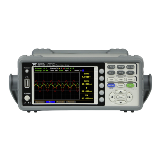
GETTING STARTED Appearance Front Panel Hardcopy Key LCD Display Function Keys V-Range I-Range MAX Hold Hardcopy Mode Setup Hold INTEGRATOR Start Stop Reset Key Lock Trigger Local : Long Push POWER Enter Soft Enter Arrow Trigger Power USB Host keys Keys Port POWER Turns On... - Page 14 T3PM1100 User Manual V-Range key, up/down arrow keys Function Keys V-Range and Enter key can be used together to select a voltage range or auto range measurement mode. Also, Enter press and hold the V-Range key to toggle between manual and auto range setting.
- Page 15 GETTING STARTED Press this key to toggle to key lock. In Key Lock Remote control mode, press this button Local to switch to local mode. See page 77. This button is used to enter the menu, Enter Key Enter confirm the settings and switch between the standard display mode and simple display mode (no function table and display icon).
-
Page 16: Main Display Overview
T3PM1100 User Manual Main Display Overview Max. Hold Sync Voltage Range Mode Remote Source External Update Rate Average Display Hold Current Range CT SF Peak Voltage Peak Current Line Filter Harmonic Calculation Main Measurement Measure Display Storage Key Lock Minor... - Page 17 GETTING STARTED External voltage magnification VT Ratio State (On/Off) External current magnification CT Ratio State (On/Off) External power magnification Power Ratio (On/Off) State Remote control mode (On/Off) Remote Voltage and current filters (On/Off) Line Filter Frequency filters (On/Off) Frequency Filter MAX Hold Retain and display the maximum Maximum Hold...
- Page 18 T3PM1100 User Manual Display the measurement result of 2 major and 8 Standard Display Mode minor measurement parameters Display the measurement result of 4 major Simple Display Mode measurement parameters Secondary menus Display secondary function menu To navigate the secondary function menu, use left and right arrow keys alternately.
-
Page 19: Rear Panel
GETTING STARTED Rear Panel External Voltage RS-232 USB Device Current Input Input 1/2 Input Connector Port Port CURRENT VOLTAGE EXT1 RS232 10V MAX EXT2 240V 50 / 60Hz 2V MAX 20A MAX 600V MAX 30VA MAX CAT II 600V GPIB TO AVOID SHOCK, WARNING REMOVE INPUTS... - Page 20 The maximum measurable current and voltage are 600 V and 20A for voltage and current terminals of the rear panel of the T3PM1100. Do not input exceeded voltage and current, otherwise it will burn the device. ...
- Page 21 GETTING STARTED Do not use this device if the removable cover is removed or loosened. Do not connect any cables and terminals before performing self-test. Use only the power adapter supplied by the manufacturer to avoid accidental injury. Do not use this device for life support systems or ...
-
Page 22: Set Up
T3PM1100 User Manual Set Up Tilting the Stand Pull out the handle sideways and rotate it clockwise for the several applications listed below. Horizontal Tilt Place the unit horizontally. Rotate the handle for tilt stand. Vertical Place the handle vertically for hand carry. -
Page 23: Power Up
GETTING STARTED Power Up 1. Ensure the AC voltage is 100~ 240V. Steps 2. Connect the power cord to the AC voltage input. Make sure the ground connector on the power Note cord is connected to a safety ground. This will influence the measurement accuracy. -
Page 24: Connect The Wires To The T3Pm1100
T3PM1100 User Manual Connect the wires to the T3PM1100 Two separate wires are used to connect the Background T3PM1100, so voltage and current measurement are isolated and don’t interfere with each other. Connection CURRENT VOLTAGE EXT1 diagram 10V MAX EXT2... -
Page 25: Basic Setting
BASIC SETTING ASIC SETTING Setting up measurement range ........26 Auto Range ................28 Setting up measurement status ......... 30 Setting up synchronization source ........... 30 Setting up line filter ..............31 Setting up frequency filter ............32 Setting up crest factor .............. 33 Setting up auto-zero function........... -
Page 26: Setting Up Measurement Range
T3PM1100 User Manual Setting up measurement range To get accurate measurement results, set an appropriate measurement range before performing measurements. Set voltage range 1. Press V-Range button. The V- V-Range Range field turns to bluish. 2. Use up and down arrow keys to select the desired range. - Page 27 BASIC SETTING 2. Use up and down arrow keys to select the desired range. 3. Press Enter button to confirm your Enter selection. Available range Crest Factor AUTO, 5mA, 10mA, 20mA, 50mA, is 3: 100mA, 200mA, 0.5A, 1A, 2A, 5A, 10A, Crest Factor AUTO, 2.5mA, 5mA, 10mA, 25mA, is 6/6A:...
-
Page 28: Auto Range
T3PM1100 User Manual The P.V status icon lights in red when the voltage Note measurement circuit detects that the measured value exceeds setting range by 3 folds (CF is set to 3) or 6 folds (CF is set to 6/6A). - Page 29 BASIC SETTING Example To begin, the measured Irms value is within the current range of I-Auto 20mA. The measured Irms (27.194mA) exceeds the I- Auto 20mA by 130%, so the range is shifted up to 50mA automatically. The measured Irms (3.9994mA) is less than 30% of the I-Auto 20mA, so the range is shifted down to 10mA automatically.
-
Page 30: Setting Up Measurement Status
T3PM1100 User Manual Setting up measurement status Setting up synchronization source 1. Press Setup button. Steps Setup 2. Press Enter button. Enter 3. Press down arrow key to move cursor to the Sync Source field. 4. Use soft keys to select and confirm the desired option. -
Page 31: Setting Up Line Filter
BASIC SETTING Setting up line filter 1. Press Setup button. Steps Setup 2. Press Enter button. Enter 3. Press down arrow key to move cursor to the Line Filter field. 4. Use soft keys to select and confirm the desired option. Option Turn on the line filter function, which is inserted into voltage and current... -
Page 32: Setting Up Frequency Filter
T3PM1100 User Manual Setting up frequency filter 1. Press Setup button. Steps Setup 2. Press Enter button. Enter 3. Press down arrow key to move cursor to the Frequency Filter field. 4. Use soft keys to select and confirm the desired option. -
Page 33: Setting Up Crest Factor
BASIC SETTING Setting up crest factor 1. Press Setup button. Steps Setup 2. Press Enter button. Enter 3. Press down arrow key to move cursor to the Crest Factor field. 4. Use soft keys to select and confirm the desired option. Option Crest Factor is 3. -
Page 34: Setting Up Auto-Zero Function
T3PM1100 User Manual Setting up auto-zero function 1. Press Setup button. Steps Setup 2. Press Enter button. Enter 3. Press down arrow key to move cursor to the Auto Zero field. 4. Use soft keys to select and confirm the desired option. -
Page 35: Setting Up Method Of Calculating Harmonics
BASIC SETTING Setting up method of calculating harmonics 1. Press Setup button. Steps Setup 2. Press Enter button. Enter 3. Press down arrow key to move cursor to the Harmonics field. 4. Use soft keys to select and confirm the desired option. Option Calculate the ratio of harmonic quantity of the 2nd through the upper limit 50th... - Page 36 T3PM1100 User Manual 5. Press right arrow key to move Steps cursor to Order field. Enter 6. Use soft keys to increase or decrease the order number. Option 1-50 Set the upper limit of measured harmonic order within the range from 1 to 50.
-
Page 37: Setting Up Data Update Rate
BASIC SETTING Setting up data update rate 1. Press Setup button. Steps Setup 2. Press Enter button. Enter 3. Press down arrow key to move cursor to the Data Update Rate field. 4. Use soft keys to select and confirm the desired option. - Page 38 T3PM1100 User Manual 6. Use soft keys to select and confirm the desired option. Option 1s/5s/ Time Out period acts like the time limit 10s/20s for detecting a period of the input waveform. Default value Time Out function is only available when Auto is Note selected for Data Update Rate.
-
Page 39: Setting Up Measure Storage
BASIC SETTING Setting up measure storage 1. Press Setup button. Steps Setup 2. Press Enter button. Enter 3. Press down arrow key to move cursor to the Measure Storage field. Measure Storage function is Not available when Note Auto is selected for Data Update Rate. 4. - Page 40 T3PM1100 User Manual 6. Use soft keys to increase or decrease the interval. Option The setting range for Interval is from 00:00:00 to 99:59:59. Default value 00:00:00 When it is set 00:00:00, the interval for measure Note storage will be synchronized with the designated Data Update Rate.
-
Page 41: Setting Up Average Function
BASIC SETTING Setting up average function 1. Press Setup button. Steps Setup 2. Press Average soft key. 3. Press Enter button. Enter 4. Press down arrow key to move cursor to the State field. 5. Use soft keys to select and confirm the desired option. - Page 42 T3PM1100 User Manual 7. Use soft keys to select and confirm the desired option. Option Linear With the designated linear count, it is used to compute linear averages. Exponent With the specified attenuation count, numeric data will be averaged exponentially.
-
Page 43: Setting Up The Voltage And Current Skipping Configuration
BASIC SETTING Setting up the voltage and current skipping configuration 1. Press Setup button. Steps Setup 2. Press V / I Range soft key. 3. Press Enter button. Enter 4. Press down arrow key to move cursor to the Mode field. 5. - Page 44 T3PM1100 User Manual 7. Use soft keys to select and confirm the desired option. Option It is able is skip certain measurement range(s) that are not used by turning on this feature. It can reduce measured data loss which happens while ranges are switched.
- Page 45 BASIC SETTING Default option 10. Press down arrow key to move Steps cursor to Peak Over field for V- Range and I-Range, respectively. 11. Use soft keys to select and confirm the desired option. Press the More soft key to toggle among pages for Peak Over of V-Range and I-Range.
-
Page 46: Setting Up The Skipping Configuration For External
T3PM1100 User Manual The available options for Peak Over field are Note limited within the selected options from the V- Range and I-Range sections above. Setting up the skipping configuration for external 1. Press Setup button. Steps Setup 2. Press V / I Range soft key. - Page 47 BASIC SETTING 6. Press ESC button. Steps 7. Press External soft key. 8. Press Enter button. Enter 9. Press down arrow key to move cursor to each field of either External Sensor 1 or External Sensor 2. 10. Use soft keys to enable or disable the skipping function for each range.
- Page 48 T3PM1100 User Manual 12. Use soft keys to select and confirm desired option. Press More soft key to toggle among pages for Peak Over of Ext-1 and Ext-2, respectively. Option When the occurrence of peak over-range happens in Auto range mode for external input, user is able to define a measurement range to switch to.
-
Page 49: Setting Up The Vt Ratio State
BASIC SETTING Setting up the VT ratio state 1. Press Setup button. Steps Setup 2. Press Ratio soft key. 3. Press Enter button. Enter 4. Press down arrow key to move cursor to the VT Ratio State field. 5. Use soft keys to select and confirm the desired option. -
Page 50: Setting Up The Ct Ratio State
T3PM1100 User Manual 7. Use soft keys to increase or decrease coefficient of VT ratio. Option The setting range for VT Ratio is from 0000.001 to 9999.999. Default value 0001.000 Setting up the CT ratio state 1. Press Setup button. - Page 51 BASIC SETTING 5. Use soft keys to select and confirm the desired option. Option Turn on the CT (Current Transformer) ratio calculation function and the CT status icon on the display lights up in green. Turn off the CT ratio calculation function. Default option 6.
-
Page 52: Setting Up The Power Ratio State
T3PM1100 User Manual Setting up the power ratio state 1. Press Setup button. Steps Setup 2. Press Ratio soft key. 3. Press Enter button. Enter 4. Press down arrow key to move cursor to the Power Ratio State field. 5. Use soft keys to select and confirm the desired option. -
Page 53: Setting Up The External Sensor Input Terminal
BASIC SETTING 7. Use soft keys to increase or decrease coefficient of power ratio. Option The setting range for power ratio is from 0000.001 to 9999.999. Default value 0001.000 Setting up the external sensor input terminal 1. Press Setup button. Steps Setup 2. - Page 54 T3PM1100 User Manual 5. Use soft keys to select and confirm the desired option. Option Ext1 Turn on the Ext1 terminal function that receives voltage up to 10V including shunts and clamps from external output current sensor for measurement and the EXT1 status icon on the display lights up in green.
-
Page 55: Saving And Loading The Setup Parameters
BASIC SETTING 7. Use soft keys to increase or decrease the conversion ratio of either Ext1 or Ext2. Option The setting range for both Ext1 and Ext2 is from 0000.001 to 9999.999. Default value Ext1 0001.000 Ext2 0010.000 In order to enable range skipping configuration for Note external (page 46), it is required to enable external input function first. - Page 56 T3PM1100 User Manual 6. Use soft keys to select and confirm the desired action. Option Save Select Save to store setup parameters into the internal memory. Load Select Load to recall setup parameters back from the internal memory. Default option Save 7.
-
Page 57: Setting Up The Hardcopy And Log Configuration
BASIC SETTING Option 1 - 4 There are 4 sets of internal memories for saving and loading setup parameters. The State field below indicates the status of selected memory set. Free represents the set is empty without saved parameters, whereas Saved indicates the set has been stored with setup parameters. - Page 58 T3PM1100 User Manual Option Capture Select Capture to save screenshot file into the inserted USB disk. The file name ranges from SCREEN00.BMP to SCREEN99.BMP. Select Log to save data log file into the inserted USB disk. The file name ranges from DATA000.CSV to DATA999.CSV...
-
Page 59: Setting Up The Math Configuration
BASIC SETTING a new one with the latest file name will be created. However, for example, when both SCREEN00.BMP and SCREEN02.BMP exist, a new file named SCREEN01.BMP will be saved since system fills filename vacancy automatically. Also, when saved files are full in USB disk, e.g., from SCREEN00.BMP to SCREEN99.BMP, a warning message will be shown and save action will be Not available. - Page 60 ÷B), which are based on the four elementary functions (addition, subtraction, multiplication and division), can be executed by T3PM1100 with 2 select items out of 5 variables (V, I, P, VA, VAR). The result of computation will be a value without units.
- Page 61 BASIC SETTING 10. Use soft keys to select and confirm the desired option. Option Voltage Current Active power Apparent power Reactive power Default option GlobalTestSupply www. .com Find Quality Products Online at: sales@GlobalTestSupply.com...
-
Page 62: Setting Up System Status
T3PM1100 User Manual Setting up System status System information screen 1. Use left and right arrow keys on Steps the front panel to select System function key. 2. Press Enter button to Enter Enter SYSTEM INFORMATION screen where detailed information... -
Page 63: System Configuration Screen
BASIC SETTING 5. Use soft keys along with left and right arrow keys to input the password followed by pressing Enter button twice to enter the Calibration page. Enter Default option 99999 Refer to qualified technician and service manual for Note the calibration procedure. -
Page 64: Setting Up Power On Status
T3PM1100 User Manual Setting up power on status Continue the following setting from SYSTEM Background CONFIG setting screen 1. Press Enter button. Steps Enter 2. Press down arrow key to move cursor to Power On Status Setup field. 3. Use soft keys to select and confirm the desired option. -
Page 65: Setting Up Brightness
BASIC SETTING Setting up brightness Continue the following setting from SYSTEM Background CONFIG setting screen 1. Press Enter button. Steps Enter 2. Press down arrow key to move cursor to Brightness field. 3. Use soft keys to increase or decrease the brightness level Option 1 - 10 The display is the darkest when set to... -
Page 66: Setting Up Key Sound
T3PM1100 User Manual Setting up key sound Continue the following setting from SYSTEM Background CONFIG setting screen 1. Press Enter button. Steps Enter 2. Press down arrow key to move cursor to Key Sound field. 3. Use soft keys to select and confirm the desired option. -
Page 67: Setting Up Remote Interface
BASIC SETTING Setting up remote interface Continue the following setting from SYSTEM Background CONFIG setting screen 1. Press Enter button. Steps Enter 2. Press down arrow key to move cursor to I/O Model field. 3. Use soft keys to select and confirm the desired option. - Page 68 T3PM1100 User Manual For details about configuring USB interface, please see page 109. If interface is set to LAN, the IP model is can be selected from “Manual” and “DHCP”. For details about configuring LAN interface, please see page 112.
-
Page 69: Setting Up Scpi Identity
BASIC SETTING Setting up SCPI identity Continue the following setting from SYSTEM Background CONFIG setting screen 1. Press SCPI soft key to enter SCPI Steps setting screen. 2. Press Enter button. Enter 3. Press down arrow key to move cursor to Type field. 4. -
Page 70: Measurement And Other Functions
T3PM1100 User Manual EASUREMENT AND OTHER FUNCTIONS Measurement function ..........71 Introduction to measurement parameters ......71 Setting measurement parameters ........... 72 Changing the standard and simple display modes ....74 Other functions ............76 Introduction to other functions..........76 Integration measurement function ...... -
Page 71: Measurement Function
MEASUREMENT AND OTHER FUNCTIONS Measurement function The T3PM1100 provides a wide range of basic electricity and power measurement functions. It is equipped with measurement parameters for accurately measuring the voltage, current, power, DC/AC/AC + DC/V-MEAN, power factor, harmonics, frequency, etc. The input impedance of the device is 2MΩ, the maximum input voltage is 600Vrms. -
Page 72: Setting Measurement Parameters
T3PM1100 User Manual Reactive power Power Factor Phase Angle Frequency IHz, VHz Voltage Peak V+pk, V-pk Current Peak I+pk, I-pk Active Power Peak P+pk, P-pk Total Harmonic Distortion THDI, THDV Crest factor CFV, CFI Mathematical Computation MATH Maximum Current Ratio... - Page 73 MEASUREMENT AND OTHER FUNCTIONS 2. Press Enter button. The 1st Enter measurement parameter will be highlighted in green. 3. Press up, down, left and right arrow keys to select other desired measurement parameter. 4. Press Enter button followed by using up and down arrow keys to switch display options for the selected measurement parameter.
-
Page 74: Changing The Standard And Simple Display Modes
T3PM1100 User Manual same process for each measurement parameter. There are up to 2 major and 8 minor measurement parameters to be switched. Changing the standard and simple display modes 1. In the standard display mode, use Steps left and right arrow keys on the front panel to select Enlarge function key. - Page 75 MEASUREMENT AND OTHER FUNCTIONS 3. Press ESC button to return back to original display mode. GlobalTestSupply www. .com Find Quality Products Online at: sales@GlobalTestSupply.com...
-
Page 76: Other Functions
T3PM1100 User Manual Other functions Introduction to other functions Mode Max. Hold KeyLock Display Hold Function name Button Description When the MAX Hold button is pressed, MAX Hold MAX Hold the MAX Hold status icon will light in red in the LCD display to indicate that this function is activated. - Page 77 MEASUREMENT AND OTHER FUNCTIONS V-pk, I+pk, I-pk, P+pk, and P-pk. This button is used to select function or Enter confirm selection. Enter When the Hold button is pressed, the Hold Hold Hold status icon will light in red in the LCD display to indicate that this function is activated.
- Page 78 T3PM1100 User Manual Press the Mode button to select Mode measurement mode. There are 4 Mode measurement modes. AC+DC: Displays all the components of measurement signal. DC: Displays the DC part of the measurement signal. AC: Displays the AC part of the ...
-
Page 79: Integration Measurement Function
MEASUREMENT AND OTHER FUNCTIONS Integration measurement function Setting up Integrator measurement 1. Use left and right arrow keys on Steps the front panel to select Integrator function key. 2. Press Enter button to enter the Enter integrator measurement screen. GlobalTestSupply www. - Page 80 T3PM1100 User Manual 3. Press right arrow key to move cursor to Set key. Enter 4. Press Enter button to enter Select integrator Enter integrator measurement setting measurement mode screen. 5. Press Enter button to enter Mode Enter field. Use up and down arrow keys to toggle between Manual, Standard and Continuous mode.
- Page 81 MEASUREMENT AND OTHER FUNCTIONS If you select Standard or Continuous mode, you need to set integrator measurement time before using integrator function. It can be set from 1 second to 9999 hours, 59 minutes and 59 seconds. When the Set Time is zero, neither Standard mode Note nor Continuous mode can be executed.
- Page 82 T3PM1100 User Manual 7. Press Enter button to enter Enter Function field. Use up and down arrow keys to toggle between Ampere Hours and Watt Hours. Press Enter button again to confirm your selection. Enter If you select Ampere Hours, the measured value in the bottom half section will be displayed in “q”.
- Page 83 MEASUREMENT AND OTHER FUNCTIONS 8. Press down arrow key to move to Select integrator measurement the bottom half section where parameter measured values are displayed. 9. Press Enter button to enter the 1st Enter minor parameter followed by using up and down arrow keys to switch to preferred measurement parameter.
-
Page 84: Introduction To Integrator Parameters
T3PM1100 User Manual Introduction to integrator parameters Parameter name Description Standard Mode It allows user to define a period of Set Time for integrator measurement, which ranges from 1 second to 9999 hours, 59 minutes and 59 seconds. Manual ... - Page 85 MEASUREMENT AND OTHER FUNCTIONS Ampere Hours q: Total mAh q+: Positive total q-: Negative total q(avg): Average current It indicates that elapsed time of integrator Test time measurement. It indicates the time of Set time integrator measurement to be set.
- Page 86 T3PM1100 User Manual Reset The integrator measurement status is cleared. For Watt Hours Measured value parameters Positive total power: WP+ Negative total power: WP- Average power: P(avg) Voltage: Vdc (DC voltage), Vac (AC voltage), Vrms (AC+DC voltage),Vmn (Voltage mean)
-
Page 87: Using The Integrator Function
MEASUREMENT AND OTHER FUNCTIONS Using the integrator function 1. In manual mode, you can directly Manual mode Start press the Start button on the front panel to start integrator function. 2. To stop integration function, press Stop the Stop button on the front panel. GlobalTestSupply www. - Page 88 T3PM1100 User Manual 3. Press the Reset button on the front Reset panel to clear integrator. 1. Set integrator measurement time before using Standard mode integrator function. 2. Other steps are same as running in manual mode. When integrator performing, the test time will increase until the setting integrator measurement time.
- Page 89 MEASUREMENT AND OTHER FUNCTIONS until the Stop button is pressed by the user. In the integration process, select the Measure key Note and press Enter button to return main measurement screen. Select Integrator key and press Enter button to switch back to integration measurement screen.
-
Page 90: Graph Measurement Function
T3PM1100 User Manual Graph measurement function The T3PM1100 provides the professional graph measurement functions by which the user can view fluctuations of measured values in waveform and harmonics in bar and list graphs. It is available, under the graph mode, to adjust both voltage and current ranges in real time and change the display modes along with relevant parameters with ease. - Page 91 MEASUREMENT AND OTHER FUNCTIONS 3. Press right arrow key to move cursor to Set key. Enter 4. Press Enter button to enter Select waveform Enter display mode waveform setting section. 5. Press Enter button to enter Display Enter field. Use up and down arrow keys to toggle between options.
- Page 92 T3PM1100 User Manual Option V, I, P Three items including the measured voltage, current and power are displayed in waveforms of different colors (V: yellow, I: red, Power: green) within the waveform chart. V, I Two items including the measured voltage...
- Page 93 MEASUREMENT AND OTHER FUNCTIONS 7. Press Enter button to enter Time Enter Div field. Use up and down arrow keys to toggle between options. Press Enter button again to confirm your selection. Enter Option 25us, 50us, The diversified time units allow user 100us, 250us, to customize a preferred waveform 500us, 1ms,...
- Page 94 T3PM1100 User Manual 9. Press Enter button to enter Sync Enter field. Use up and down arrow keys to toggle between options. Press Enter button again to confirm your selection. Enter Option Select the voltage of signals as synchronization source.
- Page 95 MEASUREMENT AND OTHER FUNCTIONS 11. Press Enter button to enter Zoom Enter (V) field. Use up and down arrow keys to toggle between options. Press Enter button again to confirm your selection. Enter Option 1, 2, 3 The varied zoom magnifications allow user to customize a preferred waveform graph display.
- Page 96 T3PM1100 User Manual Frequency over When frequency of either voltage or current is limit beyond the limit, which varies per set Time Div, the warning message in the upper-right corner will be shown to alarm user as the figures below.
- Page 97 MEASUREMENT AND OTHER FUNCTIONS Take few examples below that derive from the table above for further descriptions. When Update Time is set 20s, the range of Time Div is from 5ms to 1s and the available Frequency is up to 50Hz. ...
-
Page 98: Setting Up Waveform Graph Parameter
T3PM1100 User Manual Setting up waveform graph parameter 1. Use left and right arrow keys on Steps the front panel to select Graph function key. 2. Press Enter button to enter the Enter Waveform graph display screen. 3. Press right arrow key to move cursor to Parameter key. - Page 99 MEASUREMENT AND OTHER FUNCTIONS 4. Press Enter button to enter Enter parameters setting section. 5. Press Enter button to enter the 1st Enter parameter. Use up and down arrow keys to toggle between options. Press Enter button again to confirm your selection.
- Page 100 T3PM1100 User Manual Option Voltage Vac (AC) Vdc (DC) Vrms (AC+DC) Vmn (V-MEAN) Current Iac (AC) Idc (DC) Irms (AC+DC, V-MEAN) Active Power Apparent Power Reactive power Power Factor Phase Angle Frequency IHz, VHz Voltage Peak V+pk, V-pk Current Peak...
-
Page 101: Setting Up Harmonics Bar Graph Measurement
MEASUREMENT AND OTHER FUNCTIONS Setting up Harmonics bar graph measurement 1. Use left and right arrow keys on Steps the front panel to select Graph function key. 2. Press Enter button to enter the Enter Waveform graph display screen. GlobalTestSupply www. - Page 102 T3PM1100 User Manual 3. Press Enter button to enter Enter Harmonics bar graph display screen where measured values of each harmonic order are shown in the histogram-like bar display. 4. Press right arrow key to move cursor to Set key.
- Page 103 MEASUREMENT AND OTHER FUNCTIONS 6. Press Enter button to enter Display Select harmonics Enter Mode field. Use up and down display mode arrow keys to toggle between options. Press Enter button again to confirm your selection. Enter Option The THDV measured factor will be displayed in the right-side section in yellow and also shown in the left-side bar graph.
-
Page 104: Setting Up Harmonics List Graph Measurement
T3PM1100 User Manual 8. Press Enter button to enter Order Enter No. field. Use up and down arrow keys to toggle between options. Press Enter button again to confirm your selection. Enter Option 1 - 50 Select a measured harmonic order with... - Page 105 MEASUREMENT AND OTHER FUNCTIONS 2. Press Enter button to enter the Enter Waveform graph display screen. 3. Press Enter button to enter Enter Harmonics bar graph display screen. 4. Press right arrow key to move cursor to List key. Enter GlobalTestSupply www.
- Page 106 T3PM1100 User Manual 5. Press Enter button to enter harmonics list display screen. Enter 6. Press up and down arrow keys Turn pages of harmonics list individually to flip over pages of the harmonics list in which relevant values of each order of harmonics are well displayed.
- Page 107 MEASUREMENT AND OTHER FUNCTIONS Items of the list Order The harmonic order number RMS voltage value of the harmonic order RMS current value of the harmonic order Active power value of the harmonic order V Hdf(%) Voltage harmonic distortion factor of the harmonic order I Hdf(%) Current harmonic distortion factor...
-
Page 108: Remote Control
T3PM1100 User Manual EMOTE CONTROL This chapter describes basic configuration of IEEE488.2 based remote control. For a command list, refer to the Command Overview chapter on page 116. Configure Remote Control Interface ......109 Configure USB Interface ............109 Configure RS232 Interface ............110 Configure LAN Interface ............ -
Page 109: Configure Remote Control Interface
Due to the USB port configured to CDC USB CDC Class (Communications Device Class) by default, the T3PM1100 will appear as a virtual COM port to a connected PC. Before, hence, using remote control via CDC USB class, install the appropriate CDC USB driver available for download on the Teledyne LeCroy website. -
Page 110: Configure Rs232 Interface
T3PM1100 User Manual Data Bits Stop bit Configure RS232 Interface Continue the following setting from SYSTEM Background CONFIG setting screen 1. Press Enter button. Steps Enter 2. Press down arrow key to move cursor to I/O Model field. 3. Use soft keys to select and confirm the RS232 option. - Page 111 REMOTE CONTROL Option 9600, 19200, 38400, 57600,115200 Default value 9600 6. Press down arrow key to move cursor to Terminator field. 7. Use soft keys to select and confirm the Terminator option. Terminator indicates the end Option CR, LF, CR+LF of line for return message.
-
Page 112: Configure Lan Interface
T3PM1100 User Manual Use a Null Modem connection as shown in the PC Connection diagram below. T3PM1100 Pin2 RxD Pin2 Pin3 TxD Pin3 Pin5 GND Pin5 Configure LAN Interface Continue the following setting from SYSTEM Background CONFIG setting screen 1. Press Enter button. - Page 113 REMOTE CONTROL 5. Use soft keys to select and confirm the desired option. Option Manual Set up IP Address, Subnet mask and Gateway manually. DHCP DHCP server automatically assigns IP Address, Subnet mask and Gateway. Default option DHCP 6. Press down arrow key to move Steps cursor to Socket Port field.
- Page 114 T3PM1100 User Manual 8. When selecting Manual for IP Steps Model, press down arrow key to move cursor to IP Address, Subnet Mask and Gateway fields, individually. 9. Use soft keys to increase or decrease the parameters of IP Address, Subnet Mask and Gateway fields, individually.
-
Page 115: Configure Eol Character
REMOTE CONTROL Configure EOL Character The system config menu can set the EOL(end-of- Description line) character for return message. (The USB and LAN’s EOL character is fixed with CR+LF) The EOL characters that can be received from the PC include CR+LF, LF+CR, CR or LF. The most common EOL character is CR+LF. -
Page 116: Command Overview
T3PM1100 User Manual OMMAND OVERVIEW The Command overview chapter lists all programming commands in functional order as well as alphabetical order. The command syntax section shows you the basic syntax rules you have to apply when using commands. Command Syntax... - Page 117 COMMAND OVERVIEW Command types A single command with/without a parameter Simple :INPut:MODE DC Example A query is a simple or Query compound command followed by a question mark (?). A parameter (data) is returned. :INPut:CFACtor? Example Commands and queries have two different forms, long and short.
- Page 118 T3PM1100 User Manual :INPut:VOLTage:RANGe Command Format Command header Parameter 1 Space Common Type Description Example Input Parameters boolean logic 0, 1 <Boolean> integers 0, 1, 2, 3 <NR1> decimal numbers 0.1, 3.14, 8.5 <NR2> floating point with 4.5e-1, 8.25e+1 <NR3>...
- Page 119 COMMAND OVERVIEW The most CR+LF common EOL character is CR+LF Message EOL or ; Command Separator Separator (semicolon) GlobalTestSupply www. .com Find Quality Products Online at: sales@GlobalTestSupply.com...
-
Page 120: Command List
T3PM1100 User Manual Command List SCPI Commands *CLS .................124 *ESE ................124 *ESR .................125 *IDN .................125 *OPC ................125 *OPT .................126 *RST .................126 *SRE .................126 *STB .................127 *TRG .................127 AOUTput :AOUTput ..............128 Commands :AOUTput[:NORMal]:CHANnel<x> ......128 :AOUTput[:NORMal]:IRTime ........129 :AOUTput[:NORMal]:MODE<x> ......129 :AOUTput[:NORMal]:PRESet ........130 :AOUTput[:NORMal]:RATE<x>........130 :AOUTput:DIGital:MODE ........131... - Page 121 COMMAND OVERVIEW HARMonics :HARMonics ............141 Command :HARMonics:DISPlay ..........141 :HARMonics:DISPlay[:STATe] ......... 141 :HARMonics:DISPlay:ORDer ........142 :HARMonics:PLLSource .......... 142 :HARMonics:ORDer ..........143 :HARMonics:THD ........... 143 HOLD Command :HOLD ..............144 INPut Commands :INPut ..............145 [:INPut]:WIRing ............146 [:INPut]:MODE ............146 [:INPut]:VOLTage ............
- Page 122 T3PM1100 User Manual INTEGrate :INTEGrate ...............158 commands :INTEGrate:MODE ...........158 :INTEGrate:FUNCtion ..........159 :INTEGrate:TIMer ............159 :INTEGrate:STARt ............159 :INTEGrate:STOP .............160 :INTEGrate:RESet .............160 :INTEGrate:STATe ............160 Math commands :MATH ..............161 MEASure :MEASure..............162 commands :MEASure:AVERaging ..........162 :MEASure:AVERaging[:STATe] .........162 :MEASure:AVERaging:TYPE ........163 :MEASure:AVERaging:COUNt .........163 :MEASure:MHOLd ...........163 NUMeric :NUMeric ..............165 commands :NUMeric:FORMat ...........165...
- Page 123 COMMAND OVERVIEW RATE commands :RATE ............... 183 :RATE:AUTO ............183 :RATE:AUTO:TIMeout ..........183 :RATE:AUTO:SYNChronize ........184 RECall commands :RECall:NUMber ............185 :RECall[:NORMal]:VALue ........185 :RECall:LIST:VALue ..........186 :RECall:PANel ............186 STATus :STATus ..............187 commands :STATus:CONDition ..........187 :STATus:EESE ............187 :STATus:EESR ............
-
Page 124: Scpi Commands *Cls
T3PM1100 User Manual SCPI Commands *CLS ................. 124 *ESE ................. 124 *ESR ................. 125 *IDN ................ 125 *OPC ................ 125 *OPT ................ 126 *RST ................. 126 *SRE ................. 126 *STB ................. 127 *TRG ................ 127 *CLS Clears the standard event status register, extended Description event status register, and error queue. -
Page 125: Esr
Query Syntax *IDN? Return parameter <String> Example *IDN? ->TELEDYNE,T3PM1100, GXXXXXXXX,V1.00 *OPC Query Sets or returns the operation complete bit (bit0) in Description SERS (Standard Event Status Register) when all pending operations are completed. -
Page 126: Opt
T3PM1100 User Manual *OPT Query Returns the installed option. Description Query Syntax *OPT? Return parameter <String> C1:GBIP C2:RS232 C3:USB Device C7:Ethernet EX1:External Sensor 1(2.5V/5V/10V) EX2:External Sensor 2 (50mV/100mV/200mV/500mV/1V/2V) G5:Harmonic measurement DA4:4 channel D/A output Example *OPT? ->C1,C2,C3,C7,EX1,EX2,G5,DA4 *RST Initializes the settings... -
Page 127: Stb
COMMAND OVERVIEW Example *SER 7 Set the the SRER to 00000111 *SRE? ->3 SRER=00000011 *STB Query Returns the SBR (Status Byte Register) contents. Description Query Syntax *STB? Return parameter <NR1> 0~255 Example *STB ? ->34 SBR=00100010 *TRG Executes single measurement (the same Description operation as when Trigger is pressed). -
Page 128: Aoutput Commands
Parameter/ <x> 1 to 4 (channel) Return parameter <Function> U|I|P|S|Q|LAMBda|PHI|UPeak|IPeak|FU| FI|WH|WHP|WHM|AH|AHP|AHM|NON <Element> 1(If <Element> is omitted, the element is set to 1)( For the T3PM1100, only set to 1 or omitted) GlobalTestSupply www. .com Find Quality Products Online at: sales@GlobalTestSupply.com... -
Page 129: Aoutput:normal:irtime
COMMAND OVERVIEW Example :AOUTPUT:NORMAL:CHANNEL1 NONE Turns D/A channel1 output off (0V) :AOUTPUT:NORMAL:CHANNEL1? ->:AOUTPUT:NORMAL:CHANNEL1 I,1 :AOUTput[:NORMal]:IRTime Query Sets or returns the rated integration time that is Description used in the D/A output of the integrated value. Syntax :AOUTput[:NORMal]:IRTime {<NRf>,<NRf>,<NRf>} Query Syntax :AOUTput[:NORMal]:IRTime? Parameter/ 1st <NRf>... -
Page 130: Aoutput[:Normal]:Preset
T3PM1100 User Manual Example :AOUTPUT:NORMAL:MODE1 FIXED :AOUTPUT:NORMAL:MODE1? ->:AOUTPUT:NORMAL:MODE1 FIXED • FIXed = Fixed range mode (default value) Note Outputs +5 V when the rated value of each measurement function is received. • MANual = Manual range mode The displayed values of the measurement function when +5 V and –5 V are output as D/A output can... -
Page 131: Aoutput:digital:mode
COMMAND OVERVIEW Example :AOUTPUT:RATE1 100,-100 :AOUTPUT:RATE1? ->:AOUTPUT:NORMAL:RATE1 100.0E+00,-100.0E+00 • When the D/A output is in manual range mode Note Set the rated value for +5 V output and then that for –5 V output. • When the D/A output is in fixed range mode There is no need to set these values. -
Page 132: Aoutput:digital:setup
T3PM1100 User Manual Parameter <NR1> 0~255 (serial input data) <Boolean> 0,1 (strobe pulse) Example :AOUTPUT:DIGITAL:MODE 4094 :AOUTPUT:DIGITAL:OUTPUT 10,1 :AOUTput:DIGital:SETup When the IO mode is selected for digital Description I/O,make use of this command to set output status. Syntax :AOUTput:DIGital:SETup {<Boolean>} Parameter <Boolean>... -
Page 133: Communicate
COMMAND OVERVIEW COMMunciate Commands :COMMunicate ............133 :COMMunicate:HEADer .......... 133 :COMMunicate:LOCKout ........134 :COMMunicate:REMote .......... 134 :COMMunicate:STATus .......... 135 :COMMunicate:VERBose ........135 :COMMunicate Query Returns all communication settings. Description Query Syntax :COMMunicate? Return parameter <String> :COMMunicate:HEADer Query Sets or returns whether headers are attached to Description query responses. -
Page 134: Communicate:lockout
Disable the local key. Enable the local key. Example :COMMUNICATE:LOCKOUT ON :COMMUNICATE:LOCKOUT? -> :COMMUNICATE:LOCKOUT 1 :COMMunicate:REMote Query Sets or returns the T3PM1100 to remote or local Description mode. ON is remote mode. Syntax :COMMunicate:REMote {<Boolean>|OFF | ON} Query Syntax :COMMunicate:REMote? Parameter <Boolean>0 OFF... -
Page 135: Communicate:status
COMMAND OVERVIEW Example :COMMUNICATE:REMOTE ON :COMMUNICATE:REMOTE? ->:COMMUNICATE:REMOTE 1 :COMMunicate:STATus Query Returns and clears the line-specific status.(Only Description for RS-232) Query Syntax :COMMunicate:STATus? Return parameter Bit 0 Parity error. (each status bit) Bit 1 Framing error. Bit 2 Noise error Break character detection. Bit 3 and Always zero. - Page 136 T3PM1100 User Manual Turn the verbose function on. Example :COMMUNICATE:VERBOSE ON :COMMUNICATE:VERBOSE? ->:COMMUNICATE:VERBOSE 1 Example of a response fully spelled out Note :INPUT:VOLTAGE:RANGE 150.0E+00 Example of a response in abbreviated form :VOLT:RANG 150.0E+00 GlobalTestSupply www. .com Find Quality Products Online at:...
-
Page 137: Display
COMMAND OVERVIEW DISPlay Commands :DISPlay ..............137 :DISPlay:NORMal ............ 137 :DISPlay[:NORMal]:ITEM<x> ........137 :DISPlay:INTegrate:ITEM<x> ........139 :DISPlay:PAGE ............140 :DISPlay Query Returns all display settings. Description Query Syntax :DISPlay? Return parameter <String> :DISPlay:NORMal Query Returns all normal measurement data display Description settings. - Page 138 Parameter/ <x> 1 to 10 (display). Return parameter <Function> U|UPPeak|UMPeak|I|IPPeak|IMPeak |P|PPPeak|PMPeak|S|Q|LAMBda|CFU |CFI|PHI|FU|FI|UTHD|ITHD|MATH|MCR 1(If <Element> is omitted, the element <Element> set to 1)( For the T3PM1100, only set to or omitted) Example :DISPLAY:NORMAL:ITEM1 U,1 :DISPLAY:NORMAL:ITEM1? ->:DISPLAY:NORMAL:ITEM1 U,1 <Function> Function T3PM1100 Indicator...
-
Page 139: Display:integrate:item
1 to 2(display). Return parameter <Function> {WHP|WHM|WHAVG|AHP|AHM|A HAVG|U|I} 1(If <Element> is omitted, the <Element> element is set to 1)( For the T3PM1100, only set to 1 or omitted). Example :DISPLAY:INTEGRATE:ITEM1 WHP,1 :DISPLAY:INTEGRATE:ITEM1? ->:DISPLAY:INTEGRATE:ITEM1 WHP,1 <Function> Function T3PM1100 Indicator Positive watt hour WP+... -
Page 140: Display:page
T3PM1100 User Manual Current I :DISPlay:PAGE Query Sets or returns the display page item. Description Syntax :DISPlay:PAGE {<Function>} Query Syntax :DISPlay:PAGE? Parameter/ <Function> {MEASurement|ENLArge|INTEgrator| SYSTem_INFO|SYSTem_CONFig|SETUp Return parameter |AVERage|VA_RANGe_CONFig|EXT_RA NGe_CONFig|RATIo|EXTernal|SAVE_LO AD|OPTIon_DA|GRAPh|HARMonic_GR APh|HARMonic_LIST_GRAPh|HARDCO PY|SCPI|MATH} Example :DISPLAY:PAGE MEASUREMENT :DISPLAY:PAGE? ->:DISPLAY:PAGE MEASUREMENT GlobalTestSupply www. -
Page 141: Harmonics :Harmonics
COMMAND OVERVIEW HARMonics Command :HARMonics ............. 141 :HARMonics:DISPlay ..........141 :HARMonics:DISPlay[:STATe] ......... 141 :HARMonics:DISPlay:ORDer ........142 :HARMonics:PLLSource .......... 142 :HARMonics:ORDer ..........143 :HARMonics:THD............ 143 :HARMonics Query Returns all harmonic measurement settings. Description Query Syntax :HARMonics? Return parameter <String> :HARMonics:DISPlay Query Returns all harmonic measurement display Description settings. -
Page 142: Harmonics:display:order
T3PM1100 User Manual Return parameter 0 Turn the harmonic display off. Turn the harmonic display on. Example : HARMONICS:DISPLAY:STATE OFF : HARMONICS:DISPLAY:STATE? ->:HARMONICS:DISPLAY:STATE 0 :HARMonics:DISPlay:ORDer Query Sets or returns the harmonic order of the Description harmonic component that is shown in graph- >hormoics->bar page for the harmonic... -
Page 143: Harmonics:order
COMMAND OVERVIEW :HARMonics:ORDer Query Sets or returns the maximum and minimum Description harmonic orders that are analyzed. Syntax :HARMonics:ORDer {<NRf>,<NRf>} Query Syntax :HARMonics:ORDer? Parameter/ 1st <NRf> 1 (minimum harmonic order, fixed at Return parameter 2nd <NRf> 50 (maximum harmonic order) Example :HARMONICS:ORDER 1,20 :HARMONICS:ORDER? -
Page 144: Hold Command :Hold
T3PM1100 User Manual HOLD Command :HOLD Query Sets or returns the on/off state of the output hold Description feature for display, communication, and other types of data. Syntax :HOLD {<Boolean>|OFF|ON} Query Syntax :HOLD? Parameter <Boolean>0 <Boolean>1 Return parameter 0 Turn the hold function off. -
Page 145: Input Commands :Input
COMMAND OVERVIEW INPut Commands :INPut ............... 145 [:INPut]:WIRing ............146 [:INPut]:MODE ............146 [:INPut]:VOLTage ............. 147 [:INPut]:VOLTage:RANGe ........147 [:INPut]:VOLTage:AUTO ......... 148 [:INPut]:VOLTage:CONFig ........148 [:INPut]:VOLTage:POJump........148 [:INPut]:CURRent ............. 149 [:INPut]:CURRent:RANGe ........149 [:INPut]:CURRent:AUTO ......... 150 [:INPut]:CURRent:CONFig ........150 [:INPut]:CURRent:POJump ........151 [:INPut]:CURRent:EXTSensor:CONFig<x>... -
Page 146: [:Input]:Wiring
Description Syntax [:INPut]:WIRing {P1W2 } Query Syntax [:INPut]:WIRing? Parameter/ P1W2 Single-phase, two-wire system. (For Return parameter the T3PM1100, the wiring system is fixed to P1W2) Example :INPUT:WIRING P1W2 :INPUT:WIRING? ->:INPUT:WIRING P1W2 [:INPut]:MODE Query Sets or returns the voltage and current Description measurement mode. -
Page 147: [:Input]:Voltage
COMMAND OVERVIEW Query Syntax [:INPut]:MODE? Parameter/ Select the dc measurement mode. Return parameter AC/RMS Select the ac measurement mode. ACDC Select the acdc measurement mode. VMEan Select the vmean measurement mode. Example :INPUT:MODE DC :INPUT:MODE? ->:INPUT:MODE DC [:INPut]:VOLTage Query Returns all voltage measurement settings. Description Query Syntax [:INPut]:VOLTage? -
Page 148: [:Input]:Voltage:auto
T3PM1100 User Manual [:INPut]:VOLTage:AUTO Query Sets or returns the voltage auto range on/off state. Description Syntax [:INPut]:VOLTage:AUTO {<Boolean>|OFF|ON} Query Syntax [:INPut]:VOLTage:AUTO? Parameter <Boolean>0 OFF <Boolean>1 ON Return parameter 0 Turn the voltage auto range function off. Turn the voltage auto range function on. -
Page 149: [:Input]:Current
COMMAND OVERVIEW Query Syntax [:INPut]:VOLTage:POJump? Parameter/ No jump destination voltage range. Return parameter <Voltage> See(:INPut:VOLTage:RANGe). Example :INPUT:VOLTAGE:POJUMP 600V :INPUT:VOLTAGE:POJUMP? ->:INPUT:VOLTAGE:POJUMP 600.0E+00 [:INPut]:CURRent Query Returns all current measurement settings. Description [:INPut]:CURRent? Query Syntax Return parameter <String> [:INPut]:CURRent:RANGe Query Sets or returns the current range. Description Query [:INPut]:CURRent:RANGe... -
Page 150: [:Input]:Current:auto
T3PM1100 User Manual <Voltage> 25, 50, 100, 250,(mV), 0.5, 1(V) when the crest factor is set to 6 or 6A. Example :INPUT:CURRENT:RANGE 20A :INPUT:CURRENT:RANGE? ->:INPUT:CURRENT:RANGE 20.0E+00 :INPUT:CURRENT:RANGE EXTERNAL1,10V :INPUT:CURRENT:RANGE? -> :INPUT:CURRENT:RANGE EXTERNAL1,10.0E+00 [:INPut]:CURRent:AUTO Query Sets or returns the current auto range on/off state. -
Page 151: Input:current:pojump
COMMAND OVERVIEW Example :INPUT:CURRENT:CONFIG 20,10,1 :INPUT:CURRENT:CONFIG? ->:INPUT:CURRENT:CONFIG 20.0E+00,10.0E+00, 1.0E+00 [:INPut]:CURRent:POJump Query Sets or returns the jump destination range that is Description used when a current peak over-range occurs. Syntax [:INPut]:CURRent:POJump {OFF|<Current>} Query Syntax [:INPut]:CURRent:POJump? Parameter/ No jump destination current range. Return parameter <Current >... -
Page 152: [:Input]:Current:extsensor:pojump
T3PM1100 User Manual Example :INPUT:CURRENT:EXTSENSOR:CONFIG1 2,0.5,0.1 :INPUT:CURRENT:EXTSENSOR:CONFIG1? ->:INPUT:CURRENT:EXTSENSOR:CONFIG1 2.00E+00,500.0E-03,100.0E-03 [:INPut]:CURRent:EXTSensor:POJump<x> Query Sets or returns the jump destination range that is Description used when a current peak over-range occurs. Syntax [:INPut]:CURRent:EXTSensor:POJump<x> {OFF|<Voltage>} Query Syntax [:INPut]:CURRent:EXTSensor:POJump<x>? Parameter/ <x> 1,2(EXT1,EXT2), If <x> is omitted, by Return parameter default sets or returns EXT2 config. -
Page 153: Input:rconfig
COMMAND OVERVIEW Example :INPUT:CURRENT:SRATIO:ELEMENT11 10 :INPUT:CURRENT:SRATIO:ELEMENT11? ->:INPUT:CURRENT:SRATIO:ELEMENT1 EXT1,10.000 [:INPut]:RCONfig Query Sets or returns the on/off state of the range Description configuration (valid range selection) feature. Syntax [:INPut]:RCONfig {<Boolean>|OFF|ON} Query Syntax [:INPut]:RCONfig? Parameter <Boolean>0 OFF <Boolean>1 ON Return parameter 0 Turn the range configuration feature off. Turn the range configuration feature on. -
Page 154: [:Input]:Scaling:{Vt|Ct|Sfactor}:Element
Syntax [:INPut]:SCALing:{VT|CT|SFACtor}:ELEMent<x> {<NRf>} Query Syntax [:INPut]:SCALing:{VT|CT|SFACtor}:ELEMent<x>? Parameter/ <x> 1(If <Element> is omitted, the element Return parameter set to 1)( For the T3PM1100, only set to or omitted) <NRf> 0.001 to 9999 Example :INPUT:SCALIG:VT:SRATIO:ELEMENT1 10 :INPUT:SCALIG:VT:SRATIO:ELEMENT1? ->:INPUT:SCALIG:VT:SRATIO:ELEMENT1 10 [:INPut]:SYNChronize Query Sets or returns the synchronization source. -
Page 155: [:Input]:Filter
COMMAND OVERVIEW CURRent Select the current synchronization source. Select the off synchronization source. Example :INPUT:SYNCHRONIZE VOLTAGE :INPUT:SYNCHRONIZE? ->:INPUT:SYNCHRONIZE VOLTAGE [:INPut]:FILTer Query Returns all input filter settings. Description [:INPut]:FILTer? Query Syntax Return parameter <String> [:INPut]:FILTer:LINE Query Sets or returns the line filter. Description Syntax [:INPut]:FILTer:LINE {<Boolean>|OFF|ON}... -
Page 156: [:Input]:Pover
T3PM1100 User Manual Parameter <Boolean>0 OFF <Boolean>1 ON Return parameter 0 Turn the frequency filter function off. Turn the frequency filter function on. Example :INPUT:FILTER:FREQUECNY OFF :INPUT:FILTER:FREQUECNY? ->:INPUT:FILTER:FREQUECNY 0 [:INPut]:POVer Query Returns the peak over-range information. Description Query Syntax [:INPut]:POVer? Return parameter Bit0 Voltage peak over-range is occurring. -
Page 157: [:Input]:Zero
COMMAND OVERVIEW Bit5 The current exceeds the condition for raising the auto range. Bit6 The current is over-range. Bit7 The current is peak over-range. Example :INPUT:CRANGE? ->:INPUT:CRANGE 8 (Indicate the voltage is peak over-range) [:INPut]:ZERO Query Sets or returns the zero state. Description Syntax [:INPut]:ZERO {<Boolean>|OFF|ON}... -
Page 158: Integrate
T3PM1100 User Manual INTEGrate Commands :INTEGrate ............... 158 :INTEGrate:MODE ..........158 :INTEGrate:FUNCtion ..........159 :INTEGrate:TIMer ............ 159 :INTEGrate:STARt ............ 159 :INTEGrate:STOP ............ 160 :INTEGrate:RESet ............ 160 :INTEGrate:STATe ........... 160 :INTEGrate Query Returns all integration settings. Description :INTEGrate? Query Syntax Return parameter <String>... -
Page 159: Integrate:function
COMMAND OVERVIEW :INTEGrate:FUNCtion Query Sets or returns the integration function. Description Syntax :INTEGrate:FUNCtion {WATT|AMPEre} Query Syntax :INTEGrate:FUNCtion? Parameter/ WATT Select the integration function watt. Return parameter AMPEre Select the integration function ampere. Example :INTEGRATE:FUNCTION WATT :INTEGRATE:FUNCTION? ->:INTEGRATE:FUNCTION WATT :INTEGrate:TIMer Query Sets or returns the integration timer value. -
Page 160: Integrate:stop
T3PM1100 User Manual :INTEGrate:STOP Stops integration. Description Syntax :INTEGrate:STOP Example :INTEGRATE:STOP :INTEGrate:RESet Resets the integrated value. Description Syntax :INTEGrate:RESet Example :INTEGRATE:RESET :INTEGrate:STATe Query Returns the integration status. Description Query Syntax :INTEGrate:STATe? Return parameter ERRor Integration overflows. RESet Integration resets. STARt Integration is in progress. -
Page 161: Math Commands :Math
COMMAND OVERVIEW Math Commands :MATH Query Sets or returns the MATH equation. Description Syntax :MATH {<Equation>[,<Parameter1>][,<Parameter2>]} Query Syntax :MATH? Parameter/ Equation {ADD|SUB|MUL|DIV|DIVA|DIVB} Return parameter Parameter1 {U|I|P|S|Q} Parameter2 {U|I|P|S|Q} Example :MATH ADD Set math equation to A+B :MATH? ->:MATH ADD <Equation> Definition DIVA DIVB... -
Page 162: Measure
T3PM1100 User Manual MEASure Commands :MEASure ..............162 :MEASure:AVERaging ..........162 :MEASure:AVERaging[:STATe] ........ 162 :MEASure:AVERaging:TYPE ........163 :MEASure:AVERaging:COUNt ........ 163 :MEASure:MHOLd ..........163 :MEASure Query Returns all measured and computed data output Description settings. :MEASure? Query Syntax Return parameter <String>... -
Page 163: Measure:averaging:type
COMMAND OVERVIEW Example :MEASURE:AVERAGING:STATE ON :MEASURE:AVERAGING:STATE? ->:MEASURE:AVERAGING:STATE 1 :MEASure:AVERaging:TYPE Query Sets or returns the averaging type. Description Syntax :MEASure:AVERaging:TYPE {LINear|EXPonent} Query Syntax :MEASure:AVERaging:TYPE? Parameter/ LINear Select averaging type to linear. Return parameter EXPonent Select averaging type to exponent. Example :MEASURE:AVERAGING:TYPE LINEAR :MEASURE:AVERAGING:TYPE? ->:MEASURE:AVERAGING:TYPE LINEAR :MEASure:AVERaging:COUNt... - Page 164 T3PM1100 User Manual Parameter <Boolean>0 <Boolean>1 Return parameter 0 Turn the MAX hold function off. Turn the MAX hold function on. Example :MEASURE:MHOLD ON :MEASURE:MHOLD? ->:MEASURE:MHOLD 1 GlobalTestSupply www. .com Find Quality Products Online at: sales@GlobalTestSupply.com...
-
Page 165: Numeric
COMMAND OVERVIEW NUMeric Commands :NUMeric ..............165 :NUMeric:FORMat ..........165 :NUMeric:NORMal ..........166 :NUMeric[:NORMal]:VALue ........166 :NUMeric[:NORMal]:NUMber ........ 168 :NUMeric[:NORMal]:ITEM<x> ........ 168 :NUMeric[:NORMal]:PRESet ........172 :NUMeric[:NORMal]:CLEar ........174 :NUMeric[:NORMal]:DELete ........174 :NUMeric[:NORMal]:HEADer ......... 175 :NUMeric:LIST ............175 :NUMeric:LIST:VALue ..........176 :NUMeric:LIST:NUMber ......... -
Page 166: Numeric:normal
T3PM1100 User Manual Parameter/ ASCii Select numeric data format to ascii. Return parameter FLOat Select numeric data format to float. Example :NUMERIC:FORMAT ASCII :NUMERIC:FORMAT? ->:NUMERIC:FORMAT ASCII • ASCii Note Physical values are output in the <NR3> format. (Only the elapsed integration time—TIME—is output in <NR1>... - Page 167 COMMAND OVERVIEW Parameter <NRf> 1 to 50 (item number) Example • If <NRf> is specified, only the numeric data for the specified item is output. :NUMERIC:NORMAL:VALUE? 1 -> 103.79E+00 • If <NRf> is omitted, the numeric data items from 1 to the number specified by the : NUMeric[:NORMal]:NUMber command are output in order.
-
Page 168: Numeric[:Normal]:Number
T3PM1100 User Manual Data does not exist (the display shows “-----”) Error Data ASCII: NAN (Not A Number) FLOAT: 0x7E951BEE (9.91E+37) Data over (the display shows “-----“) ASCII: INF (INFinity) FLOAT: 0x7E94F56A (9.9E+37) :NUMeric[:NORMal]:NUMber Query Sets or returns the number of numeric data items... - Page 169 |WHP|WHM|AH|AHP|AHM|TIME |URANge|IRANge|MATH|MCR} {UK|IK|PK|LAMBDAK|PHIK|PHIUK|P HIIK|UHDFK| IHDFK|PHDFK} <Element> 1(If <Element> is omitted, the element is set to 1)( For the T3PM1100, only set to 1 or omitted) <Order> {TOTal|DC|<NRf>} (<NRf> = 1 to 50) Example :NUMERIC:NORMAL:ITEM1 U,1 :NUMERIC:NORMAL:ITEM1? ->:NUMERIC:NORMAL:ITEM1 U,1 :NUMERIC:NORMAL:ITEM1 UK,1,1 :NUMERIC:NORMAL:ITEM1? ->:NUMERIC:NORMAL:ITEM1 UK,1,1...
- Page 170 T3PM1100 User Manual PMPeak Minimum power: P-pk [P-pk] Apparent power S [VA] Reactive power Q [VAR] LAMBda Power factor λ [PF] Voltage factor λ [CFV] Current factor λ [CFI] Phase difference Φ [DEG] Voltage frequency fV [VHz] Current frequency fI...
- Page 171 COMMAND OVERVIEW AC voltage component Vac [Vac] IRMS True rms current Irms Rectified mean current calibrated to the rms value Simple current average Idc [Idc] IRMN Rectified mean current Irmn AC current component Iac [Iac] Rms voltage of harmonic order k V(k) Rms current of harmonic order k I(k) Active power of harmonic...
-
Page 172: Numeric[:Normal]:Preset
T3PM1100 User Manual :NUMeric[:NORMal]:PRESet Presets the numeric data output item pattern. Description Syntax :NUMeric[:NORMal]:PRESet {<NRf>} Parameter/ <NRf> 1 to 4 Return parameter Example :NUMERIC:NORMAL:PRESET 1 Patterns 1 ITEM<x> <Function> Patterns 2 ITEM<x> <Function> LAMBda Patterns 3 ITEM<x> <Function> LAMBda GlobalTestSupply www. - Page 173 COMMAND OVERVIEW UPPeak UMPeak IPPeak IMPeak PPPeak PMPeak Patterns 4 ITEM<x> <Function> LAMBda UPPeak UMPeak IPPeak IMPeak TIME GlobalTestSupply www. .com Find Quality Products Online at: sales@GlobalTestSupply.com...
-
Page 174: Numeric[:Normal]:Clear
T3PM1100 User Manual :NUMeric[:NORMal]:CLEar Clears numeric data output items (sets the items Description to NONE). Syntax :NUMeric[:NORMal]:CLEar {ALL|<NRf>[,<NRf>]} Parameter Clear all items. 1nd <NRf> 1 to 50 (the number of the first item to clear) 2nd <NRf> 1 to 50 (the number of the last item to... -
Page 175: Numeric[:Normal]:Header
COMMAND OVERVIEW When output items are deleted, subsequent items Note shift forward to fill the empty positions. Empty positions at the end are set to NONE. If the second <NRf> is omitted, only the output item specified by the first number is deleted. :NUMeric[:NORMal]:HEADer Query Returns the numeric data header. -
Page 176: Numeric:list:value
T3PM1100 User Manual :NUMeric:LIST:VALue Query Returns the harmonic measurement numeric list Description data. Query Syntax :NUMeric:LIST:VALue? {<NRf>} Parameter <NRf> 1 to 8 (item number) Example • if <NRf> is specified :NUMERIC:LIST:VALUE? 1 -> 103.58E+00,NAN,103.53E+00,0.09E+00,2.07E+00, 0.04E+00,.. (omitted)..,0.01E+00,0.01E+00 (up to 52 data values) •... -
Page 177: Numeric:list:number
COMMAND OVERVIEW :NUMeric:LIST:NUMber Query Sets or returns the number of numeric list data Description items that are transmitted by :NUMeric:LIST:VALue? command. Syntax :NUMeric:LIST:NUMber {<NRf>|ALL} Query Syntax :NUMeric:LIST:NUMber? Parameter/ <NRf> 1 to 8(ALL) Return parameter Example :NUMERIC:LIST:NUMBER 3 :NUMERIC:LIST:NUMBER? ->:NUMERIC:LIST:NUMBER 3 ... -
Page 178: Numeric:list:select
T3PM1100 User Manual :NUMeric:LIST:SELect Query Sets or returns the output components of the Description harmonic measurement numeric list data. Syntax :NUMeric:LIST:SELect {EVEN|ODD|ALL} Query Syntax :NUMeric:LIST:SELect? Parameter/ EVEN Outputs the components of TOTal, DC, and Return parameter even-order harmonics. Outputs the components of TOTal, DC, and odd-order harmonics . -
Page 179: Numeric:list:preset
COMMAND OVERVIEW <Element> 1(If <Element> is omitted, the element is set to 1)( For the T3PM1100, only set to 1 or omitted) Example :NUMERIC:LIST:ITEM1 U,1 :NUMERIC:LIST:ITEM1? ->:NUMERIC:LIST:ITEM1 U,1 :NUMeric:LIST:PRESet Presets the harmonic measurement numeric list Description data output item pattern. -
Page 180: Numeric:list:clear
T3PM1100 User Manual UHDF IHDF PHDF Patterns 4 ITEM<x> <Function> PHIU PHII UHDF IHDF PHDF :NUMeric:LIST:CLEar Clears numeric data output items (sets the items Description to NONE). Syntax :NUMeric:LIST:CLEar {ALL|<NRf>[,<NRf>]} Parameter Clear all items. 1st <NRf> 1 to 8 (the number of the first item to clear) 2nd <NRf>... -
Page 181: Numeric:hold
COMMAND OVERVIEW Syntax :NUMeric:LIST:DELete {<NRf>[,<NRf>]} Parameter 1st <NRf> 1 to 50 (the number of the first item to delete) 2nd <NRf> 1 to 50 (the number of the last item to delete) Example :NUMERIC:LIST:DELETE 1 (Deletes ITEM1 and shifts ITEM2 and subsequent items forward). :NUMERIC:LIST:DELETE 1,3 (Deletes ITEM1 to ITEM3 and shifts ITEM4 and subsequent items forward). - Page 182 T3PM1100 User Manual • If :NUMeric:HOLD is set to ON before Note :NUMeric[:NORMal]:VALue? or :NUMeric:LIST:VALue? is executed, all the numeric data at that point in time can be held internally. • As long as :NUMeric:HOLD is set to ON, numeric data is held even when the numeric data on the screen is updated.
-
Page 183: Rate Commands :Rate
COMMAND OVERVIEW RATE Commands :RATE ................ 183 :RATE:AUTO ............183 :RATE:AUTO:TIMeout ..........183 :RATE:AUTO:SYNChronize ........184 :RATE Query Sets or returns the data update interval. Description Syntax :RATE {<TIME>|AUTO} Query Syntax :RATE? Parameter/ <TIME> 100, 250, 500(ms), 1, 2, 5, 10, 20(s) Return parameter AUTO Select update rate at auto. -
Page 184: Rate:auto:synchronize
T3PM1100 User Manual Query Syntax :RATE:AUTO:TIMeout? Parameter/ <TIME> 1, 5, 10, 20(s) Return parameter Example RATE:AUTO:TIMEOUT 1 :RATE:AUTO:TIMEOUT? -> :RATE:AUTO:TIMEOUT 1 :RATE:AUTO:SYNChronize Query Sets or returns the synchronization source for Description when the data update interval is set to Auto. -
Page 185: Recall Commands :Recall:number
COMMAND OVERVIEW RECall Commands :RECall:NUMber ............185 :RECall[:NORMal]:VALue ......... 185 :RECall:LIST:VALue ..........186 :RECall:PANel............186 :RECall:NUMber Query Returns the number of blocks of measured data Description that is stored. Query Syntax :RECall:NUMber? Example :RECall:NUMber? ->100 :RECall[:NORMal]:VALue Query Returns the numeric data at the specified block Description number. -
Page 186: Recall:list:value
T3PM1100 User Manual :RECall:LIST:VALue Query Returns the numeric list data of harmonic Description measurement at the specified block number. Query Syntax :RECall:LIST:VALue? {<NRf>} Parameter <NRf> 1 to 1000 (block number) Example • if <NRf> is specified,the numeric list data at the specified block number will be returned. -
Page 187: Status :Status
COMMAND OVERVIEW STATus Commands :STATus ..............187 :STATus:CONDition ..........187 :STATus:EESE ............187 :STATus:EESR ............188 :STATus:ERRor ............188 :STATus:FILTer<x> ..........189 :STATus:QENable ............ 190 :STATus:QMESsage ..........190 :STATus Query Returns all the settings for the communication Description status feature. Query Syntax :STATus? Return parameter <String>... -
Page 188: Status:eesr
T3PM1100 User Manual Query Syntax :STATus:EESE? Parameter/ <NRf> 0 to 65535 Return parameter Example :STATUS:EESE 16 :STATUS:EESE? -> :STATUS:EESE 16 For information about the condition register, see Note Appendix,"Status system" at page 209. :STATus:EESR Query Returns the contents of the extended event Description register and clears the register. -
Page 189: Status:filter
COMMAND OVERVIEW • If no errors have occurred, 0,”No error” is returned. Note • User can use the :STATus:QMESsage command to specify whether the message is included. • Error message description: Error_103: Invalid separator Error_104: Data type error. Error_108: Parameter not allowed. Error_109: Missing parameter. -
Page 190: Status:qenable
T3PM1100 User Manual • Set how each bit in the condition register must Note change to trigger the setting of an event. • For information about the condition register, see Appendix,"Status system" at page 209. :STATus:QENable Query Sets or returns whether messages other than... - Page 191 COMMAND OVERVIEW Example :STATUS:QMESSAGE ON :STATUS:QMESSAGE? -> :STATUS:QMESSAGE 1 GlobalTestSupply www. .com Find Quality Products Online at: sales@GlobalTestSupply.com...
-
Page 192: Store :Store
T3PM1100 User Manual STORe Commands :STORe ..............192 :STORe[:STATe] ............192 :STORe:INTerval ............192 :STORe:PANel ............193 :STORe Query Returns all storage settings. Description Syntax :STORe? Return parameter <String> :STORe[:STATe] Query Sets or returns the storage on/off state. Description Syntax :STORe[:STATe] {<Boolean>|OFF|ON}... -
Page 193: Store:panel
COMMAND OVERVIEW Query Syntax :STORe:INTerval? Parameter/ 1st <NRf> 0 to 99 (hours) Return parameter 2nd <NRf> 0 to 59 (minutes) 3rd <NRf> 0 to 59 (seconds) Example :STORE:INTERVAL 0,0,1 :STORE:INTERVAL? ->:STORE:INTERVAL 0,0,1 When time interval is set 00:00:00, the storage Note interval is identical with the designated data update interval. -
Page 194: System :System
T3PM1100 User Manual SYSTem Commands :SYSTem ..............194 :SYSTem:BRIGhtness ..........194 :SYSTem:COMMunicate:COMMand ...... 195 :SYSTem:COMMunicate:ETHernet:MACaddress .. 195 :SYSTem:FIRMware:DATE ........195 :SYSTem:KLOCk ............196 :SYSTem:MODel............197 :SYSTem:RESolution ..........197 :SYSTem:SERial ............197 :SYSTem:VERsion[:FIRMware] ........ 197 :SYSTem Query Returns all system settings. -
Page 195: System:communicate:command
COMMAND OVERVIEW :SYSTem:COMMunicate:COMMand Query Sets or returns the command type. Description Syntax :SYSTem:COMMunicate:COMMand {DEFAULT|USER} Query Syntax :SYSTem:COMMunicate:COMMand? Parameter/ DEFAULT GPM8310. Return parameter USER User-define. Example :SYSTEM:COMMUNICATE:COMMAND DEFAULT :SYSTEM:COMMUNICATE:COMMAND? ->:SYSTEM:COMMUNICATE:COMMAND DEFAULT The SCPI mode is used to determine whether the Note *IDN? query returns the “Default”... -
Page 196: System:klock
T3PM1100 User Manual Example :SYSYEM:FIRMWARE:DATE? ->:SYSYEM:FIRMWARE:DATE 20200101 :SYSTem:KEY:BEEPer Query Sets or returns the keyclick beeper state. Description Syntax :SYSTem:KEY:BEEPer {<Boolean>|OFF|ON} Query Syntax :SYSTem:KEY:BEEPer? Parameter <Boolean> 0 <Boolean> 1 Return parameter 0 Turn the keyclick beeper function off. Turn the keyclick beeper function on. -
Page 197: System:model
COMMAND OVERVIEW :SYSTem:MODel Query Returns the model code. Description Syntax :SYSTem:MODel? Example :SYSTEM:MODEL? ->:SYSTEM:MODEL "T3PM1100" :SYSTem:RESolution Query Returns the numeric data display resolution. Description Query Syntax :SYSTem:RESolution? Example :SYSTEM:RESOLUTION? ->:SYSTEM:RESOLUTION 5 :SYSTem:SERial Query Returns the serial number. Description Syntax :SYSTem:SERial? -
Page 198: Appendix
T3PM1100 User Manual PPENDIX Specifications ............199 General Specifications ............199 Input ..................200 Voltage and Current Accuracy ..........201 Active Power Accuracy ............202 Voltage, Current and Active Power Measurements ....203 Frequency Measurement ............205 Integration ................206 Harmonic Measurement ............ -
Page 199: Specifications
APPENDIX Specifications Below are the basic conditions required to operate the T3PM1100 within specification: Calibration: Yearly 18~28 ˚C (64.4~82.4˚F) Operating Environment: Humidity: <80%RH, Accuracy: ± (% of reading + % of range) The specifications apply when the unit is warmed up for at least ... -
Page 200: Input
T3PM1100 User Manual Input Item Specifications Voltage Floating input through resistive voltage Input type divider Current Floating input through shunt Voltage 15 V, 30 V, 60 V,150 V, 300 V, 600 V Current Direct 5 mA, 10 mA, 20 mA, 50 mA, 100 mA,... -
Page 201: Voltage And Current Accuracy
APPENDIX Voltage and Current Accuracy Item Specifications Temperature 23 ± 5℃ Humidity 30~75% RH Input waveform Sine wave crest factor = 3 common-mode voltage Number of 5 digits Requirements displayed digits Turn on to measure voltage or Frequency filter current of 200 Hz or less After 30 minutes of warm-up time has passed After measurement range is changed (zero-level compensation) -
Page 202: Active Power Accuracy
T3PM1100 User Manual changes after zero-level 5 mA/10 mA/20 mA/50 mA/100 5 µA/°C compensation or range mA/200 mA ranges change 0.5 A/1 A/2 A/5 A/10 A/20 A 500 µA/°C ranges External current sensor input (/EX1) 1 mV/°C External current sensor input (/EX2) 50 µV/°C... -
Page 203: Voltage, Current And Active Power Measurements
APPENDIX (power reading ) × [(power reading error%) + (power range %) × (power range / indicated apparent power value) + {tanΦ × (influence when λ=o)%}] 45 ~ 66 Hz Add 0.3 % of reading When the line filter is turned ON <... - Page 204 T3PM1100 User Manual Vrms or Irms exceeds 130% of the currently set measurement range. Crest factor 3 Vpk, Ipk value of the input signal exceeds 300% of the currently set measurement range. Vrms or Irms exceeds 130% of the currently set measurement range.
-
Page 205: Frequency Measurement
APPENDIX Select voltage, current, or off Measurement In the case of Auto Update Rate, select the voltage or synchronization source current from the equipped element. Line filter Select OFF or ON (cutoff frequency at 500 Hz). Measures the peak (max, min) value of voltage, current or power from the instantaneous voltage, Peak measurement instantaneous current or instantaneous power that is... -
Page 206: Integration
T3PM1100 User Manual 20 s 0.1 Hz ≤ f ≤ 100 kHz 0.1 Hz ≤ f ≤ 100 kHz Auto ( * ) ( * ) Limit of the measurement lower limit frequency by the Timeout setting Timeout lower limit frequency 2.0 Hz... -
Page 207: Harmonic Measurement
APPENDIX Harmonic Measurement Item Specifications Measured item Voltage, Current, Power Measured method Zero-cross simultaneous calculation method Frequency range 10 Hz to 1.2 kHz. 4096 (Frequency must be 50Hz/60Hz and Update FFT data length Rate must be greater than or equal to 0.25S) upper limit Fundamental Sample... - Page 208 T3PM1100 User Manual * 50Hz/60Hz Compliant IEC61000-4-7 (Update Rate must be ≥ 0.25S). * Harmonic calculation: FFT method in which FFT data length is divided into 2 types: 1024 and 4096. * FFT data length automatically switches in accord with the Frequency and Update Rate of measured signal.
-
Page 209: Status System
APPENDIX Status system The diagram below is a description of the status system GlobalTestSupply www. .com Find Quality Products Online at: sales@GlobalTestSupply.com... - Page 210 T3PM1100 User Manual The extended event register receives information about changes in the condition register, which indicates the instrument’s internal condition. The information is the result of edge detection performed by the transition filter. The following table lists the bit definitions for the condition register:...
- Page 211 APPENDIX The transition filter parameters detect changes in the specified condition register bits (numeric suffixes 1 to 16) and overwrite the extended event register in the following ways. Condition Definition RISE The specified extended event register bit is set to 1 when the corresponding condition register bit changes from 0 to 1.
- Page 212 T3PM1100 User Manual The following table describes the Status Byte Register. Name Decimal Definition Not Used (Reserved for future use) Not Used (Reserved for future use) Error One or more errors have been stored in the Queue Error Queue. Use STAT:ERR? to read and delete errors.
-
Page 213: Dimensions
APPENDIX Dimensions Units = mm GlobalTestSupply www. .com Find Quality Products Online at: sales@GlobalTestSupply.com... -
Page 214: Power Measurement
T3PM1100 User Manual Power measurement Direct read method: Directly read the Method measurement value measured from power measuring instrument. The average power method: Record the actual power value within a settable period of time and then take the average. A settable period of time isn’t less than 10min. -
Page 215: Measurement For Large Current
APPENDIX Measurement for large current Voltage measurement mode measured from load side (Connect to ammeter externally). The voltage measurement is accurate. The current measurement on load could be larger than the actual one due to leakage current of multi-measurement voltage. Connection Power meter Power supply... -
Page 216: Introduction To Iec-62301
Over-range automatic alarm function is available. Turning off the auto range function is available. Harmonic bandwidth is greater than or equal to 2.5kHz. The T3PM1100 meets all of the features listed above. GlobalTestSupply www. .com Find Quality Products Online at: sales@GlobalTestSupply.com... -
Page 217: Eup Directive Lot6 Specifications
APPENDIX EUP Directive Lot6 specifications Ecodesign directive for energy-using products: The power loss requirement for the products with external power supply such as information devices, consumer electronics product, household appliances, toys, entertainment and sports products and so on in standby and off mode is as below. Mode/Limit 2010.01 2013.01 Products with time display function. -
Page 218: Connection Guide
T3PM1100 User Manual Connection Guide Rear panel Direct connection: I < 1A Source Load Method 1 CURRENT VOLTAGE EXT1 Source Load 10V MAX EXT2 2V MAX 20A MAX 600V MAX CAT II 600V Source Load Method 2 CURRENT VOLTAGE EXT1... -
Page 219: Direct Connection: 1A < I < 20A
APPENDIX Direct connection: 1A < I < 20A Source Load Method 1 CURRENT VOLTAGE EXT1 10V MAX Source Load EXT2 2V MAX 20A MAX 600V MAX CAT II 600V Source Load Method 2 CURRENT VOLTAGE EXT1 10V MAX Source Load EXT2 2V MAX 20A MAX... -
Page 220: Connection With Ext1/2
T3PM1100 User Manual Connection with EXT1/2 EXT1 Source Load CURRENT VOLTAGE EXT1 10V MAX EXT2 2V MAX 20A MAX 600V MAX CAT II 600V EXT2 Source Load CURRENT VOLTAGE EXT1 10V MAX EXT2 2V MAX 20A MAX 600V MAX CAT II 600V... -
Page 221: Certifications
CERTIFICATIONS ERTIFICATIONS Teledyne LeCroy certifies compliance to the following standards as of the time of publication. Please see the EC Declaration of Conformity document shipped with your product for current certifications. EMC Compliance EC DECLARATION OF CONFORMITY - EMC The instrument meets intent of EC Directive 2014/30/EU for Electromagnetic Compatibility. - Page 222 T3PM1100 User Manual EN 61000-4-4:2012 Electrical Fast Transient/Burst, 1 kV on power supply lines, 0.5 kV on I/O signal data and control lines EN 61000-4-5:2014+A1:2017 Power Line Surge, 1 kV AC Mains, L-N, L-PE, N-PE EN 61000-4-6:2014 RF Conducted Electromagnetic Field, 3 Vrms, 0.15 MHz - 80 MHz...
-
Page 223: Safety Compliance
CERTIFICATIONS AS/NZS CISPR 11:2015 Radiated and Conducted Emissions, Group 1, Class A. Australia / New Zealand Contacts:* RS Components Pty Ltd. RS Components Ltd. Suite 326 The Parade West Units 30 & 31 Warehouse World Kent Town, South Australia 5067 761 Great South Road Penrose, Auckland, New Zealand Safety Compliance EC DECLARATION OF CONFORMITY –... -
Page 224: Environmental Compliance
T3PM1100 User Manual • Unit: Pollution Degree 2, operating environment where normally only dry, non-conductive pollution occurs. Temporary conductivity caused by condensation should be expected. Environmental Compliance END-OF-LIFE HANDLING The instrument is marked with this symbol to indicate that it complies with the applicable European Union... - Page 225 CERTIFICATIONS limits for certain restricted substances in electrical and electronic products). The instrument is marked with an appropriate Environmental Friendly Use Period (EFUP) symbol. The packaging materials include the appropriate recycling labels. The below substance disclosure tables (in Chinese and English languages) provide the required compliance information.
- Page 226 T3PM1100 User Manual Toxic or Hazardous Substances and Elements Lead Mercury Cadmium Hexavalent Polybrominated Polybrominated Part Name (Pb) (Hg) (Cd) Chromium Biphenyls Diphenyl Ethers (Cr6+) (PBB) (PBDE) PCBAs Mechanical Hardware Sheet Metal Plastic Parts Cable Assemblies Display Power Supply Fans...
- Page 227 Distributed by: © 2020 Teledyne Test Tools is a brand and trademark of Teledyne LeCroy Inc. All rights reserved. Specifications, prices, availability and delivery subject to change without notice. Product brand or brand names are trademarks or requested trademarks of their respective holders.