
Related Manuals for Extron electronics DTP CrossPoint 4K Series


Summary of Contents for Extron electronics DTP CrossPoint 4K Series
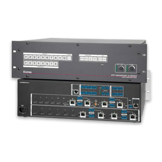
- Page 1 User Guide Matrix Switchers DTP CrossPoint 4K Series Scaling Presentation Matrix Switchers 68-2368-01 Rev. B 09 16...
-
Page 2: Safety Instructions
Safety Instructions Safety Instructions • English Istruzioni di sicurezza • Italiano WARNING: This symbol, , when used on the product, is intended to AVVERTENZA: Il simbolo, , se usato sul prodotto, serve ad alert the user of the presence of uninsulated dangerous voltage within avvertire l’utente della presenza di tensione non isolata pericolosa the product’s enclosure that may present a risk of electric shock. - Page 3 より 『Extron Safety www.extron.com and Regulatory Compliance Guide』 (P/N 68-290-01) をご覧ください。 Copyright © 2016 Extron Electronics. All rights reserved. Trademarks All trademarks mentioned in this guide are the properties of their respective owners. The following registered trademarks , registered service marks( ), and trademarks( ) are the property of RGB Systems, Inc.
- Page 4 FCC Class A Notice This equipment has been tested and found to comply with the limits for a Class A digital device, pursuant to part 15 of the FCC rules. The Class A limits provide reasonable protection against harmful interference when the equipment is operated in a commercial environment.
- Page 5 Conventions Used in this Guide Notifications The following notifications are used: WARNING: Potential risk of severe injury or death. AVERTISSEMENT : Risque potentiel de blessure grave ou de mort. ATTENTION: • Risk of property damage. • Risque de dommages matériels. NOTE: A note draws attention to important information.
-
Page 7: Table Of Contents
Recalling Presets .......... 41 and Communications Protocol Commands ..83 Assigning and Unassigning Logos ....43 IPCP Pro 350 Information ......83 Configuring the Input Audio ......45 Special Characters ........... 84 DTP CrossPoint 4K Series Matrix Switchers • Contents... - Page 8 Finalizing the Output Gain Structure .... 149 Setting the Mic Input and Mic Mix-point Levels ............150 Adjusting the Post-matrix Trim ....150 Setting the Volume Control for an External Amplifier ........150 Calibrating Loudness ........151 DTP CrossPoint 4K Series Matrix Switchers • Contents viii...
-
Page 9: Introduction
It can route multiple input and output configurations simultaneously. The Extron DTP CrossPoint 4K Series provide HDMI and DTP twisted pair inputs and outputs, 4K scaling, and audio DSP with AEC. Most model include an integrated audio power amplifier and a built-in IPCP Pro 350 control processor. - Page 10 Adjustable mic input audio gain and attenuation compensates for level differences among audio inputs. The DTP CrossPoint 4K Series also include a built-in digital signal processor (DSP) that provides a wide variety of microphone pre-amplifier controls, mixers, filters, dynamics processors, and feedback suppressors.
-
Page 11: Dtp Input And Output Signals
DTP CrossPoint switcher. Depending on the transmitting or receiving device, the DTP inputs and outputs can travel up to 330 feet (100 meters) or 230 feet (70 meters) without a loss of signal integrity. DTP CrossPoint 4K Series Matrix Switchers • Introduction... -
Page 12: Definitions
• When a preset consisting of one or more partial configurations is recalled, it overwrites only a portion of the current configuration, leaving other ties and settings unchanged. DTP CrossPoint 4K Series Matrix Switchers • Introduction... -
Page 13: Features
Features All-in-one matrix switcher, scaler, and audio DSP — The DTP CrossPoint 4K Series • delivers all of the core functionality of a conventional AV system in a single enclosure, making it ideal for presentation environments that require multiple displays. - Page 14 Remote powering of DTP transmitters and receivers — The • DTP CrossPoint 4K Series can provide power to four DTP transmitters and four DTP receivers over the twisted pair connections, eliminating the need for separate power supplies at the remote units.
- Page 15 DSP Configurator Software — A powerful yet user-friendly PC-based software tool for managing all audio operations of the DTP CrossPoint 4K Series. It enables complete setup and configuration of digital audio processing tools on the DSP platform, as well as routing and mixing.
- Page 16 DTP CrossPoint 4K Series Matrix Switchers • Introduction...
- Page 17 Easy setup and commissioning with the Extron Product Configuration Software (PCS) — Conveniently configure multiple products using a single software application. • Rack-mountable 3U or 2U, full rack width metal enclosure • Includes LockIt HDMI cable lacing brackets DTP CrossPoint 4K Series Matrix Switchers • Introduction...
-
Page 18: Installation
Front Panel Configuration Port Setup and Installation Checklist Preparation Familiarize yourself with the DTP CrossPoint 4K Series matrix switcher. Obtain IP setting information for the matrix switcher from the local network administrator (see the IPCP Pro Series User Guide at www.extron.com). -
Page 19: Rear Panel Cabling And Features
Audio Input and Output Connections (see page 15) Serial and IR Insertion Connections (see page 16) • • Control Connections (see page 17) • Switcher Reset (see page 18) Power (see page 18) • DTP CrossPoint 4K Series Matrix Switchers • Installation... -
Page 20: Video And Twisted Pair Input And Output Connections And Switches
Position this switch BEFORE connecting the appropriate device to the TP connector. Failure to comply can damage the endpoint. • Positionnez le sélecteur AVANT de connecter l’appareil approprié au connecteur TP. Ne pas respecter cette procédure pourrait endommager le point de connexion. DTP CrossPoint 4K Series Matrix Switchers • Installation... - Page 21 Position this switch BEFORE connecting the appropriate device to the TP connector. Failure to comply can damage the endpoint. • Positionnez le sélecteur AVANT de connecter l’appareil approprié au connecteur TP. Ne pas respecter cette procédure pourrait endommager le point de connexion. DTP CrossPoint 4K Series Matrix Switchers • Installation...
- Page 22 Ne connectez pas ces port à des données informatiques ou à un réseau de télécommunications. The video and embedded audio signal output on the TP output nB output is NOTE: duplicated on nA HDMI (for example, output 5A duplicates output 5B). DTP CrossPoint 4K Series Matrix Switchers • Installation...
-
Page 23: Audio Input And Output Connections
Ensure the rated input voltage of the speakers matches the rated output voltage of the switcher. • Assurez-vous que la tension nominale d’entrée des enceintes soit compatible avec la tension nominale de sortie du sélecteur. DTP CrossPoint 4K Series Matrix Switchers • Installation... -
Page 24: Serial And Ir Insertion Connections
The following table identifies the Over TP outputs by matrix size. Matrix Outputs Matrix Outputs 10x8 5B, 6B, 7, 8 3B, 4B, 5, 6 3B, 4B 1B, 2B DTP CrossPoint 4K Series Matrix Switchers • Installation... -
Page 25: Control Connections
Remote port — Plug a serial RS-232 device into the matrix REMOTE switcher via this 3.5 mm, 3-pole captive screw connector for remote control of the switcher (see Serial and IR port connectors page 23 to wire the connector). Tx Rx G DTP CrossPoint 4K Series Matrix Switchers • Installation... -
Page 26: Switcher Reset
Power Connector, 8x4 Matrix Power connector — Plug a standard IEC power cord into this connector to connect the switcher to a 100 VAC to 240 VAC, 50-60 Hz power source. 50-60 Hz DTP CrossPoint 4K Series Matrix Switchers • Installation... -
Page 27: Detailed Pin Assignments, Wiring, And Sample Applications
Connector and T568B at the other (Tx and Rx pairs called a "straight-through" cable, because reversed) is a "crossover" cable. no pin/pair assignments are swapped. Figure 17. RJ-45 Connector and Pinout Tables DTP CrossPoint 4K Series Matrix Switchers • Installation... - Page 28 Les ports paires torsadées peuvent fournir une alimentation à distance aux appareils connectés. L’alimentation à distance est exclusivement réservée à un usage en intérieur. Un réseau utilisant une alimentation à distance ne peut pas être routé en extérieur. DTP CrossPoint 4K Series Matrix Switchers • Installation...
- Page 29 3.5 mm Stereo Plug Connector tip, and sleeve wires are also shown on the captive screw audio connector diagrams, figure 18, figure 19 on the next page, and figure 20 on the next page. DTP CrossPoint 4K Series Matrix Switchers • Installation...
- Page 30 Output signal processor chain, Volume controls on page 116). From DSP You can make audio breakaway ties with an SIS command (see page 71) or the Product Matrix Software Configuration Software (see on page 85). DTP CrossPoint 4K Series Matrix Switchers • Installation...
- Page 31 Figure 22 shows the cable wiring for the S/PDIF jack. This is a 75-ohm cable with a standard RCA connector. Tip (+) Sleeve ( ) RCA Connector Figure 22. Wiring an RCA Connector for the S/PDIF Jack DTP CrossPoint 4K Series Matrix Switchers • Installation...
-
Page 32: Front Panel Configuration Port
NOTE: A front panel Configuration port connection and a rear panel Remote port connection can both be active at the same time. If commands are sent simultaneously to both, the command that reaches the processor first is handled first. DTP CrossPoint 4K Series Matrix Switchers • Installation... -
Page 33: Operation
Operation This section describes the front panel operation of the DTP CrossPoint 4K Series, including: Front Panel Controls and Indicators • • Front Panel Operations • Rear Panel Operations Ethernet to RS-232 Insertion • • Troubleshooting Configuration Worksheets • Front Panel Controls and Indicators... - Page 34 OUTPUTS Extron DTP CROSSPOINT 4K SERIES DIGITAL PRESENTATION SWITCHER D E F G H I Figure 25. Front Panel, DTP CrossPoint 4K Series (IPCP Model) Input buttons (see page 27) Esc button (see page 31) Output buttons (see page 29)
-
Page 35: Input And Output Buttons
(Selected inputs, based on matrix size) Select and display the control insert • configuration for input. (Input 1 and Input 2 only) Toggle background illumination of the buttons on and • off. DTP CrossPoint 4K Series Matrix Switchers • Operation... - Page 36 NOTE: See Front Panel Operations, beginning on page 34, for detailed descriptions of the following operations. Input and Output button secondary functions (continued) 10x8 matrix 8x6 matrix 8x4 matrix 8x2 matrix Control Action 1 Input 4 insert blink: Output 4 configuration Select config.
-
Page 37: Logo Button
5 through 8 (scaled outputs). NOTES: • The switcher has memory space for 16 bitmapped logos. • Logos are created and saved using the Product Configuration Software (see the PCS Help file). DTP CrossPoint 4K Series Matrix Switchers • Operation... -
Page 38: Control Buttons
Selects 19200 baud for the rear panel Remote port in Serial Port Configuration • mode and indicates the selection. With the View and Esc buttons, selects front panel security Lock mode 2 or • toggles between mode 0 (unlocked) and mode 2. DTP CrossPoint 4K Series Matrix Switchers • Operation... - Page 39 With the Preset button and View button, selects between front panel locks • (Lock mode 2 and Lock mode 0). With the View button, selects between front panel locks (Lock mode 2 and • Lock mode 1). DTP CrossPoint 4K Series Matrix Switchers • Operation...
-
Page 40: I/O Buttons
The sensitivity of the encoder (the amount [dB] of volume adjustment per step of rotation) varies depending on the current volume setting (see the last column in the table). DTP CrossPoint 4K Series Matrix Switchers • Operation... -
Page 41: Control Processor Indications
171, for details on using the labeling software, blank labels you can fill in yourself, and a procedure for removing and replacing the translucent covers. INPUTS 9 10 Computer 6 7 8 Document Camera OUTPUTS Figure 26. Sample Button Icons DTP CrossPoint 4K Series Matrix Switchers • Operation... -
Page 42: Front Panel Operations
NOTE: The switcher is shipped from the factory in Lock mode 2. See Setting the Front Panel Locks (Executive Modes) on page 48 for a detailed list of basic and advanced functions and the procedure to set the various front panel locks. DTP CrossPoint 4K Series Matrix Switchers • Operation... -
Page 43: Making Ties
Outputs that are already tied can be left on, along with new blinking selections, or toggled off by pressing the associated output button. DTP CrossPoint 4K Series Matrix Switchers • Operation... - Page 44 The current configuration (see figure 27) is now input 5 video and audio tied to output 1, output 3, and output 4. Input Video Output Audio Figure 27. Final Configuration, Example 1 DTP CrossPoint 4K Series Matrix Switchers • Operation...
- Page 45 Video — Input 5 video is tied to output 1, output 2, output 3, and output 4. Audio — Input 5 audio is tied to output 1, output 3, and output 4. • Input Video Output Audio Figure 28. Final Configuration, Example 2 DTP CrossPoint 4K Series Matrix Switchers • Operation...
- Page 46 Video — Input 5 video is tied to output 1, output 2, output 3, and output 4. • • Audio — Input 5 audio is tied to output 1 and output 3. Input Video Output Audio Figure 29. Final Configuration, Example 3 DTP CrossPoint 4K Series Matrix Switchers • Operation...
-
Page 47: Viewing The Configuration
Amber if no inputs are tied (not shown in this example) Green if no video inputs are tied (only audio is tied) Red if no audio inputs are tied (only video is tied). OUTPUTS DTP CrossPoint 4K Series Matrix Switchers • Operation... - Page 48 The output buttons for outputs that are tied to Input 5 light green to indicate video ties (audio breakaway). OUTPUTS The output buttons for outputs that are not tied to Input 5 are either unlit or background illuminated. DTP CrossPoint 4K Series Matrix Switchers • Operation...
-
Page 49: Recalling Presets
Preset Preset Preset Preset Preset Preset Preset Preset Preset Preset INPUTS Input 8x4 and buttons 8x2 Matrix Sizes Output buttons OUTPUTS Preset Preset Preset Preset Figure 30. DTP CrossPoint 4K Preset Locations DTP CrossPoint 4K Series Matrix Switchers • Operation... - Page 50 C O N T R O L VIEW ENTER PRESET The Enter and Preset buttons return to unlit or background illumination. OUTPUTS All input and output buttons return to unlit or background illumination. DTP CrossPoint 4K Series Matrix Switchers • Operation...
-
Page 51: Assigning And Unassigning Logos
Enter Press the Enter button to confirm the change. All input buttons and output buttons ENTER return to unlit or background illumination. The Enter button returns to unlit or background illumination. DTP CrossPoint 4K Series Matrix Switchers • Operation... - Page 52 Enter Press the Enter button to confirm the change. All input buttons and output buttons ENTER return to unlit or background illumination. The Enter button returns to unlit or background illumination. DTP CrossPoint 4K Series Matrix Switchers • Operation...
-
Page 53: Configuring The Input Audio
All input buttons and output buttons ENTER return to unlit or background illumination. The Enter button returns to unlit or background illumination. Repeat steps 2 through 5 as necessary for other inputs. DTP CrossPoint 4K Series Matrix Switchers • Operation... -
Page 54: Configuring The Tp Insertion Ports
The selected input or output button indicates the control insertion configuration as follows: Press Unlit — RS-232 pass-through Amber — Ethernet CONTROL ENTER PRESET VIEW Press The Enter button blinks to indicate the need to save the change. DTP CrossPoint 4K Series Matrix Switchers • Operation... -
Page 55: Selecting The Remote Port Baud Rate
All Control and I/O buttons return Press and release to unlit or background illumination. an output button. C O N T R O L I / O VIEW ENTER PRESET VIDEO AUDIO DTP CrossPoint 4K Series Matrix Switchers • Operation... -
Page 56: Background Illumination
• Recalling presets • Changing Lock modes • Advanced functions consist of: Configuring the TP insertion ports • Configuring the input audio • Setting the rear panel remote port baud rate • DTP CrossPoint 4K Series Matrix Switchers • Operation... -
Page 57: Selecting Lock Mode 2 Or Toggling Between Mode 2 And Mode 0
AUDIO ENTER PRESET VIDEO AUDIO VIEW VIDEO AUDIO Press and hold for Press and hold for 2 seconds. 2 seconds. Figure 33. Toggle Front Panel Lock Between Mode 2 and Mode 1 DTP CrossPoint 4K Series Matrix Switchers • Operation... -
Page 58: Performing A System Reset From The Front Panel
NOTE: If background illumination was turned on before the reset, the I/O and control buttons are unlit after the reset. When you cycle power, background illumination returns to the condition that you previously selected. DTP CrossPoint 4K Series Matrix Switchers • Operation... -
Page 59: Rear Panel Operations
HDMI mutes, second momentary press does not occur enables all RS-232 pass-throughs, within 1 second. clears all audio settings. • Resets all IP options. The Reset LED blinks four times in quick succession. DTP CrossPoint 4K Series Matrix Switchers • Operation... -
Page 60: Performing A Mode 1 Reset
Continue to hold the Reset button until all input and output buttons return to either unlit or to background illumination and the Video and Audio buttons turn on. Release the Reset button. RESET Figure 35. Hard Reset DTP CrossPoint 4K Series Matrix Switchers • Operation... -
Page 61: Performing Mode 4 And Mode 5 Resets
You must physically connect a cable connected to the captive screw connector where a control signal is to be inserted. The insert inputs and outputs, whether inserted via Ethernet or captive screw connectors, can support up to a 115k baud rate. DTP CrossPoint 4K Series Matrix Switchers • Operation... -
Page 62: Enabling Ethernet And Captive Screw Insertion
POWER AUDIO RS-232 0.7A MAX Tx Rx Tx Rx Tx Rx DTP OUT DTP HDMI 4K 230 Tx RS-232 HD Camera Figure 37. Typical Ethernet to RS-232 Insertion to an Input Endpoint DTP CrossPoint 4K Series Matrix Switchers • Operation... - Page 63 Parameters, steps 1, 4, and 5, on page 91). Alternatively, you can change the port RS-232 settings via SIS commands (see the Ethernet insertion serial port insert parameters SIS command on page 81). DTP CrossPoint 4K Series Matrix Switchers • Operation...
-
Page 64: Captive Screw Signal Insertion
Ensure that the proper signal format is supplied. Check the cabling and make corrections as necessary. Call the Extron S3 Sales and Technical Support Hotline if necessary. See www.extron.com for the phone number in your region of the world. DTP CrossPoint 4K Series Matrix Switchers • Operation... -
Page 65: Configuration Worksheets
An audio test tape or CD can be used in a similar manner to check out the audio components. DTP CrossPoint 4K Series Matrix Switchers • Operation... -
Page 66: Worksheet Example 2: Daily Configuration
Fill in the preset number and use colors, dashes, etc., to make connecting lines. Indicate if the configuration is for video, audio, or both. indicates paired outputs Figure 41. Worksheet Example 3: Test Configuration DTP CrossPoint 4K Series Matrix Switchers • Operation... -
Page 67: Worksheets
Preset # Title: Video: Audio: Fill in the preset number and use colors, or dashes, etc. to make connecting lines. Indicate if the configuration is for video, audio, or both. indicates paired outputs DTP CrossPoint 4K Series Matrix Switchers • Operation... - Page 68 Preset # Title: Video: Audio: Fill in the preset number and use colors, or dashes, etc. to make connecting lines. Indicate if the configuration is for video, audio, or both. indicates paired outputs DTP CrossPoint 4K Series Matrix Switchers • Operation...
- Page 69 Preset # Title: Video: Audio: Fill in the preset number and use colors, or dashes, etc. to make connecting lines. Indicate if the configuration is for video, audio, or both. indicates paired outputs DTP CrossPoint 4K Series Matrix Switchers • Operation...
- Page 70 Preset # Title: Video: Audio: Fill in the preset number and use colors, or dashes, etc. to make connecting lines. Indicate if the configuration is for video, audio, or both. indicates paired outputs DTP CrossPoint 4K Series Matrix Switchers • Operation...
-
Page 71: Programming Guide
1 stop bit Selecting the Remote Port Baud Rate on page 47 to configure the rear panel Remote port from the front panel. Extron recommends leaving the Remote port at 9600 baud. DTP CrossPoint 4K Series Matrix Switchers • Programming Guide... -
Page 72: Usb Port
The LAN ports give access to either the DTP CrossPoint or the built-in IPCP control processor. • The unused ports function as a simple, multiport, unmanaged network switch so that you can connect additional devices to the same network. DTP CrossPoint 4K Series Matrix Switchers • Programming Guide... -
Page 73: Establishing A Connection
For a Telnet session to receive change notices from the switcher, the Telnet session must be in verbose mode 1 or 3 (see the Verbose Mode SIS command on page 83). DTP CrossPoint 4K Series Matrix Switchers • Programming Guide... -
Page 74: Host-To-Switcher Instructions
“ ” is the executive mode: , or . See Setting the Front Panel Locks (Executive Modes) on page 48 for more information on the Lock modes. DTP CrossPoint 4K Series Matrix Switchers • Programming Guide... -
Page 75: Switcher Error Responses
The SIS commands are not case sensitive. The ASCII to HEX conversion table below is for use with the command and response table. ASCII to Hex Conversion Table Space • DTP CrossPoint 4K Series Matrix Switchers • Programming Guide... -
Page 76: General Matrix Switcher Commands
= Monitor connected but does not support HDCP = Monitor connected, supports HDCP, but the video signal is not encrypted = Monitor connected, supports HDCP, and the video signal is encrypted DTP CrossPoint 4K Series Matrix Switchers • Programming Guide... - Page 77 8x6 matrix and 8x4 matrix = Input 7 = Output 3 = Input 8 = Output 4 8x2 matrix = Input 7 = Output 1 = Input 8 = Output 2 DTP CrossPoint 4K Series Matrix Switchers • Programming Guide...
- Page 78 = input 7 and input 8 2003 2004 = output 3 and output 4 8x2 matrix: = input 7 and 8 2001 2002 = output 1 and output 2 2003 2004 DTP CrossPoint 4K Series Matrix Switchers • Programming Guide...
-
Page 79: Command And Response Table For Matrix Switcher Commands
= 0.2 seconds) = Input number – the highest numbered input for your model ( = untied input) = Output number – the highest numbered output for your model ( = untied output) DTP CrossPoint 4K Series Matrix Switchers • Programming Guide... - Page 80 = Auto (see the Example 2, above) (default) = HDMI (digital audio) = Analog 2-channel audio = Output audio source = Original HDMI audio = Embed audio (from DSP) = None DTP CrossPoint 4K Series Matrix Switchers • Programming Guide...
- Page 81 EDID Values Table Source or value Source or value Source or value Source or value by matrix size by matrix size by matrix size by matrix size Assigned output values Output 1 Output 3 Output 5A Output 1A Output 3A Output 5B Output 1B Output 3B...
- Page 82 = HDMI YUV Full (RGB 422, 000 - 255 audio, InfoFrames) = HDMI YUV Limited (RGB 422, 016 - 255 audio, InfoFrames) = Output video bit depth = Auto (default) = 8-bit DTP CrossPoint 4K Series Matrix Switchers • Programming Guide...
- Page 83 = HDBT (output only) = XTP X2$ = Name Up to 12 upper- and lower-case alphanumeric characters, _, /, and spaces X2% = Scaler preset – X2^ = Logo number – DTP CrossPoint 4K Series Matrix Switchers • Programming Guide...
- Page 84 = Preset number – = Lock mode = Mode 0 = Mode 1 = Mode 2 (default) = Firmware version number to second decimal place (x.xx) = Verbose firmware version-description-upload date and time. DTP CrossPoint 4K Series Matrix Switchers • Programming Guide...
- Page 85 – the highest numbered input for your model = Input number = Voltage Positive or negative voltage and magnitude = Internal temperature Degrees Celsius = Picture adjustments 000 through 127 (064 = default) DTP CrossPoint 4K Series Matrix Switchers • Programming Guide...
- Page 86 (Horizontal is specified from left, vertical from top 10240 = Active pixels and active lines Dependent on the input signal and selected scaling. = Aspect ratio fill or follow = fill (default) = follow DTP CrossPoint 4K Series Matrix Switchers • Programming Guide...
-
Page 87: Test Pattern
= Active input detected, timer is not running = No active input, timer is running, output sync is still active = No active input, timer is expired, output sync is disabled. DTP CrossPoint 4K Series Matrix Switchers • Programming Guide... - Page 88 = Input number – the highest numbered input for your model = Film mode auto detect = Enable = Disable (default) = Scaler output resolution and rate See the table above. DTP CrossPoint 4K Series Matrix Switchers • Programming Guide...
- Page 89 70) The starting point ( ) is the rear panel Remote RS-232 port. The next positions ( through ) are DTP inputs. The next positions ( through ) are DTP outputs. DTP CrossPoint 4K Series Matrix Switchers • Programming Guide...
-
Page 90: Port Specific And Communications Protocol Sis Commands
(for example, the read matrix name command , returns • X7& = Port timeout interval (in 10-second increments) (= 10 seconds) - 65000 (default is = 300 seconds = 5 minutes) DTP CrossPoint 4K Series Matrix Switchers • Programming Guide... -
Page 91: Command And Response Table For Remote And Communications Protocol Commands
Disable Telnet port Pmt00000 View Telnet port map <port #> Set Web port map <port #>MH Pmh<port #> Reset Web port 80MH Pmt00080 Disable Web port Pmh00000 View Web port map <port #> DTP CrossPoint 4K Series Matrix Switchers • Programming Guide... -
Page 92: Ipcp Pro 350 Information
The switcher rejects the following characters: {space (spaces are valid for use in names)} + ~ , @ = ‘ [ ] { } < > ’ “ semicolon (;) colon (:) | \ and ?. DTP CrossPoint 4K Series Matrix Switchers • Programming Guide... -
Page 93: Matrix Software
PCS. This protects the DSP settings against inadvertent changes made by the more basic PCS audio adjustment capabilities. This software lock can be overridden, but Extron STRONGLY advises against doing so. DTP CrossPoint 4K Series Matrix Switchers • Matrix Software... -
Page 94: Software Operational Considerations And Installation
2 2 2 2 — OR — 3 3 3 3 3 3 3 3 2 2 2 2 2 2 2 2 Figure 42. Downloading a Software or Firmware Package (PCS Shown) DTP CrossPoint 4K Series Matrix Switchers • Matrix Software... - Page 95 For a firmware download, exit this procedure and return to Updating the Firmware Update the Firmware in this Matrix Software section on page 93 or in the HTML Pages section on page 156. DTP CrossPoint 4K Series Matrix Switchers • Matrix Software...
-
Page 96: Product Configuration Software
All Programs Extron Electronics Extron Product > Configuration Software Extron Product Configuration Software The Product Configuration Software opens to the screen (see figure 45). Device Discovery Figure 45. Device Discovery Screen DTP CrossPoint 4K Series Matrix Switchers • Matrix Software... -
Page 97: Device Menu
Open and Apply — Opens a saved configuration file and applies its settings to the • connected device shown on the currently selected device tab. • Disconnect — Disconnects the PCS from the unit while leaving the program active. DTP CrossPoint 4K Series Matrix Switchers • Matrix Software... -
Page 98: Assigning And Unassigning Logos
2 2 2 2 2 2 2 2 4 4 4 4 4 4 4 4 3 3 3 3 3 3 3 3 Figure 47. Scaler Settings Panel, DTP CrossPoint 108 4K Shown DTP CrossPoint 4K Series Matrix Switchers • Matrix Software... -
Page 99: Configuring Rs-232 Insertion Parameters
General Settings Panel, DTP CrossPoint 108 4K Shown Double-click the port to be configured ( ) or click the Gear icon ( ). The Configure Port dialog box opens (see figure 49 on the next page). DTP CrossPoint 4K Series Matrix Switchers • Matrix Software... - Page 100 If you want to change the change the port number starting point, click in the Starting Point box and type in a new value (see Port number on page 55 to understand how this affects insertion port numbering). DTP CrossPoint 4K Series Matrix Switchers • Matrix Software...
-
Page 101: Updating The Firmware
[IPCP models] both on page 17) or front panel Configuration port (see item on page 24). Starting the Start the Product Configuration Software and connect to the unit (see Program on page 88). DTP CrossPoint 4K Series Matrix Switchers • Matrix Software... - Page 102 On the DTP CrossPoint tab, click > > Update firmware Update Firmware this . The software asks you to confirm that you want to continue the update (see Device figure 51 on the next page). DTP CrossPoint 4K Series Matrix Switchers • Matrix Software...
- Page 103 . The Product Configuration Software window returns to the front. Close Click the in the connection tab to completely disconnect the program from the unit and then reconnect the program as described in Starting the Program on page 88. DTP CrossPoint 4K Series Matrix Switchers • Matrix Software...
-
Page 104: Dsp Configurator Program
Configurator program. Start the DSP Configurator Program by clicking the desktop icon or as follows: Click Start > All Programs > Extron Electronics > DSP Configurator > DSP . The DSP Configurator startup screen displays (see figure 52). Configurator 1 1 1 1... - Page 105 * This output 1 amplifier block (in ) is not present on non-IPCP models. Figure 53. DSP Configurator (SA) Program Window, DTP CrossPoint 108 Shown DTP CrossPoint 4K Series Matrix Switchers • Matrix Software...
-
Page 106: Using The Program
Mic-to-virtual-send-bus mixer block page 117) Virtual returns-to-virtual-send-bus mixer block (see Virtual returns-to-virtual-send- bus mixer block on page 117) Expansion inputs-to-virtual-send-bus mixer block (see Expansion inputs-to-virtual- send-bus mixer block on page 117) DTP CrossPoint 4K Series Matrix Switchers • Matrix Software... - Page 107 Click to select process, double-click the block again, opening a processes available the desired process. separate window. in this block. Figure 55. Selecting and Inserting a Typical Processor Block Dialog Box DTP CrossPoint 4K Series Matrix Switchers • Matrix Software...
- Page 108 When a processor is bypassed, a red indicator in the block turns on. The block can be removed from the audio stream by selecting it and depressing the keyboard < > key or by right-clicking and selecting Delete Delete DTP CrossPoint 4K Series Matrix Switchers • Matrix Software...
- Page 109 Output Signal Source of that output is set to (see item Output signal processor Original chain Volume controls on page 116). Analog input audio is not passed to any output. • DTP CrossPoint 4K Series Matrix Switchers • Matrix Software...
- Page 110 When one or both channels are muted, one or two red indicators in the block turn on. The mute controls are common to both digital and analog signals. NOTE: When the left and right channels are ganged, either button mutes and Mute unmutes both channels. DTP CrossPoint 4K Series Matrix Switchers • Matrix Software...
- Page 111 Notch filter — These filters attenuate a narrow band of frequencies to minimize feedback. Loudness filter — Not currently functional. DTP CrossPoint 4K Series Matrix Switchers • Matrix Software...
- Page 112 When you select either Feet Meters you can also specify a temperature, in either degrees Fahrenheit or degrees Celsius The processor calculates the change in speed of sound for the specified temperature. DTP CrossPoint 4K Series Matrix Switchers • Matrix Software...
- Page 113 Line audio Filter block on page 103 (except that up to five filters total can be selected for this block). NOTE: Selecting inserts two separate filters. Bass & Treble Filter DTP CrossPoint 4K Series Matrix Switchers • Matrix Software...
- Page 114 Dynamics blocks (2) — The two dynamics processor blocks, when inserted, each provide one of four dynamic processors. The available processors are as described for the Line audio Dynamics block on page 104. DTP CrossPoint 4K Series Matrix Switchers • Matrix Software...
- Page 115 The current source is not available as a target (a source cannot duck itself). If the current source has been designated as a target of another input channel, that input channel is not available (a target cannot be the source). DTP CrossPoint 4K Series Matrix Switchers • Matrix Software...
- Page 116 None ¢ Show AM Group Details — Opens a dialog box that details current groups and the parameter member assignments to each (see Automix Group Details on page 144 for particulars). DTP CrossPoint 4K Series Matrix Switchers • Matrix Software...
- Page 117 119 to create group masters). • Multiple masters can be created for a fader, in which case the indicator is • By default, the front panel Mic Volume knob controls this fader. DTP CrossPoint 4K Series Matrix Switchers • Matrix Software...
- Page 118 12 dB to -100 dB, adjustable in 0.1 dB increments. The Gain block is identical to as described for the Mic/line inputs signals Gain block on page 101. DTP CrossPoint 4K Series Matrix Switchers • Matrix Software...
- Page 119 119 to create group masters). • Multiple masters can be created for a fader, in which case the indicator is • By default, the front panel Volume knob controls this fader. DTP CrossPoint 4K Series Matrix Switchers • Matrix Software...
- Page 120 If an audio signal is output on the virtual bus and looped around back to the virtual input, mute the audio output by the AV block in these mix-points to prevent the unprocessed signal from being output along with the processed audio. DTP CrossPoint 4K Series Matrix Switchers • Matrix Software...
- Page 121 In the first block (column) of mix-points, audio is redirected up. In the second column, audio is redirected down. The virtual send bus does not exit the DSP, but is looped around for potential additional • processing. DTP CrossPoint 4K Series Matrix Switchers • Matrix Software...
- Page 122 3 3 3 3 4 4 4 4 4 4 4 4 2 2 2 2 2 2 2 2 Figure 59. Output Mixer Blocks and Mix-points, DTP CrossPoint 108 4K Shown DTP CrossPoint 4K Series Matrix Switchers • Matrix Software...
- Page 123 The delay processor block is identical to as described for the Line audio Delay block on page 104. DTP CrossPoint 4K Series Matrix Switchers • Matrix Software...
- Page 124 6 6 6 6 6 6 6 6 Mono Audio Ampifier Control Analog Volume and SA Models HDMI and DTP Volume Control MA Models Only Amplifier Control Figure 60. Analog and Digital Volume Controls DTP CrossPoint 4K Series Matrix Switchers • Matrix Software...
- Page 125 The functions and indications of the mix-points and the dialog boxes are as described for Mic-to-output mixer block on pages 114 and 115 DTP CrossPoint 4K Series Matrix Switchers • Matrix Software...
- Page 126 4 4 4 4 1 1 1 1 1 1 1 1 2 2 2 2 2 2 2 2 Figure 61. Virtual Send Bus and Expansion Bus Mixer Blocks and Mix-points DTP CrossPoint 4K Series Matrix Switchers • Matrix Software...
-
Page 127: Group Masters
The output 1 through output 3 analog volume controls can be grouped into a master that controls the volume throughout the room (see figure 63). DTP CrossPoint 4K Series Matrix Switchers • Matrix Software... -
Page 128: Configuring A Group Master
Numbered groups <empty> (such as ) or otherwise named groups have controls assigned that may be Group # overwritten if you select them and continue. DTP CrossPoint 4K Series Matrix Switchers • Matrix Software... - Page 129 Soft limits can be defined using the mouse by clicking and dragging the Soft Limit icon. The resolution is 0.1 dB. For more precise setting, using the keyboard (see Setting group master soft limits on page 135). DTP CrossPoint 4K Series Matrix Switchers • Matrix Software...
- Page 130 The size of the increment can be changed from its default value of by typing 1 dB a value in the field, to as fine as Increment Value Decrement Value 1 dB DTP CrossPoint 4K Series Matrix Switchers • Matrix Software...
- Page 131 > key. Switching operations using View > Video I/O the AV matrix block (see AV matrix block ( on page 110) tie only video (video breakaway). Figure 68. DSP Configurator Program Window, Video-only I/O Page DTP CrossPoint 4K Series Matrix Switchers • Matrix Software...
-
Page 132: Presets
110) tie only audio. Presets The DTP CrossPoint 4K Series can store up to 32 presets and can include both selected ties and selected audio signal processing settings made in the program. Presets that do not include a full configuration of ties and settings, when recalled, overwrite only a portion of the current configuration, leaving other ties and settings unchanged, and are useful when only selected ties, settings, or both;... -
Page 133: Recall A Preset
( Recall TIPS: • Click to discard the preset recall (but not deleting the preset) and return Cancel to the current configuration. • Click to permanently erase the preset. Delete DTP CrossPoint 4K Series Matrix Switchers • Matrix Software... -
Page 134: Emulate Mode Vs. Live Mode
TCP/IP next page). • tab ( ) (for front panel Configuration port connection — Proceed to step NOTE: Do not select the RS-232 tab. Configuration is too complex for this port. DTP CrossPoint 4K Series Matrix Switchers • Matrix Software... - Page 135 Clicked in step 6c — Click Selected Select the desired presets to push by clicking the appropriate check boxes ( Click ). Proceed to step 8 on page 129). ¢ DTP CrossPoint 4K Series Matrix Switchers • Matrix Software...
- Page 136 9 9 9 9 9 9 9 9 ¢ ¢ ¢ ¢ ¢ ¢ ¢ ¢ ¢ ¢ £ £ £ £ £ £ £ £ £ £ Figure 71. Selecting Live Mode, Continued DTP CrossPoint 4K Series Matrix Switchers • Matrix Software...
-
Page 137: Dsp Configurator Windows Menus
Copy — Copies all of the parameters of a selected processor block, gain block, or set of selected blocks to the clipboard. Paste — Inserts processor blocks and their parameters from the clipboard into the DSP Configurator program at the location selected. DTP CrossPoint 4K Series Matrix Switchers • Matrix Software... - Page 138 Issue RESET Command — Initializes and clears any or all of the following: ties, mic mixes, presets, audio configuration, processor blocks, and gain blocks. This reset is identical to the SIS command (see the System Reset SIS command page 76). ZXXX DTP CrossPoint 4K Series Matrix Switchers • Matrix Software...
-
Page 139: Dsp Configurator Help Selection
DSP Configurator. The ties and settings of the preset are not in sync between the DSP Configurator program and the switcher. DTP CrossPoint 4K Series Matrix Switchers • Matrix Software... -
Page 140: Keyboard Navigation
(line signal processor chain [see figure 73, ]). The Input 1 Gain block is highlighted green ( ). * This output 1 amplifier block is not present on non-IPCP models. Figure 73. DSP Configurator Program Window DTP CrossPoint 4K Series Matrix Switchers • Matrix Software... -
Page 141: Standard Windows Navigation
Press <Enter> to execute the tie. If desired to make additional ties from the same input, press up arrow or down arrow (<Shift> is not required) to select another output to tie to the same input. DTP CrossPoint 4K Series Matrix Switchers • Matrix Software... - Page 142 NOTE: Unless you enter a specific number, name, or both, DSP Configurator enters the next sequential unused preset number and the name Preset number Press <Tab> to highlight the button ( ) and press <Enter> ( DTP CrossPoint 4K Series Matrix Switchers • Matrix Software...
- Page 143 <Ctrl>-<Page Up> or <Ctrl>-<Page Down> — Moves the soft lower limit in • 10 dB increments. <Ctrl>-<Home> — Moves the soft lower limit to the fader position. • <Ctrl>-<End> — Moves the soft lower limit to the lower default. • DTP CrossPoint 4K Series Matrix Switchers • Matrix Software...
-
Page 144: Signal Path Building Blocks
The building blocks can be renamed and processor blocks further customized according to the requirements of the system. * This output 1 amplifier block is not present on non-IPCP models. Figure 75. Building Blocks Availability DTP CrossPoint 4K Series Matrix Switchers • Matrix Software... - Page 145 Handheld mic available for selection. Click the desired input device. The input device name and the processor chain change to shows the adjustments. 2 2 2 2 2 2 2 2 DTP CrossPoint 4K Series Matrix Switchers • Matrix Software...
- Page 146 : drop-down menu ( Create In 1 1 1 1 1 1 1 1 2 2 2 2 2 2 2 2 DTP CrossPoint 4K Series Matrix Switchers • Matrix Software...
- Page 147 This utility lets you organize listed building blocks. You can also import and export the building blocks file so that you can use your set of building blocks on other computers. DTP CrossPoint 4K Series Matrix Switchers • Matrix Software...
- Page 148 Import Building Blocks File Import from opens. Browse to and select the desired building blocks file. Click . The selected building blocks file is imported into the Open Organize Building dialog box. Blocks DTP CrossPoint 4K Series Matrix Switchers • Matrix Software...
-
Page 149: Aec Tutorial
Save AEC Tutorial The DTP CrossPoint 4K Series provide an acoustic echo cancellation processor for each of the four mic/line inputs. A single reference can be selected for each AEC from a list of the other three mic/line inputs or the virtual returns. -
Page 150: Advanced Aec Controls
Comfort Noise – A comfort noise level in dB to eliminate states of complete silence, which could be perceived as a failed connection. The range is 0.0 to 40.0 dB in 0.1 dB increments. Default = 0.0 dB (comfort noise off). DTP CrossPoint 4K Series Matrix Switchers • Matrix Software... -
Page 151: Ducker Priority Tutorial
Insert a ducking processor on the additional ducking source. In this example, mic 2 is the second ducking source (see figure 78). Figure 78. Set a Second Ducking Source DTP CrossPoint 4K Series Matrix Switchers • Matrix Software... -
Page 152: Automix Tutorial
You can also select all and see the channels currently unassigned to a group. Ungrouped items Figure 79. Automix Groups Dialog Box DTP CrossPoint 4K Series Matrix Switchers • Matrix Software... - Page 153 After the automixer is configured, ensure that you set the appropriate mix-points to include automixing. DTP CrossPoint 4K Series Matrix Switchers • Matrix Software...
-
Page 154: Expansion Port Operation Within The Dsp
Mic inputs 1 through 4 (channels 5 through 8) • Virtual returns A through H (channels 9 through 16) DTP CrossPoint 108 DMP 128 ProDSP Digital Matrix Processor Figure 80. Expansion Output Channels DTP CrossPoint 4K Series Matrix Switchers • Matrix Software... - Page 155 DTP CrossPoint is always the secondary unit. If you have trouble connecting the matrix switcher and the DMP 128, check that the DMP 128 is set to be the primary device. DTP CrossPoint 4K Series Matrix Switchers • Matrix Software...
-
Page 156: Optimizing The Audio
Meters within the DSP Configurator program are peak-type meters, referenced to “full scale,” or 0 dBFS. For the DTP CrossPoint 4K Series, 0 dBFS corresponds to 22 dBu, which is the maximum output level of the switcher. -
Page 157: Adjusting The Pre-Matrix Trim
You can reduce the chance of this inadvertent clipping by using the post-matrix trim control rather than the volume control (see Adjusting the Post-matrix Trim on the next page). DTP CrossPoint 4K Series Matrix Switchers • Matrix Software... -
Page 158: Setting The Mic Input And Mic Mix-Point Levels
However, Extron recommends using the output volume control of the matrix switcher for controlling output volume. If you are using loudness processing on the unit, it works only in conjunction with the output volume control. DTP CrossPoint 4K Series Matrix Switchers • Matrix Software... -
Page 159: Calibrating Loudness
Set the DSP Configurator output volume to a relatively loud level. Toggle the loudness bypass on and off to compare the difference between loudness off and on. At a loud listening level, this difference should be minimal, or barely perceivable. DTP CrossPoint 4K Series Matrix Switchers • Matrix Software... -
Page 160: Html Pages
HTML Pages The DTP CrossPoint 4K Series can be remotely controlled via: Programming Guide, beginning on page 63) • SIS commands (see • The Extron Product Configuration Software and DSP Configurator software (see Matrix Software on page 85). The built-in HMTL page (see below) •... -
Page 161: Download The Startup Page And View Switcher Status
8x6 matrix size: Inputs 1 through 8, outputs 1, 2, 3A, 3B, 4A, 4B, 5, and 6 • 8x4 matrix size: Inputs 1 through 8, outputs 1, 2, 3A, 3B, 4A, and 4B • 8x2 matrix size: Inputs 1 through 8, outputs 1A, 1B, 2A, and 2B DTP CrossPoint 4K Series Matrix Switchers • HTML Pages... - Page 162 Figure 83. Built-in HTML Page (Google Chrome Browser) DTP CrossPoint 4K Series Matrix Switchers • HTML Pages...
-
Page 163: Change The Communications Settings
( ) identifies the address of the gateway to the controlling PC Default Gateway to be used if the matrix switcher and the mail server are not on the same subnet. DTP CrossPoint 4K Series Matrix Switchers • HTML Pages... -
Page 164: Use Dhcp Check Box
(see figure 85, ). The Update Device Info Firmware Upgrade dialog box opens. Click ). The dialog box opens (see figure 86 on the next page). Browse Open DTP CrossPoint 4K Series Matrix Switchers • HTML Pages... - Page 165 HTML page (see figure 83 on page 154). NOTE: If the default HTML page does not display after 10 minutes, close the Web browser and reopen. DTP CrossPoint 4K Series Matrix Switchers • HTML Pages...
-
Page 166: Set Passwords
An administrator password must be created before a user password can be created. • Reset (clear) You cannot clear an existing password using this dialog box (see the administrator password Reset (clear) user password SIS commands, both on page 83). DTP CrossPoint 4K Series Matrix Switchers • HTML Pages... -
Page 167: Set The Clock
Use the keyboard to enter hours, minutes, and seconds or click the up or down buttons until the desired variable is displayed in the applicable fields ( Select in the drop-down menu ( AM/PM Click Apply DTP CrossPoint 4K Series Matrix Switchers • HTML Pages... -
Page 168: Dsp Sis Commands
= Group fader soft limit dB value, in 0.1 dB increments. must be within the range for the gain block grouped in X8& = Group type 6= gain 12 = mute DTP CrossPoint 4K Series Matrix Switchers • DSP SIS Commands... - Page 169 Input Gain Pre-mixer Input Input Gain Pre-mixer Gain Gain Input 1 Input 3 40000 40100 40002 40102 Input 2 Input 4 40001 40101 40003 40103 OID table. Object ID Values DTP CrossPoint 4K Series Matrix Switchers • DSP SIS Commands...
- Page 170 Expansion Input 6 Expansion Input 14 50205 50213 Expansion Input 7 Expansion Input 15 50206 50214 Expansion Input 8 Expansion Input 16 50207 50215 OID table. Object ID Values, continued DTP CrossPoint 4K Series Matrix Switchers • DSP SIS Commands...
- Page 171 Switcher-to-output mixer block (see figure 53 on page 97, Mixer blocks, part 1 Out 1 Out 2 Out 3 Out 4 Out 5 Out 6 Out 7 Out 8 Left Right Left Right Left Right Left Right Left Right Left Right Left Right...
- Page 172 Mic-to-output mixer block (see figure 53 on page 97, Mixer blocks, part 2 Out 1 Out 2 Out 3 Out 4 Out 5 Out 6 Out 7 Out 8 Left Right Left Right Left Right Left Right Left Right Left Right Left Right...
- Page 173 21320 21321 21322 21323 Output 8 Left 21416 21417 21418 21419 21420 21421 21422 21423 Right 21516 21517 21518 21519 21520 21521 21522 21523 OID table. Object ID Values, continued DTP CrossPoint 4K Series Matrix Switchers • DSP SIS Commands...
- Page 174 24122 24123 Exp. in 15 24216 24217 24218 24219 24220 24221 24222 24223 Exp. in 16 24316 24317 24318 24319 24320 24321 24322 24323 OID table. Object ID Values, continued DTP CrossPoint 4K Series Matrix Switchers • DSP SIS Commands...
- Page 175 Output 7 Left 60112 60012 Right 60113 60013 Output 8 Left 60114 60014 Right 60115 60015 Not used on MA (mono amplifier) model. † OID table. Object ID Values, continued DTP CrossPoint 4K Series Matrix Switchers • DSP SIS Commands...
-
Page 176: Dsp Sis Commands
-100.0 dB to +80.0 dB, in 0.1 dB increments. Example: 56 = 5.6 dB. = Mute and phantom power status 0 = unmute (pass audio) or off 1 = mute or on DTP CrossPoint 4K Series Matrix Switchers • DSP SIS Commands... - Page 177 = Group fader soft limit dB value, in 0.1 dB increments. must be within the range for the gain block grouped in X8& = Group type 6= gain 12 = mute DTP CrossPoint 4K Series Matrix Switchers • DSP SIS Commands...
-
Page 178: Reference Information
L’installation et l’entretien doivent être effectués par le personnel autorisé uniquement. Mounting the Switcher The DTP CrossPoint 4K Series is housed in a rack-mountable, 3U high metal enclosure with mounting flanges for standard 19-inch wide racks. UL Guidelines The following Underwriters Laboratories (UL) guidelines pertain to the installation of the matrix switcher into a rack. -
Page 179: Mounting Instructions
By default, the installation creates a C:\Program Files\Extron\ButtonLabelGenerator folder and places the Button Label Generator icon into a group or folder named “Extron Electronics.” NOTE: ... for 64-bit Windows OS. Program Files(x86)\ DTP CrossPoint 4K Series Matrix Switchers • Reference Information... -
Page 180: Using The Button Label Generator Software
Systems option to match, as closely as possible, the button label size and input and output matrix size for your DTP CrossPoint 4K Series switcher. Using normal Windows controls, you can create and print labels that can be placed in the label windows on the front panel of the switcher. -
Page 181: Making Labels From Paper Templates
Align the tabs on the base of the matrix switcher with the notches on the diffuser plate. Gently, but firmly, press the reassembled button into place in the front panel of the switcher. Repeat steps 1 to 7 as needed to relabel other buttons. DTP CrossPoint 4K Series Matrix Switchers • Reference Information... -
Page 182: Button Label Blanks
Button Label Blanks DTP CrossPoint 4K Series Matrix Switchers • Reference Information... - Page 183 Extron Electronics makes no further warranties either expressed or implied with respect to the product and its quality, performance, merchantability, or fitness for any particular use. In no event will Extron Electronics be liable for direct, indirect, or consequential damages resulting from any defect in this product even if Extron Electronics has been advised of such damage.