Sign In
Upload
Manuals
Brands
Unipulse Manuals
Controller
F805AT-BC
Unipulse F805AT-BC Manuals
Manuals and User Guides for Unipulse F805AT-BC. We have
1
Unipulse F805AT-BC manual available for free PDF download: Operation Manual
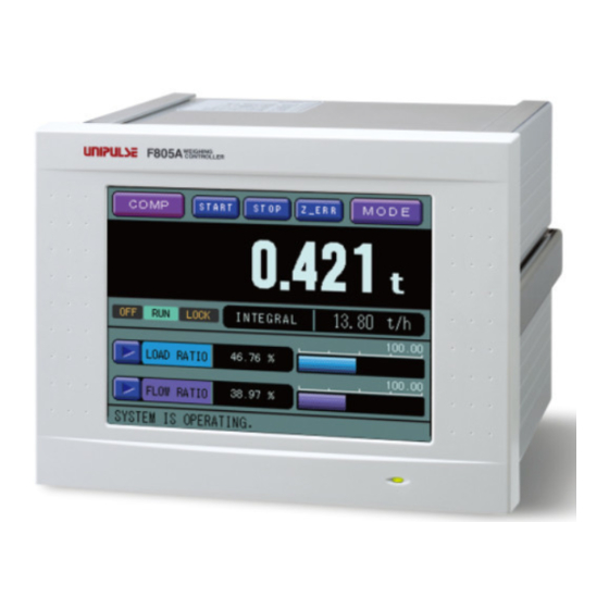
Unipulse F805AT-BC Operation Manual (202 pages)
BELT SCALE CONTROLLER
Brand:
Unipulse
| Category:
Controller
| Size: 2.72 MB
Table of Contents
Table of Contents
7
1.Features of F805At-Bc (Belt Scale Type)
16
Basic Functions
16
Control Functions
16
Master-Slave Functions
17
RS-232C, RS-485 (RS-485 Optional)
18
Current Outputs (2 Channels) and Pulse Input (DAC)
18
Analog Inputs (2 Channels) and Current Outputs (3 Channels) (ANA Optional)
18
BCD Input/Output (BCI and BCO Optional)
18
Upper/Lower Limit Comparison
18
Total Pulse Output (2 Channels)
18
Interface
19
Graphics Display
19
2.Front Panel and Rear Panel
20
Front Panel
20
Rear Panel
21
3.Screen Layouts and Settings
23
Screen Configuration Flow Chart
23
Settings
24
Item Selection
24
Parameter Setting
25
Screens
26
Comparison Screen
26
Message Screen
28
Graph Screen
29
4.Signal Connection
30
Load Cell Connection
31
6-Wire Load Cell Connection
31
4-Wire Load Cell Connection
32
Connecting Load Cells in Parallel
33
Sensor Cable
33
Connecting Power Input Terminal at the DC Spec
34
Connection of the Protective Ground
34
Connecting SI/F
35
Connecting SI/FII
35
External I/O Connector
36
Pin Assignment
36
Equivalent Circuit (Input)
37
Equivalent Circuit (Output)
37
RS-232C Connector
38
Pin Assignment
38
Cable Connection
38
5.Calibration
39
What Is Calibration
39
Actual Load Calibration (Weight Calibration)
40
Secondary Calibration
41
(Calibration Using Equivalent Input) [Weight Calibration]
41
Flow Calibration
43
Preparation for Calibration
44
Releasing the LOCK
44
Weight Calibration
46
Zero Calibration
46
Span Calibration
48
Equivalent Calibration
50
Balance Weight
51
Capacity
51
Minimum Scale Division (Weight)
51
Excitation Voltage
51
Decimal Place (Weight)
52
Gravitational Acceleration
52
Initial Dead Load
53
Settings for Flow Calibration
54
Zero Error Measure
54
Span Error Measure
55
Zero Error Set
55
Span Error Set
55
Test Mode
56
Belt Length
56
Cal Weight Density
56
Rated Weight Density
57
Decimal Place (FLOW)
57
Speed Input Count Meas (DAC Required)
58
Speed Input Count
59
Error Meas.select
59
Min.scale DIV.(FLOW)
60
Z_Error Upper Limit
60
Zero Point Auto Adjustment
60
6.Setting and Adjustment of Reading
61
Operation
61
Weighing Section
61
Rated Feed Rate (FS)
61
Feed Unit
61
Operation Select
62
Rated Belt Speed
62
Dead Band
62
Dead Band Load Ratio
63
Dead Band Belt Speed
63
Moisture Ratio
63
Feed Pulse (W/P) 1
64
Feed Pulse (W/P) 2
64
Pulse Width 1
64
Pulse Width 2
64
Total W. Disp. Digit
65
Alarm Time
65
Start Time, First Stability Time
66
Operation Mode
67
Function
69
Total Weight Clear
69
Start/Stop Key
69
Digital Zero (DZ)
69
Digital Zero Clear
70
Zero Tracking (ZT)
70
DZ Regulation Value
71
Z_ERR Key
71
Weighing Code Selection
71
I/O Monitor Display
72
Communication (RS-232C, SI/F, SI/FII)
73
Baud Rate
73
Character Length
73
Parity Bit
73
Stop Bit
73
Terminator
74
F Output1 Select
74
F Output2 Select
74
Fii ID
75
Comparison
75
Alarm Upper Limit
75
Alarm Lower Limit
76
Alarm Mode
76
Total Final
76
Total Final Mode
77
Belt Speed over
77
Weight Density over
78
Feed Rate over
78
Load Ratio over
78
Feed Ratio over
79
Graph Setting
79
Bar Graph Screen
79
Belt Speed End Point
79
Weight Density End Point
80
Feed Rate End Point
80
Load Ratio End Point
80
Feed Ratio End Point
80
Disp. Data Select 1
81
Disp. Data Select 2
81
Points in Waveform Graphic Display
82
Details of Waveform Display
83
Graphic Mode
86
Trigger Level
86
Trigger CH Select
87
Split Selection
87
Disp. Partition Ch1/Ch2/Ch3
87
Ch1/Ch2/Ch3 Start Point
88
Ch1/Ch2/Ch3 End Point
88
End Point
88
Display
89
Display Frequency
89
Digital Filter
89
Analog Filter
89
Average Count
90
Error Display Control
90
Data Select Key
90
Disp Data Selection
91
Control Parameter
91
Target Set
91
Control Limit
92
Allowable Control Dev
92
Rate Limit
92
Fault Detect Value
93
Master/Slave Select
93
Slave Mode Select
93
Start/Error Display
94
Flow Stability Time
94
Start Coordin. Value
95
Control Frequency
96
Each Code
96
How to Assign Code
97
PID Control
97
AT Coordin Time, at Coordinate 1 -4, at Coordin out 1 -4
100
States Ascertain
101
Belt Speed over Asc
101
Weight Density over Asc
101
Feed Rate over Asc
102
Load Ratio over Asc
102
Feed Ratio over Asc
103
Deviation Lim. over Asc
103
System
104
Back Light Auto. Light
104
Back Light Low Time
104
Back Light on Time
104
Lock(Soft
105
Self Check
105
Language
109
Pass Word
109
7.CONTROL SIGNAL (External I/O Connector)
110
Pin Assignment
110
Equivalent Circuit (Input)
111
Equivalent Circuit (Output)
111
External Input Signal
112
Running (Edge Input)
112
Display 1 Change (Level Input)
112
Display 2 Change (Level Input)
112
Total Weight Clear (Edge Input)
113
Digital Zero (Edge Input)
113
Zero Point Auto Adjustment (Edge Input)
113
Test Mode Span Measurement (Edge Input)
114
Pulse Count Start (Edge Input)
114
Pulse Count Stop (Edge Input)
114
Operation Mode (Level Input)
115
Graph Drawing (Edge Input)
115
Code # Designation (Level Input)
115
External Output Signal
116
Pulse Output 1
116
Pulse Output 2
116
Upper Limit (HI)
116
Lower Limit (LO)
116
Weight Error
116
Belt Moving
116
Power on
116
Running
117
Total Final over
117
Zero Error Measuring
117
Zero Error Measure OK
117
Zero Error Measure NG
117
8.Interface
118
2-Wire Serial Interface SI/F
118
2-Wire High-Speed Bi-Directional Serial Interface SI/F II
119
RS-232C Interface
120
Communication Specifications
120
Settings for RS-232C
121
Cables
121
Communication Format
122
D/A Converter [DAC]
139
External Output Port
139
D/A Output Channel
141
D/A Output Mode
141
D/A Zero Output Weight
141
D/A Full Scale
142
D/A Output Compensation
142
D/A Lower Limit
143
D/A Upper Limit
143
Speed Entry Select
144
Pulse Count/Rotation
144
Fine-Adjustment of D/A Converter
144
Pulse Input Entry Procedure
146
9.OPTION (Option Card Required)
147
BCD Parallel Output Interface [BCO]
147
Connector Pin Assignments
147
Equivalent Circuit (Output)
148
Equivalent Circuit (Input)
148
BCD Data Output
148
Polarity Output (MUNUS)
149
Over Status Output (OVER)
149
Data Strobe (STROBE)
149
Hold Input
149
Logic Toggling Input
149
Output Selection Input
150
BCD out Setting
150
BCD Parallel Data Input Interface [BCI]
151
Connector Pin Assignment (BCD INPUT)
151
Equivalent Circuit
151
Two Reading Modes
151
Level Input Mode (STROBE Short-Circuited)
152
Edge Input Mode
152
Data Code (23, 24, 25 Pin)
152
Analog IN/OUT [ANA]
153
External Output Port
154
AO Channel Select
155
AO Output Mode
155
AO Zero Output Weight
156
AO Full Scale Value
156
AO Output Compensation
156
AO Lower Limit
157
AO Upper Limit
157
Fine Adjustment of Current Output
158
Current Input Select
159
AI Input Channel
159
AI Zero Set
160
AI Full Scale Set
160
AI Digital Filter
161
Target Entry Select
161
AI Target Value
162
AI Min. Scale DIV
162
Speed Entry Select
162
Interface [485]
163
Communication Specifications
163
One to One Connection
163
One to Multi Connection
164
Settings for RS-485
164
How to Communicate
164
Communication Format
165
10.Arithmetics
166
Belt Speed [M/Min]
166
Weight Density [Kg/M]
167
Feed Rate ([Kg/H], [T/H])
168
Load Ratio [%]
168
Feed Ratio [%]
168
Total ([Kg/H], [T/H])
169
Standard Feed Weight [Kg]
169
Error Measure
170
Compensation
170
Equivalent Target ([Kg/H], [T/H])
170
Initial Control Rate
171
Control Deviation
171
11.Troubleshooting
172
Running-Down Lithium Battery
172
Over Scale Display
173
Calibration Error Display
174
Sequence Error Display
174
ANA Error Display
175
Priority for Error Display
175
Over Scale Display
176
Sequence Error
178
Calibration Error
180
ANA Error (Analog IN/OUT Interface Required)
182
12.Block Diagram
183
13.Dimensions
184
14.Mounting on a Panel
185
15.Specifications
186
Analog
186
Display
186
Setting
187
External I/O
187
Interface
187
General
190
Accessory and Parts
191
16.Setting Items List
192
17. Setting Mode Tree Chart
199
18.Statement of Conformation to Ec Directives
200
(Designated When It Is Shipped)
200
Advertisement
Advertisement
Related Products
Unipulse F805AT-CK
Unipulse F600AT
Unipulse F701
Unipulse F156
Unipulse F160
Unipulse DeviceNet F381A
Unipulse F331
Unipulse F320
Unipulse F377A
Unipulse F701+
Unipulse Categories
Measuring Instruments
Touch Panel
Controller
Monitor
Accessories
More Unipulse Manuals
Login
Sign In
OR
Sign in with Facebook
Sign in with Google
Upload manual
Upload from disk
Upload from URL