Sign In
Upload
Manuals
Brands
Unipulse Manuals
Touch Panel
F331
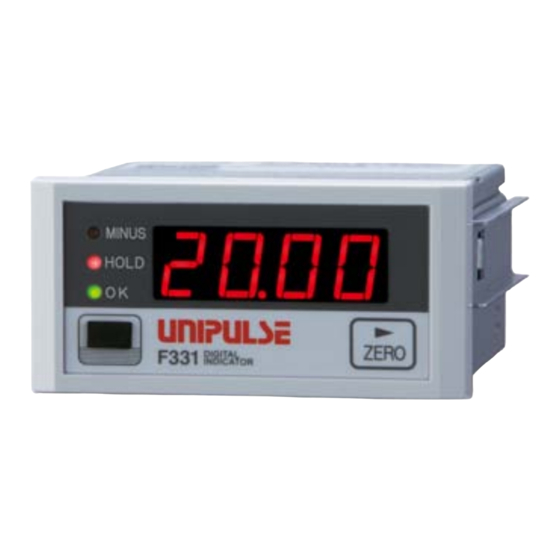
Unipulse F331 Digital Indicator Manuals
Manuals and User Guides for Unipulse F331 Digital Indicator. We have
1
Unipulse F331 Digital Indicator manual available for free PDF download: Operation Manual
Unipulse F331 Operation Manual (88 pages)
Digital indicator
Brand:
Unipulse
| Category:
Touch Panel
| Size: 1 MB
Table of Contents
Table of Contents
7
1 Outline
10
Contents of the Package
10
About Connectable Devices
10
Appearance Description
11
Front Panel
11
Rear Panel
12
2 Connection
14
Connection of the Signal Input/Output Terminal Block
15
Connection of the Strain Gauge Sensor
16
4-Wire Strain Gauge Sensor
16
Connection of the Power Input Terminal
17
Connection of the Protective Ground
17
Connection of the External Output (Sink Type)
18
Connection of the External Input
18
3 Setting Method
19
Preparation of PC
19
PC Hardware Requirement
19
Installation of a USB Driver
19
Connection of USB
19
The Check of a Virtual COM Port
19
Starting of the F331 PC Application Software
19
Installation of the F331 PC Application Software
19
The Injection of a Power Supply
20
Starting of the F331 PC Application Software
20
Specification of a COM Port
20
The Check of a Indicating Value
20
List of Setting Values
21
Comparison Setting
21
Operation Setting
21
Calibration Setting
21
Option Setting
22
Setting Procedure
22
4 How to Calibration
23
Equivalent Input Calibration Procedure
24
Actual Load Calibration Procedure
24
Decimal Place
24
Equipment ID
24
5 Setting of Functions
25
HI-LO Limit Comparison
25
Hysteresis
26
Near Zero
27
Comparison Timing
27
Digital Offset
27
Moving Average Filter
27
Digital Low Pass Filter
27
Hold Mode
28
Sample (the Arbitrary Points Are Held.)
28
Peak (the Maximum Point Is Held.)
28
Bottom (the Minimum Point Is Held.)
29
P-P (the Difference of the Maximum Point and the Minimum Point Is Held.)
29
Digital Zero Function
30
Digital Zero by Key Operation
30
Digital Zero by External Signal Input
30
5-10.ZERO Key Valid/Invalid
30
5-11.Display Frequency
30
6 External Input/Output Signals
31
Connector Pin Assignments
31
External Input Signals
31
Hold/Judge <Edge Input
31
Digital Zero <Edge Input
31
External Output Signals
32
External Output Selection
32
Ok/ Ng/ Hh/ Hi/ Lo/ Ll
32
BCD Data Output
33
7 Option
33
Equivalent Circuit
34
Connector Pin Assignment
35
BCD Output Mode
36
BCD Data Update Rate Selection
36
BCD External Output Selection
36
D/A Converter
37
Current Output (DAI Option)
37
D/A Zero and Full Scale
39
D/A Output Mode
39
RS-485 Interface
40
Communication Specifications
40
RS-485 Connection
41
RS-485-Related Setting Values
42
UNI-Format Commands
43
UNI-Format (Continuous)
48
Modbus-RTU
48
Setting Value LOCK/ Calibration Value LOCK
66
RS-232C Interface
67
Communication Specifications
67
Cable
67
RS-232C-Related Setting Values
68
Command Communication Formats
69
Setting Value Communication Formats
72
Continuous Transmission Formats
74
Setting Value LOCK/ Calibration Value LOCK
74
8 Specifications
75
Analog Section
75
Display Section
75
Setting Section
75
External Signals
76
Interface
76
General Specifications
78
Accessories
78
Dimensions
79
When the BCD Output Option Is Equipped
80
When the D/A Converter Option Is Equipped
81
When the RS-485 Option Is Equipped
82
When the RS-232C Option Is Equipped
83
Mounting on a Panel
84
Block Diagram
85
9 Supplements
86
Error / Message Display
86
Over Scale Display
86
Calibration Error Display
86
Message Display
86
Self-Check/Initialization
87
Self-Check (at Power-On)
87
Self-Check (When PC Application Is Activating)
87
Initialization (When PC Application Is Activating)
87
Advertisement
Advertisement
Related Products
Unipulse DeviceNet F381A
Unipulse F340A
Unipulse DeviceNet F388A
Unipulse F372A
Unipulse F350
Unipulse f395
Unipulse F370
Unipulse F371
Unipulse F325
Unipulse F320
Unipulse Categories
Measuring Instruments
Touch Panel
Controller
Monitor
Accessories
More Unipulse Manuals
Login
Sign In
OR
Sign in with Facebook
Sign in with Google
Upload manual
Upload from disk
Upload from URL