Table of Contents
Advertisement
Quick Links
Advertisement
Table of Contents

Related Manuals for Unipulse F805AT-BC


Summary of Contents for Unipulse F805AT-BC
- Page 1 F805AT-BC BELT SCALE CONTROLLER OPERATION MANUAL 15 Feb. 2019 Rev. 1.03...
- Page 2 Safety Precaution For safety reasons, please read the following safety precautions thoroughly. In order to have an F805AT-BC used safely, notes we would like you to surely follow divide into " " and "...
- Page 3 - Use greatly impacting human lives and assets, such as medical devices, transport devices entertainment devices, and safety devices. Warning on installation ● Do not disassemble, repair, or modify the F805AT-BC. Doing so may cause a fire or an electric shock. ● Do not install in the following environments.
- Page 4 - Where a strong electric field or magnetic field is formed. - Where static electricity, relay noise or the like is generated. ● Install the F805AT-BC as far away from devices generating high frequency, high voltage, large current, surge, etc., as possible. Also, carry out wiring separately from their power lines.
- Page 5 Caution during startup and maintenance ● For turning on/off the power, be sure to keep intervals of 5 seconds or more. ● After power-on, make sure to warm up the F805AT-BC for at least 30 minutes or more before use.
- Page 6 RoHS-compliant product RoHS-compliant product The parts and attachments (including the instruction manual, packaging box, etc.) used for this unit are compliant with the RoHS Directive restricting the use of hazardous substances with regard to adverse effects on the environment and human body. Please inquire of our sales person about the RoHS-compliance of the option.
-
Page 7: Table Of Contents
CONTENTS CONTENTS 1.FEATURES OF F805AT-BC (BELT SCALE TYPE) ....1 1-1.Basic Functions ..................1 1-2.Control Functions ................. 1 1-3.Master-Slave Functions ............... 2 1-4.RS-232C, RS-485 (RS-485 optional) ............ 3 1-5.Current Outputs (2 channels) and Pulse Input (DAC) ....... 3 1-6.Analog Inputs (2 channels) and Current Outputs (3 channels) (ANA optional) .................. - Page 8 CONTENTS 4-1-4.Sensor cable .................... 18 4-2.Connecting power input terminal at the DC Spec......19 4-3.Connection of the protective ground ..........19 4-4.Connecting SI/F .................. 20 4-5.Connecting SI/FII ................20 4-6.External I/O Connector ............... 21 4-6-1.Pin assignment ..................21 4-6-2.Equivalent circuit (input) ................ 22 4-6-3.Equivalent circuit (output) ..............
- Page 9 CONTENTS 5-7-9.Decimal place (FLOW) ................42 5-7-10.Speed input count meas (DAC required) ..........43 5-7-11.Speed input count ................. 44 5-7-12.Error meas.select .................. 44 5-7-13.Min.scale div.(FLOW) ................45 5-7-14.Z_error upper limit ................. 45 5-7-15.Zero point auto adjustment ..............45 6.SETTING AND ADJUSTMENT OF READING .....46 6-1.Operation .....................
- Page 10 CONTENTS 6-4-2.Alarm lower limit ..................61 6-4-3.Alarm mode ....................61 6-4-4.Total final ....................61 6-4-5.Total final mode ..................62 6-4-6.Belt speed over ..................62 6-4-7.Weight density over ................63 6-4-8.Feed rate over ..................63 6-4-9.Load ratio over ..................63 6-4-10.Feed ratio over ..................64 6-5.Graph Setting ..................
- Page 11 CONTENTS 6-8-1.How to assign code ................. 82 6-8-2.PID control ....................82 6-8-3.AT coordin time, AT coordinate 1 –4, AT coordin out 1 -4 ....85 6-9.States Ascertain .................. 86 6-9-1.Belt speed over asc................. 86 6-9-2.Weight density over asc................. 86 6-9-3.Feed rate over asc.
- Page 12 CONTENTS 7-5-10.NZ ......................102 7-5-11.Total final over ..................102 7-5-12.Zero error measuring ................102 7-5-13.Zero error measure OK ............... 102 7-5-14.Zero error measure NG ............... 102 8.INTERFACE ................103 8-1.2-Wire Serial Interface SI/F .............. 103 8-2.2-Wire High-Speed Bi-Directional Serial Interface SI/F II ....104 8-3.RS-232C Interface ................
- Page 13 CONTENTS 9-2-5.Edge input mode ................... 137 9-2-6.Data code (23, 24, 25 pin) ..............137 9-3.Analog IN/OUT [ANA] ............... 138 9-3-1.External output port ................139 9-3-2.AO channel select ................. 140 9-3-3.AO output mode ..................140 9-3-4.AO zero output weight ................141 9-3-5.AO full scale value .................
- Page 14 CONTENTS 11.TROUBLESHOOTING ............157 11-1.Running-down Lithium Battery ............. 157 11-2.Over Scale Display ................. 158 11-3.Calibration Error Display ............... 159 11-4.Sequence Error Display ..............159 11-5.ANA Error Display ................160 11-6.Priority for Error Display ..............160 11-7.Over Scale Display ................. 161 11-8.Sequence Error ................163 11-9.Calibration Error ................
- Page 15 CONTENTS M E M O...
-
Page 16: 1.Features Of F805At-Bc (Belt Scale Type)
1. FEATURES OF F805AT-BC (BELT SCALE TYPE) 1-1. Basic Functions F805AT-BC (Belt scale type) provides accurate metering of materials while they are being conveyed on the belt conveyer. Using weight signal from the load cell and velocity signal from the speed sensor installed on the conveyer system, the following data items can be obtained through mathematical calculations: ①... -
Page 17: Master-Slave Functions
As shown in the figures, two or more of F805AT-BCs can be configured to operate in a master-slave mode, in which one F805AT-BC functions as a master and others as slaves. The slaves operate following the target values and flow set by the master device. -
Page 18: Rs-232C, Rs-485 (Rs-485 Optional)
1.FEATURES OF F805AT-BC (BELT SCALE TYPE) 1-4. RS-232C, RS-485 (RS-485 optional) Most of the set values, and most of the calculation results and device status information can be read/written using the serial communication. 1-5. Current Outputs (2 channels) and Pulse Input (DAC) -
Page 19: Interface
The user can configure full-scale values for each item. F805AT-BC also provides a waveform display, in which input signals waveforms are shown graphically. This mode can display belt speed, weight density, feed rate, load ratio, feed ratio, and control rate. -
Page 20: 2.Front Panel And Rear Panel
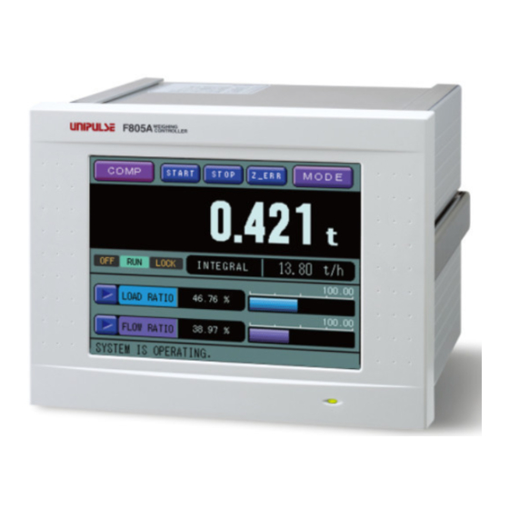
This touch-screen display is used for dual purposes: display of readings/graphs, and to input/edit configuration parameters. Power lamp The light is on, when the F805AT-BC is turned on. It remains on even if the device is in sleep mode (display blacks out). -
Page 21: Rear Panel
2.FRONT PANEL AND REAR PANEL 2-2. Rear Panel ④ Option slot ⑩ Load cell ① AC power input connector connector ② Frame ground ⑨ SI/F terminal block ⑤ RS-232C connector ⑧ SI/FII terminal block ⑥ LOCK switch ⑦ Control signal Input / Output connector *DC spec.(Designated when it is shipped) Red (plus) - Page 22 9. SI/F terminal block Serial interface (SI/F) terminal block used for connecting external devices such as the dedicated UNIPULSE printer, external display, and data converter. 10. Load cell connector Plug the supplied load cell connector. Compatible plug is HIROSE JR16PN-7S...
-
Page 23: 3.Screen Layouts And Settings
3.SCREEN LAYOUTS AND SETTINGS 3. SCREEN LAYOUTS AND SETTINGS 3-1. Screen Configuration Flow Chart Graph 【Main screen】 COMP MESSAGE [Comparison screen] [Message screen] [Graph screen (Bar graph) ] MODE BACK GRAPH GRAPH TYPE TYPE 【Operation mode screen】 [Graph screen (Waveform) ] to Main screen Mode 【Setting value input screen】... -
Page 24: Settings
3.SCREEN LAYOUTS AND SETTINGS 3-2. Settings 3-2-1. Item selection In this manual, the steps required to select an item is shown in the following format. (Example) To specify a setting item associating the X (time)-axis end point. MODE GRAPH SETTING →... -
Page 25: Parameter Setting
3.SCREEN LAYOUTS AND SETTINGS 3-2-2. Parameter setting (Example 1) Setting by selecting displayed items: To select “16 times” for digital filter. Selected value Options 1)Press one of the option buttons ( in this case) 16 Times 2)Check that the selected value appears on the top line. 3)Press to confirm. -
Page 26: Screens
3.SCREEN LAYOUTS AND SETTINGS 3-3. Screens 3-3-1. Comparison screen One of the two important arithmetic values (Total and Feed rate) is displayed in large digits for easy monitoring, and the other one of the two is displayed in smaller digits beneath it accompanied with status lamps. - Page 27 3.SCREEN LAYOUTS AND SETTINGS Status display Lock This lamp turns on when settings are locked: ・ LOCK (hard) is ON: is displayed in reversed red. LOCK ・ LOCK (soft) is ON: is displayed in reversed orange. LOCK LOCK (hard) has the priority over LOCK (soft) Run/NOV.RAM/DZ Warning/Flow Setting Over/Flow Setting Under is displayed in reversed light blue while TOTAL measurement is being performed.
-
Page 28: Message Screen
3.SCREEN LAYOUTS AND SETTINGS Data display This field displays selected two items in numerical and bar graph format. Selectable data items are: belt speed, weight density, feed rate, load ratio, feed ratio, gross weight, control rate, and control deviation. Simply push button to switch the display item, or use external signal to change data. -
Page 29: Graph Screen
3.SCREEN LAYOUTS AND SETTINGS 3-3-3. Graph screen Arithmetic values selected from belt speed, weight density, feed rate, load ratio, feed ratio, and control rate are displayed either in bar graph or analog waveform. One of the two graph formats is arbitrary chosen by pressing GRAPH TYPE . -
Page 30: 4.Signal Connection
4.SIGNAL CONNECTION 4. SIGNAL CONNECTION Precautions about connection to the signal input/output terminal block are given below. The precautions described here are important for safety. Please properly understand the descriptions before connection. WARNING ● Do not connect a commercial power source directly to the signal input/output terminals. -
Page 31: Load Cell Connection
4.SIGNAL CONNECTION 4-1. Load Cell Connection The load cell connector used by F805AT-BC is HIROSE JR16PN-7S (supplied) or its equivalent. Voltage value used to excite the load cell is either 5 or 10 volts (selectable), and max. current is 120mA. -
Page 32: 4-Wire Load Cell Connection
(class A). If it is used in a housing environment, interference may be caused. In that case, take appropriate measures. ● The load cell excitation voltage of the F805AT-BC is 5V or 10V. Heating or breakage may occur unless the load cells maximum excitation voltage is the load cell excita- tion voltage of the F805AT-BC or more. -
Page 33: Connecting Load Cells In Parallel
4.SIGNAL CONNECTION 4-1-3. Connecting load cells in parallel Some industrial measurement application use multiple of load cells connected in parallel. An example of parallel connection is shown below: As seen from the instrument, n +EXC load cells connected in parallel -SIG behave as if they constitute a single -EXC... -
Page 34: Connecting Power Input Terminal At The Dc Spec
For use at voltages exceeding the rating and for overseas use, have a separate AC cable prepared. ● Since the F805AT-BC has no power switch, install a breaker. ● Be sure to ground the protective ground terminal to prevent electric shocks. -
Page 35: Connecting Si/F
SI/F interface uses a cage clamp terminal block. Step by step connection procedures are described below (use a mini-driver that comes standard with F805AT-BC). 5-6 mm 1) Strip cable sheath by 5-6mm off the top of the cable. -
Page 36: External I/O Connector
4.SIGNAL CONNECTION 4-6. External I/O Connector F805AT-BC uses a 50-pin amphenol connector for the external I/O connector. Compatible plug is DKK 57-30500 (supplied) or its equivalent. For more information, "CONTROL SIGNAL (External I/O Connector)" , on page 95. 4-6-1. Pin assignment *... -
Page 37: Equivalent Circuit (Input)
Signal input is performed by closing and opening the input terminals, namely between the input terminal and COM. Contact devices (such as relay and switch) and non- contact devices (such as transistor, open-collector TTL) can be used for this purpose. Open F805AT-BC Close +12V inside... -
Page 38: Rs-232C Connector
PC connector (25-pin) cross cable The wiring diagram shown above is used for connecting the F805AT-BC to a DTE (data terminal device). Usually a PC functions as a DTE. If you connect it to a DCE (data circuit terminating equipment) such as a modem, use a straight cable. -
Page 39: 5.Calibration
5. CALIBRATION 5-1. What is calibration? Calibration represents a set of procedure to verify that the F805AT-BC is correctly adjusted so that it can receive information from the load cell properly. When 100kg of real load is applied to the weighing part (load cell) of a metering device, the indicator connected to the weighing device, if it is properly calibrated, should recognize the data as accurate as possible (e.g. -
Page 40: Actual Load Calibration (Weight Calibration)
5.CALIBRATION 5-2. Actual Load Calibration (Weight Calibration) Step by step procedures for actual load calibration are as follows: Toggle the LOCK switch on the rear panel to OFF LOCK(hard) OFF position to enable calibration. Remove software LOCK to enable calibration. LOCK(soft) OFF Select load cell excitation voltage (5 or 10V). -
Page 41: Secondary Calibration
5.CALIBRATION 5-3. Secondary Calibration (Calibration using equivalent input) [Weight calibration] Calibration can be carried out using key input, without actual measurement of the load cell’s rated output (mV/V) and rated capacity (e.g. the value you want to display). This method enables calibration without balance weight, and is useful if the instrument is replaced due to failure, or incorrect span calibration is found. - Page 42 5.CALIBRATION Note The value of balance weight should be less than the instruments capacity. If you use rated value written in the load cell’s specification sheet, use the load cell’s rated value for capacity setting. Parallel connection of multiple load cells can, depending on connection scheme, cause small voltage drop due to lead wires.
-
Page 43: Flow Calibration
5.CALIBRATION 5-4. Flow Calibration Steps for flow calibration are as follows: Toggle the LOCK switch on the rear panel to OFF LOCK(hard) OFF position to enable calibration. Remove software LOCK to enable calibration. LOCK(soft) OFF Select the unit for feed calculation Feed Unit Select decimal place (same setting is used for flow). -
Page 44: Preparation For Calibration
5-5. Preparation for Calibration 5-5-1. Releasing the LOCK F805AT-BC provides two types of lock capabilities to prevent unauthorized or accidental alteration of calibration or set data: you can either lock the instrument by front panel operation ([LOCK (soft)]), or by toggling a rear panel switch ([LOCK (hard)]). - Page 45 5.CALIBRATION After calibration has been completed, be sure to lock the instrument again to protect calibration information. Note See "SETTING ITEMS LIST" , on page 177 for the parameters protected by the LOCK function.
-
Page 46: Weight Calibration
5.CALIBRATION 5-6. Weight Calibration 5-6-1. Zero calibration Zero calibration tunes the instrument’s zero point. Check the weighing device (load cell) and make sure no load is applied to the sensor. A foreign matter placed on the load cell or contact to a foreign object can interfere the calibration. - Page 47 5.CALIBRATION When zero calibration is finished, the instrument will beep and indicator 3) CALZ changes to CALZ flickers while zero calibration is running Calibration data is stored in non-volatile RAM: allow about 30 seconds before you 4) can turn off the instrument indicator comes on in reversed display while writing data to RAM, then the indicator changes to See "TROUBLESHOOTING"...
-
Page 48: Span Calibration
5.CALIBRATION 5-6-2. Span calibration Span calibration adjusts the instrument’s span (gain) parameters by placing a known weight on the load cell. Enter the known weight value to BALANCE WEIGHT field. To obtain a good linearity, use of a weight heavier than 50% Capacity is recommended. Before performing calibration, make sure unwanted load is applied to the load cell (See “Zero calibration”). - Page 49 5.CALIBRATION 4)Calibration data is stored in non-volatile RAM: allow about 30 seconds before you can turn off the instrument indicator comes on in reversed display while writing data to RAM, then the indicator changes to See "TROUBLESHOOTING" , on page 157 for the details of calibration errors.
-
Page 50: Equivalent Calibration
5.CALIBRATION 5-6-3. Equivalent calibration Enter and store the load cell’s rated output (mV/V) and the rated capacity value (e.g. the value you want to be displayed). Enter the rated capacity vale to [BALANCE WEIGHT] field. Enter the rated output (mV/V) for the load cell. Make sure that indicator is off. -
Page 51: Balance Weight
5.CALIBRATION 5-6-4. Balance weight Enter the value of balance weight that is used (actually applied to the load cell) in span calibration. Operation MODE WEI.CALIBRATION → BALANCE WEIGHT → Input range: 0 – 99999 (5 digits, decimal point is automatically set) 5-6-5. -
Page 52: Decimal Place (Weight)
5.CALIBRATION 5-6-8. Decimal place (weight) Define the data representation format (decimal point place) for the measurement items that are defined as variable digits. See "SETTING ITEMS LIST" , on page 177 for further information. Operation MODE WEI.CALIBRATION PAGE → DECIMAL PLACE(WEIGHT) →... -
Page 53: Initial Dead Load
5.CALIBRATION 5-6-10. Initial dead load Enter and store the initial zero point by value. Register the load cell’s initial dead load (mV/V). Make sure that indicator is off and follow the same steps described in “Equivalent calibration”. Operation Press [INITIAL DEAD LOAD] 1)... -
Page 54: Settings For Flow Calibration
5.CALIBRATION 5-7. Settings for Flow Calibration 5-7-1. Zero error measure This function measures the Zero-error point. This function takes measurements disregarding the current [ZERO ERROR SET] setting (e.g. assuming that it is set to 0%). You can define multiple, up to three, starting points on the conveyer (see the figure below) and take measurements simultaneously and independently to each other. -
Page 55: Span Error Measure
5.CALIBRATION 5-7-2. Span error measure A function to measure span error point. This function takes measurements disregarding the current [SPAN ERROR SET] setting (e.g. assuming that it is set to 0%). As in the case with “Zero error measurement”, up to three independent reference points can be defined on the conveyer and allows simultaneous measurements. -
Page 56: Test Mode
5.CALIBRATION 5-7-5. Test mode This function performs error measurement using the set values from [ZERO ERROR SET] and [SPAN ERROR SET]. From the current (old) error value and newly obtained error value, the error value is calculated and updated using the following equation. New error value = old error value + newly obtained error value Press to register the new value to your instrument. -
Page 57: Rated Weight Density
5.CALIBRATION 5-7-8. Rated weight density This function specifies the rated weight density [kg/m] of the belt scale. Operation MODE FLOW CALIBRATION PAGE → RATED WEIGHT DENSITY → → Range: 0.001 – 9999 kg/m (4 digits, arbitrary decimal point) 5-7-9. Decimal place (FLOW) This function specifies decimal point places for those set values and calculated values whose decimal place changes in according with the flow value. -
Page 58: Speed Input Count Meas (Dac Required)
5.CALIBRATION 5-7-10. Speed input count meas (DAC required) This function either counts pulses from the velocity detector (NORMAL MODE) or measures rotations of the rotary encoder (PHASE MEASURE). Using this function, you can determine the numerical relationship between belt’s travel and the pulse count (distance of belt progress per a pulse), or rotations of the rotary encoder (distance of belt progress per a rotation). -
Page 59: Speed Input Count
5.CALIBRATION 5-7-11. Speed input count When “NORMAL MODE A”, “NORMAL MODE B”, “NORMAL A SLOW”, “ANA. NORMAL A”, or “ANA. A SLOW” is selected in [SPEED ENTRY SELECT], specify a pulse count (9-digit integer) that represents the travel length of the belt (BELT LENGTH). -
Page 60: Min.scale Div.(Flow)
5.CALIBRATION 5-7-13. Min.scale div.(FLOW) This function specifies the minimum measurement division (scale interval) for belt speed, feed rate, and feed ratio. Operation MODE FLOW CALIBRATION PAGE → MIN.SCALE DIV.(FLOW) → → Range: 1 – 100 (3 digits, decimal point moveable) 5-7-14. -
Page 61: 6.Setting And Adjustment Of Reading
6.SETTING AND ADJUSTMENT OF READING 6. SETTING AND ADJUSTMENT OF READING 6-1. Operation 6-1-1. Weighing section This function specifies the weighing section length in millimeter. The weighing section represents the effective length of the portion of the belt that carries measured materials whose weight is detected by the weighing sensor. -
Page 62: Operation Select
6.SETTING AND ADJUSTMENT OF READING 6-1-4. Operation select Depending on the option selected in this field, the system’s STAR/STOP is controlled either by internal (touch-panel key) or external input. Auto-resume function (restore states and resume operation after a power failure) can only be enabled when internal input is selected. -
Page 63: Dead Band Load Ratio
While the value of DEAD BAND LOAD RATIO (%) is greater than LOAD RATIO (%), F805AT-BC turns on “NZ” status indicator and set the NZ external signal to “ON”. Accumulation is not performed in this state. Setting DEAD BAND LOAD RATIO to zero disables accumulation calculation. -
Page 64: Feed Pulse (W/P) 1
6.SETTING AND ADJUSTMENT OF READING 6-1-10. Feed pulse (W/P) 1 This parameter defines weight value per one pulse of PULSE OUTPUT1. Operation MODE OPERATION PAGE → FEED PULSE (W/P)1 → → Options: 100g, 1kg, 10kg, 100kg, 1t 6-1-11. Feed pulse (W/P) 2 This parameter defines weight value per one pulse of PULSE OUTPUT2. -
Page 65: Total W. Disp. Digit
6.SETTING AND ADJUSTMENT OF READING 6-1-14. Total W. disp. digit This parameter defines the unit for TOTAL W.DISP.DIGIT. Operation MODE → OPERATION → PAGE → TOTAL W DISP.DIGIT Options: 1g or 1kg, 10g or 10kg, 100g or 100kg, 1kg or 1t 6-1-15. -
Page 66: Start Time, First Stability Time
6.SETTING AND ADJUSTMENT OF READING 6-1-16. Start time, First stability time Feed rate Target value PID control starts Time Start time First stability time When the operation starts, control rate linearly increases up to its initial set value until the start time expires. Following this, the system enters into idling mode until the first stability time expires (During idling mode operation, control rate is LOCKed and weight data are not sampled. -
Page 67: Operation Mode
6.SETTING AND ADJUSTMENT OF READING 6-1-17. Operation mode ● Continued feed rate This mode controls the system so as to maintain constant flow (Feed Rate). Target feed rate value is specified using t/h or kg/h unit depending on the [FEED UNIT] setting. Feed rate ([kg/h], [t/h]) Actual feed rate Step change in target value... - Page 68 [FEED UNIT], specify the target feed rate value in t/h or kg/h. If you change the target value or clear the TOTAL, F805AT-BC starts from that point in time to control the system so that the ratio is kept constant.
-
Page 69: Function
6.SETTING AND ADJUSTMENT OF READING 6-2. Function 6-2-1. Total weight clear This function clears the Total Weight (this function is disabled while the system is running). Operation MODE FUNCTION TOTAL WEIGHT CLEAR → → Options: NO, YES 6-2-2. Start/Stop key This function enables/disables START STOP... -
Page 70: Digital Zero Clear
6.SETTING AND ADJUSTMENT OF READING 6-2-4. Digital zero clear This function clears the value set to Digital Zero. Performing this function while is in reverse-display (red), the Digital Zero value is cleared and goes ZALM ZALM off. Operation MODE PAGE →... -
Page 71: Dz Regulation Value
6.SETTING AND ADJUSTMENT OF READING 6-2-6. DZ regulation value This value specifies the allowable range of zero-point correction (deviation from zero- calibration), which is referenced by [DIGITAL ZERO] and Zero Tracking function. Performing Digital Zero operation or Zero tracking outside the range, comes on ZALM in reverse-display (red) to notify the abnormal condition. -
Page 72: I/O Monitor Display
6.SETTING AND ADJUSTMENT OF READING 6-2-9. I/O monitor display The view as popup which can monitor the operation state of an external I/O signal by pushing a specific domain is performed. Select Effect or inhibit. - INHIBIT..... A view as popup is not performed. - EFFECT ..... -
Page 73: Communication (Rs-232C, Si/F, Si/Fii)
6.SETTING AND ADJUSTMENT OF READING 6-3. Communication (RS-232C, SI/F, SI/FII) 6-3-1. Baud rate Use this menu item to select baud rate (signal transmission velocity) for RS-232C port. Operation MODE → PAGE → COMMUNICATION → BAUD RATE Options: 1200bps, 2400bps, 4800bps, 9600bps, 19200bps, 38400bps 6-3-2. -
Page 74: Terminator
6.SETTING AND ADJUSTMENT OF READING 6-3-5. Terminator Use this menu item to select which terminator to use with RS-232C. Operation MODE PAGE → COMMUNICATION TERMINATOR → → Options: CR, CR+LF 6-3-6. SI/F output1 select Use this menu item to select the data 1 to send out via SI/F. Operation MODE PAGE →... -
Page 75: Fii Id
Up to eight F805AT-BCs can be connected in SI/FII network, up to four of them can be operate as masters. They are grouped together using the ID (see the figure below) to form up to four groups. ID =0 ID =1 ID =2 ID =3 F805AT-BC F805AT-BC F805AT-BC F805AT-BC Master Master Master... -
Page 76: Alarm Lower Limit
6.SETTING AND ADJUSTMENT OF READING 6-4-2. Alarm lower limit alarm lamp comes on if the item set in [ALARM MODE] falls short of this set value ( is displayed in reversed red while RUNNING), and the external output LO turns ON. This value is ignored if “COMPARISON OFF”... -
Page 77: Total Final Mode
6.SETTING AND ADJUSTMENT OF READING [Main arithmetic display: TOTAL] [Main arithmetic display: FEED RATE] 6-4-5. Total final mode Use this menu item to select if the Total Final value is to be compared with the set values. COMPARISON OFF: comparison with [TOTAL FINAL] set value is disabled. ALARM&CONTINUE: the run continues if TOTAL FINAL OVER occurs. -
Page 78: Weight Density Over
6.SETTING AND ADJUSTMENT OF READING 6-4-7. Weight density over Over scale alarm “OFL2” is activated when weight density becomes greater than WEIGHT DENSITY OVER set value. Comparison is disabled if the value is set to 99999. Also, the comparison is disabled if [WEIGHT DENSITY OVER OVER ASC.] is set to zero second. -
Page 79: Feed Ratio Over
6.SETTING AND ADJUSTMENT OF READING 6-4-10. Feed ratio over Over scale alarm “OFL5” is activated when the feed ratio becomes greater than FEED RATIO OVER set value. Comparison is disabled if the value is set to 999.99. Also, the comparison is disabled if [FEED RATIO OVER ASC.] is set to zero second. Operation MODE →... -
Page 80: Weight Density End Point
6.SETTING AND ADJUSTMENT OF READING 6-5-3. Weight density end point Use this item to specify the full-scale value for weight density bar graph. Operation MODE GRAPH SETTING → WEI DENS END POINT → Range: 1 – 99999 kg/m (5 digits, decimal place floating) 6-5-4. -
Page 81: Disp. Data Select 1
6.SETTING AND ADJUSTMENT OF READING 6-5-7. Disp. data select 1 Use this menu item to select data to be displayed in the upper part of comparison screen. Selecting “EXTERNAL ENTRY” in this menu enable an external signal to select data. (3-5 pins of external I/O connector). Operation MODE →... -
Page 82: Points In Waveform Graphic Display
6.SETTING AND ADJUSTMENT OF READING 6-5-9. Points in waveform graphic display X-axis: X-axis represents time. Time span starting from START input to X-axis end point is displayed in one screen. The graph consists of 240 points (excluding zero) in x-direction, each of which represents the representative value during the time-split. -
Page 83: Details Of Waveform Display
6.SETTING AND ADJUSTMENT OF READING 6-5-10. Details of waveform display ● No split Calculated real-time data [Cursor OFF] Selects a graph type Y-axis end point setting Goes to Data type Goes to MODE comparison screen select screen Goes to Y-axis end point setting screen Goes to X-axis... - Page 84 6.SETTING AND ADJUSTMENT OF READING ● 2 split [Cursor OFF] Goes to Selects a graph type comparison screen Elapsed time Goes to MODE select screen CH1 drawing area Y-axis end point setting CH2 drawing Data type area Calculated value Starts graphic drawing Cursor ON/OFF Moves the cursor (label changes to “STOP”...
- Page 85 6.SETTING AND ADJUSTMENT OF READING ● 3 split [Cursor OFF] Elapsed time Goes to Selects a graph type comparison screen Goes to MODE select screen CH1 drawing area Y-axis end point setting Data type CH2 drawing area Calculated value CH3 drawing area Cursor ON/OFF Moves the cursor...
-
Page 86: Graphic Mode
6.SETTING AND ADJUSTMENT OF READING 6-5-11. Graphic mode Use this menu item to select a graph drawing mode. Single: Triggered by key or control signal (GRAPH DRAW, START pin 34), a graph is drawn once to the X-axis end point. Continuous: Triggered by key or control signal (GRAPH DRAW,... -
Page 87: Trigger Ch Select
6.SETTING AND ADJUSTMENT OF READING 6-5-13. Trigger CH select Use this menu item to select trigger source channel when LEVEL is selected in [GRAPHIC MODE]. The calculated data specified in SPLIT SELECTION in the selected channel is used for triggering. Operation MODE →... -
Page 88: Ch1/Ch2/Ch3 Start Point
6.SETTING AND ADJUSTMENT OF READING 6-5-16. Ch1/Ch2/Ch3 start point Use this menu item to define Y-axis starting points for graphic display of each channel. Note that the value for Ch1 is also used for the single screen display (e.g. “NO SPLIT” is selected in [SPLIT SELECTION]). -
Page 89: Display
6.SETTING AND ADJUSTMENT OF READING 6-6. Display 6-6-1. Display frequency Use this menu item to define the update frequency of reading display. Note that this value controls only the display frequency, and does not affect the velocity of A/D converter and CPU. Normally recommended setting is around 25 times per second. -
Page 90: Average Count
6.SETTING AND ADJUSTMENT OF READING 6-6-4. Average count Use this menu item to specify the length (number) of moving average to reduce reading fluctuation. You can obtain smoother reading as the number of averaging increases, but with slower response. Reducing the averaging number provides quicker response, but with more reading fluctuation. -
Page 91: Disp Data Selection
6.SETTING AND ADJUSTMENT OF READING 6-6-7. Disp data selection Use this menu item to select data to be displayed in the main/sub-arithmetic field of comparison and message screen. The selection item is displayed in the main/sub. The item that can be displayed in the main-arithmetic field is Total or Feed rate. The item that can be displayed in the sub-arithmetic field is Total or Feed rate or Target. -
Page 92: Control Limit
6.SETTING AND ADJUSTMENT OF READING 6-7-2. Control limit Use this menu item to specify the control limit: an alarm message appears when absolute value of control deviation exceeds this limit value, and control rate is automatically fixed to the initial control rate. PID control resumes when absolute value of control deviation returns within the range defined by this limit value and stabilization time elapsed. -
Page 93: Fault Detect Value
Range: 0.0 – 9999 (4 digits, decimal place floating with flow) 6-7-6. Master/Slave select When linked using SI/FII interface, F805AT-BC is capable of master-slave operation and it can be assigned its role in the network either as a master or a slave. Use this menu item to define the instrument as a master or slave. -
Page 94: Start/Error Display
6.SETTING AND ADJUSTMENT OF READING 6-7-8. Start/Error display You can force the flow value to be displayed as the target while in LOCK operation (due to, for example, target change or abnormal flow) or during start time (while PID control is not performed). If you select “REAL TIME”, current feed rate value is always displayed irrespective of the control state. -
Page 95: Start Coordin. Value
6.SETTING AND ADJUSTMENT OF READING Note: when to use LOCK operation In CONT.FEED RATE and CONT.TOTAL mode, LOCK operation using the initial control rate is performed when: System startup (when Start Time expired) * during first stability time Target alteration * during flow stability time Abnormal flow * until normal flow state is restored... -
Page 96: Control Frequency
6.SETTING AND ADJUSTMENT OF READING 6-7-11. Control frequency Use this menu item to define control frequency. With this value set to zero, no control operation is performed: control rate output is fixed to 0% (4 mA). Unless required to save unexpectedly bad system performance, it is not recommended to modify this parameter (initial value: 1 sec). -
Page 97: How To Assign Code
Operation MODE EACH CODE → F805AT-BC uses two types of codes: one for weighing (Weighing Code) and the other for settings (Setting Code). 6-8-2. PID control F805AT-BC uses feedback control to control instantaneous feed rate. In this scheme, calculated target value is compared with actual feed rate and the deviation between them is returned to nullify the difference (see the schematic diagram below). - Page 98 6.SETTING AND ADJUSTMENT OF READING Proportion (P) Control rate [%] Wide proportional band (P) makes the [Proportional action] variation of control rate relatively small (smaller slope in the figure to the right), rendering the time required to attain Smaller proportional band equilibrium longer.
- Page 99 F805AT-BC is shipped with factory-set initial integration time (I): the user can use this value unless additional tuning becomes necessary.
-
Page 100: At Coordin Time, At Coordinate 1 -4, At Coordin Out 1 -4
6.SETTING AND ADJUSTMENT OF READING Tip for PID parameter adjustment Do not adjust more than one parameter at a time, since the result of each adjustment may not be obvious. First, set Differential (D) to “0.00” and try to adjust P parameter (note that I parameter is factory-set, use this initial value). Once an appropriate P value is found, check if there is any residual offset. -
Page 101: States Ascertain
6.SETTING AND ADJUSTMENT OF READING 6-9. States Ascertain 6-9-1. Belt speed over asc. Use this parameter to stop the belt if it has moved too fast over a period longer than specified by this parameter. If the belt travels faster for a period longer than specified by BELT SPEED OVER ASC., it is forced to come to a halt, indicating “Sequence error 5”. -
Page 102: Feed Rate Over Asc
6.SETTING AND ADJUSTMENT OF READING 6-9-3. Feed rate over asc. Use this parameter to stop the system if has carried excess feed over a period longer than specified by this parameter. If the “feed rate over” condition continued longer than the value specified by FEED RATE OVER ASC., the system is forced to come to a halt, indicating “Sequence error 7”. -
Page 103: Feed Ratio Over Asc
6.SETTING AND ADJUSTMENT OF READING 6-9-5. Feed ratio over asc. Use this parameter to stop the system if has carried excess feed ratio over a period longer than specified by this parameter. If the “feed ratio over” condition continued longer than the value specified by FEED RATIO OVER ASC., the system is forced to come to a halt, indicating “Sequence error 9”. -
Page 104: System
6.SETTING AND ADJUSTMENT OF READING 6-10. System 6-10-1. Back light auto. light. Use this menu item to turn on LCD display’s back light when the system accepts the start command. If EFFECT is selected, back light automatically turns on upon receiving the start command. -
Page 105: Lock(Soft
Password is required to set this parameter to OFF: “1269” must be entered to [PASS WORD] before turning this function off. 6-10-5. Self check Use this menu item to enable the F805AT-BC to check its functions. If any error is reported, contact UNIPULSE or its representative you purchased the instrument. Operation MODE →... - Page 106 6.SETTING AND ADJUSTMENT OF READING 1) Touch panel check Each blue square turns yellow when you press it. Check if all of them react correctly. Press to proceed to the next screen. PAGE 2) Memory check Press to start NOVRAM check. “PASS” is reported if it functions START correctly, and “NG”...
- Page 107 6.SETTING AND ADJUSTMENT OF READING Press to proceed to the next screen, PAGE or press to return to the previous screen. BACK 4) Input/output check Use this item to check external I/O. Press to output signal to the output pins (17-24, 42-49) of the control START connector located in the rear panel.
- Page 108 6.SETTING AND ADJUSTMENT OF READING ・ BCD input board check (BCI) This function performs I/O check of BCD parallel input interface. Press to send signal sequentially to the output pins (27-34) of the rear START panel BCD INPUT connector. Output indicator changes from “-“ to “0”. Press to end the output check.
-
Page 109: Language
6.SETTING AND ADJUSTMENT OF READING * Self-check screen for SI/F, SI/FII, and RS-485 are not provided. 6-10-6. Language The language used in the display can be selected from Japanese or English. Operation MODE SYSTEM LANGUAGE → PAGE → → Options: JAPANESE, ENGLISH 6-10-7. -
Page 110: 7.Control Signal (External I/O Connector)
7.CONTROL SIGNAL (External I/O Connector) 7. CONTROL SIGNAL (External I/O Connector) F805AT-BC uses a 50-pin amphenol connector for input/output of external signals. The F805AT-BC compatible plug is DDK 57-30500 (supplied) or its equivalent. 7-1. Pin Assignment * * RUNNING DISP1 CHANGE1... -
Page 111: Equivalent Circuit (Input)
Signal input is performed by closing and opening the input terminals, namely between the input terminal and COM. Contact devices (such as relay and switch) and non- contact devices (such as transistor, open-collector TTL) can be used for this purpose. Open F805AT-BC Close +12V inside... -
Page 112: External Input Signal
7.CONTROL SIGNAL (External I/O Connector) 7-4. External Input Signal 7-4-1. Running (edge input) Feed is accumulated while the external signal is ON. RUNNING signal is turned on while accumulation is being performed. Running Indefinite (max. 50 msec) However, it does not operate during ERROR MEASURE and SPEED INPUT COUNT MEASURE 7-4-2. -
Page 113: Total Weight Clear (Edge Input)
7.CONTROL SIGNAL (External I/O Connector) 7-4-4. Total weight clear (edge input) The value of TOTAL is zero-cleared by the falling edge (OFF->ON). Pulse width >50 msec * This input is ignored while RUNNING is on. 7-4-5. Digital Zero (edge input) GROSS WEIGHT is cleared to zero by ON edge (OFF->ON). -
Page 114: Test Mode Span Measurement (Edge Input)
7.CONTROL SIGNAL (External I/O Connector) 7-4-7. Test mode span measurement (edge input) Span measurement in [TEST MODE] is triggered upon receiving a falling edge (OFF->ON) and stopped by a rising edge (ON->OFF). The measurement automatically finishes when the set value specified by [BELT LENGTH] or [SPEED INPUT COUNT] are satisfied;... -
Page 115: Operation Mode (Level Input)
7.CONTROL SIGNAL (External I/O Connector) 7-4-10. Operation mode (level input) This function is available only when EXTERNAL ENTRY is specified in OPERATION MODE. Operation mode 2 1 0 – 3 (0: CONT. FEED RATE, 1: FIXED, 2: AUTO COORDINATE, 3: CONT. TOTAL) 7-4-11. -
Page 116: External Output Signal
7.CONTROL SIGNAL (External I/O Connector) 7-5. External Output Signal 7-5-1. Pulse output 1 Data sent out to PULSE OUTPUT 1 depends on the settings in [FEED PULSE (W/P) 1] and [PULSE WIDTH 1]. 7-5-2. Pulse output 2 Data sent out to PULSE OUTPUT 2 depends on the settings in [FEED PULSE (W/P) 2] and [PULSE WIDTH 2]. -
Page 117: Running
7.CONTROL SIGNAL (External I/O Connector) 7-5-9. Running This output is ON while the system is operating (measuring). 7-5-10. NZ This output turns ON (only while RUNNING) when DEAD BAND LOAD RATIO [%] is greater than LOAD RATIO [%] 7-5-11. Total final over This output turns ON (only while RUNNING) when Total is greater than the set value of Total Final. -
Page 118: 8.Interface
8-1. 2-Wire Serial Interface SI/F F805AT-BC provides a dedicated serial interface for connecting external devices such as UNIPULSE printer and large displays. This interface uses a 2-wire scheme for economic and simple installation for up to about 300 m data transmission. -
Page 119: 2-Wire High-Speed Bi-Directional Serial Interface Si/F Ii
SI/F II is capable of connecting up to eight F805AT-BCs (up to four masters) in the same network. F805AT-BCs can be grouped together (max. four groups) based on the ID number: each group must have a unique ID number. ID =0 ID =1 ID =2 ID =3 F805AT-BC F805AT-BC F805AT-BC F805AT-BC Master Master Master... -
Page 120: Rs-232C Interface
8.INTERFACE Assigning ID number (SI/F II ID) This function defines the F805AT-BC’s ID number on the SI/F II network. Enter the desired ID number and press to confirm. Operation MODE → PAGE → COMMUNICATION → PAGE → SI/FⅡ ID Input Range: 0-3 8-3. -
Page 121: Settings For Rs-232C
8.INTERFACE 8-3-2. Settings for RS-232C Communication parameters for the devices connected to F805AT-BC, such as a PC or PLC, must be compatible with those for F805AT-BC. MODE PAGE COMMUNICATION Specify valued for the following parameters: ・ Baud rate ・ Character length ・... -
Page 122: Communication Format
8.INTERFACE 8-3-4. Communication format R command (data read-out) Belt speed Host A CR . CR LF F805AT-BC (Decimal places is fixed to 2.) Weight density Host CR LF . F805AT-BC (Decimal place floating with weight.) Feed rate Host . CR LF F805AT-BC (Decimal place floating with flow.) - Page 123 8.INTERFACE Status 1 Host ① ② ③ ④ ⑤ ⑥ ⑦ CR LF F805AT-BC EXC (abnormal) ① HI 1 : ON 0 : OFF ⑤ 1 : ON 0 : OFF 1 : ON 1 : ON ② LO 0 : OFF ⑥...
- Page 124 8.INTERFACE Status 4 Host ① ② ③ ④ ⑤ ⑥ CR LF F805AT-BC 0 : OFF 1 : ON ① Abnormal flow 0 : OFF 1 : ON ② Control limit over 0 : OFF 1 : UNDER 2 : OVER ③...
- Page 125 8.INTERFACE Zero error measure Host C CR + . 0 CR LF F805AT-BC Measurement Error measure running (with sign and decimal point) Span error measure Host D CR + . 0 CR LF F805AT-BC Measurement Error measure running (with sign and decimal point)
- Page 126 * In case the measurement is aborted, after it has been started using one of the four commands above, by a screen operation or external control signal (rising edge), F805AT-BC responds with he following modified messages. Example: Zero error measure...
- Page 127 8.INTERFACE W command (Write) Each code Code (for RS-232 W C 0 CR LF communication only) W C 1 CR LF Proportion (P) W C 2 CR LF Integral (I) CR LF W C 3 Differential (D) W C 4 CR LF AT Coordinate Time W...
- Page 128 8.INTERFACE Operation W 0 CR LF Write inhibited when Locked (soft, hard) Weighing Section Decimal place of CR LF W 0 Write inhibited when Locked (soft, hard) Weighing Section Rated Feed Rate W 0 CR LF Write inhibited when Locked (soft, hard) (FS) W...
- Page 129 8.INTERFACE Weight calibration, Flow calibration CR LF W 3 Write inhibited when Locked (soft, hard) Zero Error Set W 3 CR LF Write inhibited when Locked (soft, hard) Span Error Set CR LF W 3 Write inhibited when Locked (soft, hard) Balance Weight W...
- Page 130 8.INTERFACE Comparison CR LF W 1 Write inhibited when Locked (soft) Alarm Upper Limit CR LF W 1 Write inhibited when Locked (soft) Alarm Lower Limit W 1 CR LF Write inhibited when Locked (soft) Alarm Mode Total Final W 1 CR LF Write inhibited when Locked (soft) (upper 4 digits)
- Page 131 8.INTERFACE Graph setting Belt Speed W 6 CR LF Write inhibited when Locked (soft) End Point Wei. Dens. CR LF W 6 Write inhibited when Locked (soft) End Point W 6 CR LF Write inhibited when Locked (soft) Feed Rate End Point Load Ratio CR LF W...
- Page 132 8.INTERFACE Control parameter Target Set W D 0 CR LF Write inhibited when Locked (soft) W D 1 CR LF Control Limit Write inhibited when Locked (soft) Allowable CR LF W D 2 Write inhibited when Locked (soft) Control Dev. W...
- Page 133 8.INTERFACE CR LF W 8 Write inhibited when Locked (soft) D/A Output Channel W 8 CR LF Write inhibited when Locked (soft) D/A Output Mode D/A Zero Output W 8 CR LF Write inhibited when Locked (soft) Weight CR LF W...
- Page 134 8.INTERFACE Operation ・Decimal place of weighing section 0:0 1:0.0 2:0.00 3:0.000 4:0.0000 ・Decimal place of FS 0:0 1:0.0 2:0.00 3:0.000 4:0.0000 ・Feed unit 0:kg/h, kg 1:t/h, t ・ Operation select 0:EXTERNAL ENTRY 1:KEY POW.C. ON 2:KEY POW.C. OFF ・Decimal place of rated belt speed 0:0 1:0.0 2:0.00...
- Page 135 8.INTERFACE Calibration ・Decimal place of belt length 0:0 1:0.0 2:0.00 3:0.000 4:0.0000 ・Decimal place of rated weight density 0:0 1:0.0 2:0.00 3:0.000 ・Decimal place of cal. weight density 0:0 1:0.0 2:0.00 3:0.000 ・Excitation voltage 0:5V 1:10V ・Decimal place (Weight), (Flow) 0:0 1:0.0 2:0.00...
- Page 136 8.INTERFACE Graph setting ・Disp.data select 1, Disp.data select 2 0:BELT SPEED 1:WEIGHT DENSITY 2:FEED RATE 3:LOAD RATIO 4:FEED RATIO 5:GROSS WEIGHT 6:CONTROL RATE 7:CTRL. DEVIATION 8:EXTERNAL ENTRY ・Graphic mode 0:SINGLE 1:CONTINUOUS 2:LEVEL ( )+EXT 3:LEVEL( )+EXT 4:LEVEL ( 5:LEVEL ( ・Trigger ch select 0:ch1 1:ch2...
- Page 137 8.INTERFACE Control parameter ・ Master/slave select 0:SINGLE 1:MASTER 2:SLAVE ・Slave mode select 0:FEED RATE FOLLOW (FR FOLLOW) 1:FR&OP.FOLLOW 2:TARGET FOLLOW 3:TARGET&OP.FOLLOW (TRGT&OP. FOLLOW) ・Start/error display 0:REAL TIME DISPLAY (REAL TIME DISP.) 1:TARGET DISPLAY Communication ・SI/F output1 select, SI/F output2 select 0:BELT SPEED 1:WEIGHT DENSITY 2:FEED RATE...
- Page 138 ・AI digital filter 0:OFF 1:2 Times 2:4 Times 3:8 Times 4:16 Times 5:32 Times 6:64 Times ・Target entry select 0:NONE 1:ANALOG CH1 2:ANALOG CH2 W command (reading setting data) Host F805AT-BC Communication No. Communication No. Same format as writing setting data...
-
Page 139: D/A Converter [Dac]
Power voltage is +12V, and capable of sourcing up to 160mA (6-pin). Note: When used with F805AT-BC, pin No. 3 and 10 is not used and should remain open. Applying external voltage to, or shorting these terminals may result in failure/damage in the external device or F805AT-BC. - Page 140 8.INTERFACE Outputting current signal Connect an external device (max. load resistance: 350Ω) between +(ch1) and –(ch1), or between +(ch2) and –(ch2) terminals of F805AT-BC. F805AT-BC ← Inside Outside → + (ch1) + External device - (ch1) - Load resistance < 350Ω...
-
Page 141: D/A Output Channel
8.INTERFACE 8-4-2. D/A output channel This menu item selects a channel for which the following parameters are specified: [D/ A OUTPUT MODE], [D/A ZERO OUTPUT WEIGHT], [D/A FULL SCALE VALUE], [D/A OUTPUT CONPENSATION], [D/A LOWER LIMIT], and [D/A UPPER LIMIT]. * You can specify separate settings for the two channels (ch1, ch2). -
Page 142: D/A Full Scale
8.INTERFACE 8-4-5. D/A full scale This menu item specifies, for each channel, physical values corresponding to 20mA current output. The units for these values is determined automatically with the selection in 9-3-3. If “CONTROL RATE” is selected in [D/A OUTPUT MODE], allowable input ranges from 0.0 to 100%. -
Page 143: D/A Lower Limit
8.INTERFACE 8-4-7. D/A lower limit This menu item specifies the lower limit value for D/A output. If floating decimal place modes (e.g. other than “4mA OUTPUT” and “20mA OUTPUT”) are selected in [D/A OUTPUT MODE], the zero and full-scale range is set to 0 – 100%, and any value below zero is fixed to 4mA. -
Page 144: Speed Entry Select
8.INTERFACE 8-4-9. Speed entry select This menu item specifies the type of speed data entry. For further information, see "8-4-12.Pulse input entry procedure" "10-1.Belt Speed [m/ min]" Operation MODE → PAGE OPTION PAGE SPPED ENTRY SELECT → → → Options: NO, NORMAL MODE A, NORMAL MODE B, NORMAL A SLOW, PHASE MEASURE, ANALOG CH1 MODE , ANALOG CH2 MODE ANA. - Page 145 Do not try to fine-adjust the D/A converter unless a reliable measuring device (e.g. current meter) is at hand. Once improper parameter modifications have been done, the F805AT-BC may not be able to be restored to its factory- configured state.
-
Page 146: Pulse Input Entry Procedure
8.INTERFACE 8-4-12. Pulse input entry procedure Select “NORMAL MODE A”, “NORMAL MODE B”, “NORMAL A SLOW”, ① “PHASE MEASURE”, “ANA. NORMAL A”, or “ANA. A SLOW” in [SPEED ENTRY SELECT] field. (Two “ANA. NORMAL A” and “ANA. A SLOW” can be set only at time equipped with the ANA option.) If you select except “PHASE MEASURE”, only the up-counter functions is applied and digital filter (moving average for 1 second) is also applied. -
Page 147: 9.Option (Option Card Required)
9.OPTION (Option card required) 9. OPTION (Option card required) 9-1. BCD Parallel Output Interface [BCO] BCO (BCD Parallel Output) is the optional interface for sending arithmetic data in binary coded decimal (BCD) parallel format. This is a useful additional interface to connect such peripherals as PC, process controller and PLC for such purposes as control, statistics and data storage. -
Page 148: Equivalent Circuit (Output)
9.OPTION (Option card required) 9-1-2. Equivalent circuit (output) Output comprises open-collector circuit. ● State of Transistor +12V Negative Positive Vext Output data F805AT-BC logic logic OFF Inside Withstanding ON voltage 30V (max.) Ic=120mA (max) Positive/negative logic is toggled by Login Toggling (28-pin). -
Page 149: Polarity Output (Munus)
9.OPTION (Option card required) 9-1-5. Polarity output (MUNUS) This signal indicates the polarity of the BCD data. 0: positive (+), 1: minus (-) 9-1-6. Over status output (OVER) This signal outputs 1 when one of the following conditions occurs in the BCD data. Weighing value Condition Display... -
Page 150: Output Selection Input
9.OPTION (Option card required) 9-1-10. Output selection input This input specifies the type of BCD data. Selection 4 Selection 2 Selection 1 Weighing value Open Open Open Belt speed Open Open Close Weight density Open Close Open Feed rate Open Close Close Load ratio... -
Page 151: Bcd Parallel Data Input Interface [Bci]
9.OPTION (Option card required) 9-2. BCD Parallel Data Input Interface [BCI] BCI is an optional interface for reading setting data in BCD (binary coded decimal) format. Devices with a parallel output (computers, PLCs), as well as an array of digital switches can be connected to this interface. -
Page 152: Level Input Mode (Strobe Short-Circuited)
9.OPTION (Option card required) 9-2-4. Level input mode (STROBE short-circuited) Data Code 0.5 sec 0.5 sec STROBE read set value read set value 9-2-5. Edge input mode 2-18 Data 20-22 pins 23-25 pins Code 26 pin STROBE Pulse output in 27 pin 28 pin t1 ≧... -
Page 153: Analog In/Out [Ana]
9.OPTION (Option card required) 9-3. Analog IN/OUT [ANA] ANA is an optional converter board with two channels of analog input (current or voltage), three channels of analog output (current), and one channel of pulse input. ・ Analog input function This option converts the analog external signal to belt speed and target value, and the converted signal is used for comparison and as a parameter for measurement values. -
Page 154: External Output Port
Please do not connect it. ・ How to obtain the current output: Connect the external device (load resistance < 350Ω) between the (+) and (-) terminals of each channel. F805AT-BC ← Inside Outside → + (ch1) + External device -... -
Page 155: Ao Channel Select
Two states of input signal (High and Low) are produced by opening input from, or closing to the COM terminal. Opening/closing of the input can be realized either by using contact devices (relay, switch) or non-contact devices (transistor, open-collector TTL). F805AT-BC Open Inside... -
Page 156: Ao Zero Output Weight
9.OPTION (Option card required) 9-3-4. AO zero output weight This menu item specifies, for each channel, physical values (e.g. F805AT-BC reading) corresponding to 4mA current output. The units for these values are determined automatically with the selection in [AO OUTPUT MODE]. If “CONTROL RATE” is selected, allowable input range is from 0.0 to 100.0%. -
Page 157: Ao Lower Limit
9.OPTION (Option card required) 9-3-7. AO lower limit This menu item specifies the lower limit value for AO output. If floating decimal place modes (e.g. other than “4mA OUTPUT” and “20mA OUTPUT”) are selected in [AO OUTPUT MODE], the zero and full-scale range is set to 0 – 100%, and any value below zero is fixed to 4mA. -
Page 158: Fine Adjustment Of Current Output
Do not try to fine-adjust the analog input/output (ANA) unless a reliable measuring device (e.g. current meter) is at hand. Once improper parameter modifications have been done, the F805AT-BC may not be able to be restored to its factory-configured state. 1) Zero (4mA) adjustment Press one of the channel select keys ( ) to select a channel. -
Page 159: Current Input Select
“Registration start” message appears in the screen: DO NOT turn off the system while this message is displayed. Wait until “Registration end” message appears. * After modification is successfully registered, turn off the F805AT-BC and turn on again to return to the normal screen. Note: Input selection for each channel may require modification of hardware settings: please contact UNIPULSE for technical assistance. -
Page 160: Ai Zero Set
9.OPTION (Option card required) 9-3-12. AI zero set This menu item defines the current/voltage value that corresponds 0.0%. Each channel can be configured separately. This value has been preset in the factory so that 4.0mA (0V) input produces 0.0% output. AI zero adjustment should only be carried out when it is really required. -
Page 161: Ai Digital Filter
Also when the system is in slave-mode operation, target modification through external analog inputs is available only when the operation mode is fixed. * Inside the F805AT-BC, the sequence of operations required to update CONTROL RATE after a target modification input will take place once in every second. The target modification input must be locked for longer than two seconds: the system commences the sequence of operations after confirming that the input is stable for more than two (fixed) seconds. -
Page 162: Ai Target Value
Options: NONE, ANALOG CH1 MODE, ANALOG CH2 MODE ANA. NORMAL A, ANA. A SLOW * If a DAC is installed in F805AT-BC, these settings are done in the DAC “Speed Entry Select” screen (configuration screen for AI “Speed Entry Select” does not... -
Page 163: Interface [485]
・ The terminal SG is a grand terminal used on the circuit for protecting the circuit. When the main body of F805AT-BC and the device connected to F805AT-BC are grounded by D type ground, there is usually no need to use the terminal SG. However, confirm the specifications of the devise connected before connecting the terminal SG, when it is necessary to connect it according to the situation of the site. -
Page 164: One To Multi Connection
(without START command). * F805AT-BC with non-zero ID will not be enabled for communication until it will receive a START command (see below). Unless enabled, other command formats (R..,W.., C.. etc.,) are ignored. -
Page 165: Communication Format
4. START command ID number Host S 1 I D 2 CR LF F805AT-BC ID number F805AT-BC responds only when the ID coincides (device ID is entered using keys) 5. End command ID number Host E 1 I D 2 CR LF... -
Page 166: 10.Arithmetics
10.ARITHMETICS 10. ARITHMETICS 10-1. Belt Speed [m/min] This item shows the velocity of the belt. When either one of the three phase modes (“NORMAL MODE A”, “NORMAL MODE B”, “NORMAL A SLOW”, “PHASE MEASURE”, “ANA. NORMAL A”, or “ANA. A SLOW”) is selected in [SPEED ENTRY SELECT], the belt velocity is calculated based on the pulse input from the velocity detector. -
Page 167: Weight Density [Kg/M]
10.ARITHMETICS Belt speed [SPEED ENTRY SELECT] NORMAL MODE A ANALOG CH1 MODE NONE NORMAL MODE B ANALOG CH2 MODE NORMAL A SLOW PHASE MEASURE ANA. NORMAL A ANA. A SLOW *[PULSE COUNT/ROTATION] [RATED BELT SPEED] [RATED BELT SPEED] [DIGITAL FILTER] [BELT LENGTH] * required only when PHASE MEASURE is selected... -
Page 168: Feed Rate ([Kg/H], [T/H])
10.ARITHMETICS 10-3. Feed Rate ([kg/h], [t/h]) Feed rate represents the weight of material per unit time being carried on the conveyer. Feed Rate [kg/h] = Weight density [kg/m] × Belt speed [m/min] × 60 Decimal place of feed rate is determined by the setting of [Decimal Place (Flow)]. Feed Rate Determined by weight density and the current value of belt speed. -
Page 169: Total ([Kg/H], [T/H])
10.ARITHMETICS 10-6. Total ([kg/h], [t/h]) Accumulated weight of material carried by the belt. Total weight ([kg], [t]) [kg/h] 、 Feed rate Moisture ratio [ %] [t/h] - = Total weight ([kg], [t]) + × (3600×10) Moisture ratio: Water content (%) in the material Total is updated in every 0.1 second. -
Page 170: Error Measure
10.ARITHMETICS 10-8. Error Measure Zero Error Measure Total [kg] × 100 = Standard Feed zero [ kg] Span Error Measure Total [kg] - Standard Feed Span [kg] × 100 = Standard Feed Span [kg] When you carry out error measurement using [ZERO ERROR MEASURE] screen, set 0.00% to [ZERO ERROR]. -
Page 171: Initial Control Rate
10.ARITHMETICS 10-11. Initial Control Rate[%] If [START COORDIN. VALUE] parameter is set to zero, the initial control rate is calculated using set values from AT COORDINATE 1-4 and AT COORDIN OUT 1-4. Control rate [%] Initial control rate f1 - f4: AT COORDINATE 1-4 c1 - c4: AT COORDIN OUT 1-4 Flow ([t/h], [kg/h]) Equivalent Target... -
Page 172: 11.Troubleshooting
“B” alarm on the front display indicates that the lithium battery for memory backup is weak and close to its useful life. Prolonged operation of F805AT-BC in this condition may give rise to a sudden loss of setting information when the system is turned off (information stored in NOVRAM will not be lost). -
Page 173: Over Scale Display
11.TROUBLESHOOTING 11-2. Over Scale Display Over scale display (red) LOAD State Display Over scale not detected if: LOAD, A/D converter input over - LOAD Belt speed over Belt speed over =99999, Belt speed over asc. =0 OFL1 < Belt speed Weight density over Weight density over = 99999, weight density over asc. -
Page 174: Calibration Error Display
11.TROUBLESHOOTING 11-3. Calibration Error Display Description Alarm message Alarm Re-calibration required CAL. ERR 1 Initial dead load subtraction exceeds the zero adjustable CAL. ERR 2 range Initial dead load subtraction produces a minus value CAL. ERR 3 Span setting exceeds the CAPACITY value CAL. -
Page 175: Ana Error Display
11.TROUBLESHOOTING 11-5. ANA Error Display Error Description Alarm message AI zero setting is done when the input is below the minimum value ANA ERR 1 ANA ERR 2 AI zero setting is done when the input is over the maximum value AI full-scale setting is done when the input is below the minimum value ANA ERR 3 AI full-scale setting is done when the input is over the maximum value... -
Page 176: Over Scale Display
F805AT-BC and the load cell. Note also, that this error may appear when no device is connected to the load cell connector on the rear panel. - Page 177 11.TROUBLESHOOTING DEVIATION OVER This alarm comes on when, during system operation, control deviation goes to the positive direction beyond the width of ALLOWABLE CONTROL DEV. (control deviation >ALLOWABLE CONTROL DEV.) This alarm is suppressed if DEVIATION LIM. OVER ASC. is set to zero second. DEVIATION UNDER This alarm indicates that, during system operation, control deviation goes to the negative direction beyond the width of ALLOWABLE CONTROL DEV.
-
Page 178: Sequence Error
11.TROUBLESHOOTING 11-8. Sequence Error SEQ. ERR 1 The system has come to a halt because values for AT COORDINATE 1-4 and AT COORDIN OUT 1-4 are not correct. System operation cannot start in CONT.FEED RATE and CONT. TOTAL modes unless these parameters are correctly specified. Run the auto coordinate mode (you can also set these items manually). - Page 179 11.TROUBLESHOOTING SEQ. ERR 7 (System Halt due to Feed rate over) The system has come to a halt because during operation, OFL3 (Feed rate over) state continued for a period longer than FEED RATE OVER ASC. * This error is suppressed if either 0.0 or 999 seconds is set to FEED RATE OVER ASC.
-
Page 180: Calibration Error
Re-calibration of zero point is required. Normally, a zero calibration is followed by a span calibration. If the span calibration produces unsatisfactory results, F805AT-BC shows the error message (CAL.ERR.1), indicating that a re-calibration of zero is necessary. Satisfactory re-calibration of zero will remove the error message. - Page 181 WEIGHT] to an appropriate value. CAL. ERR 6 The load cell output is too low for the F805AT-BC to perform proper span adjustment. Check if the cell is properly loaded and capable of outputting sufficient magnitude of signal for calibration, and try zero calibration again.
-
Page 182: Ana Error (Analog In/Out Interface Required)
11.TROUBLESHOOTING 11-10. ANA Error (Analog IN/OUT interface required) ANA ERR 1 Input signal was below the minimum value when AI Zero Set was defined. Make sure the input signal falls in the allowable range and try to set zero again. ANA ERR 2 Input signal was above the maximum value when AI Zero Set was defined. -
Page 183: 12.Block Diagram
12.BLOCK DIAGRAM 12. BLOCK DIAGRAM... -
Page 184: 13.Dimensions
13.DIMENSIONS 13. DIMENSIONS Unit: mm < Front > < Side> < Rear > * Projections excluded * Dimensions of F805AT-BC with AC spec. and with DC spec. are the same. -
Page 185: 14.Mounting On A Panel
14.MOUNTING ON A PANEL 14. MOUNTING ON A PANEL Follow the following steps to mount an F805AT-BC on a panel. Remove the two rails from both sides of the instrument. Make a panel cutout of the following dimensions. 165mm Cutout size +1... -
Page 186: 15.Specifications
15.SPECIFICATIONS 15. SPECIFICATIONS 15-1. Analog Load cell excitation: DC 10V±5% (5V or 10V selectable) Source current < 120mA Remote sensing (Up to four 350Ω load cells can be connected in parallel) Zero/span adjustment: Zero adjustable range: 0 – approx.2mV/V Span adjustable range: 0.3 –... -
Page 187: Setting
* Each output is provided with a current limiting circuit that protects the device from excessive current flow from the external source). 15-5. Interface Standard equipment 2-wire serial interface (SI/F) Serial interface for connecting UNIPULSE printer or external display devices mode: asynchronous rate: 600bps... - Page 188 (NPN type, Vceo >= 15V, Ic >= 30mA) Option (F805AT-BC provides four slots: up to two slots can be occupied by selected options from OP1, OP2, or OP8.) OP1: BCD parallel data output interface [BCO] Parallel interface for sending data to printer, external display, and data processing instrument.
- Page 189 Input circuit: Contact or open-collector (Ic <= 10mA) OP4: RS-485 communication interface [485] RS-485 is capable of longer distance communication than RS-232C, and multiple of F805AT-BC can be connected in parallel identifying them with unique IDs. Signal level: RS-485 compatible ...
-
Page 190: General
15.SPECIFICATIONS 15-6. General (AC spec.) a.Voltage input AC100V ~ 240V (+10% -15%) Free power supply 50/60Hz. b. Inrush current 15A, 5mSec : DC12V at the status of average load (Reference value) (room temperature, at cold start) 30A, 5mSec : DC24V at the status of average load (room temperature, at cold start) (DC spec.: Designated when it is shipped.) a.Voltage input... -
Page 191: Accessory And Parts
15.SPECIFICATIONS 15-7. Accessory and Parts Operation manual ・ ....................1 Power cable (2m[6.56ft], AC spec. only) ・ ............1 Conversion plug for power cable (AC spec. and CE marking only) ....1 ・ Miniature driver (for securing terminals) ............1 ・... -
Page 192: 16.Setting Items List
16.SETTING ITEMS LIST 16. SETTING ITEMS LIST F805AT-BC is shipped with these values Initial value ..Value stored in NOVRAM NOV.RAM.... (Other values are stored in battery-backed -up RAM) Lock(soft)..... Modification is inhibited if [Lock (soft)] is ON Lock(hard) ... - Page 193 16.SETTING ITEMS LIST Operation MODE Operation Setting Item Initial value NOV. Lock Lock PASS Input Decimal WORD method Place (hard) (soft) Weighing Section 1000 Numeric Arbitrary ◎ ◎ ◎ ◎ Rated Feed Rate 45.00 Numeric Arbitrary ◎ ◎...
- Page 194 16.SETTING ITEMS LIST Weight calibration MODE WEIGHT CALIBRATION Setting Item Initial value NOV. Lock Lock PASS Input Decimal WORD method place (hard) (soft) Zero Calibration Command ◎ ◎ ◎ ◎ - Span Calibration 100.00kg Command ◎ ◎ ◎...
- Page 195 16.SETTING ITEMS LIST Comparison COMPARISON MODE Setting item Initial value NOV. Lock Lock PASS Input Decimal WORD method place (hard) (soft) Alarm Upper Limit 80.00 Numeric None ◎ ◎ ◎ Alarm Lower Limit 20.00 Numeric None ◎ ◎...
- Page 196 16.SETTING ITEMS LIST Display DISPLAY MODE Setting Item Initial value NOV. Lock Lock PASS Input Decimal WORD method place (hard) (soft) Display Frequency 25 Times/Sec Selection 5 ◎ ◎ - Digital Filter 16 Times Selection 8 ◎ ◎...
- Page 197 16.SETTING ITEMS LIST Communication MODE PAGE COMMUNICATION Setting Item Initial value NOV. Lock Lock PASS Input Decimal WORD method place (hard) (soft) Baud Rate 9600bps Selection 6 ◎ ◎ - Character Length 7bit Selection 2 ◎...
- Page 198 16.SETTING ITEMS LIST Analog IN/OUT (Option) OPTION MODE PAGE Setting Item Initial value NOV. Lock Lock PASS Input Decimal WORD method place (hard) (soft) AO Output Channel Selection 3 - LOAD RATIO Selection 7 ◎ ◎...
-
Page 199: 17. Setting Mode Tree Chart
17.SETTING MODE TREE CHART 17. SETTING MODE TREE CHART MAIN SCREEN MODE” SCREEN 動作設定画面 EACH MODE OPERATION FUNCTION COMPARISON GRAPH SETTING DISPLAY STATUS ASCERTAIN WEIGHT CALIBRATION FLOW CALIBRATION CONTROL PARAMETER PAGE1 PAGE1 PAGE1 PAGE1 PAGE1 PAGE1 PAGE1 PAGE1 PAGE1 PAGE1 Zero Calibration (P31) Zero Error Measure (P39) -
Page 200: 18.Statement Of Conformation To Ec Directives
EN61000-4-11:2004 The following notice must be observed when you install F805AT-BC unit. 1. Since F805AT-BC is defined as an open type (unit to be fixed or built-in), it must be fixed or bolted to frame or solid board securely. The power cable attached to this product as standard equipment can be used in the AC100V power supply in Japan. - Page 201 [E04SR301334] Seiwa Electric Mfg.Co.Japan Connection of Lightning serge protector The F805AT-BC main body conforms to EMC directive EN61000-4-5 (lightning surge immunity) in combination with the lightning surge protector. ● AC Spec. (option to F805AT-BC) No lightning surge protector is included as a standard.
Need help?
Do you have a question about the F805AT-BC and is the answer not in the manual?
Questions and answers