Sign In
Upload
Manuals
Brands
Tally Dascom Manuals
Printer
7010R
Tally Dascom 7010R Thermal Label Printer Manuals
Manuals and User Guides for Tally Dascom 7010R Thermal Label Printer. We have
1
Tally Dascom 7010R Thermal Label Printer manual available for free PDF download: Maintenance Manual
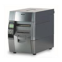
Tally Dascom 7010R Maintenance Manual (255 pages)
Brand:
Tally Dascom
| Category:
Printer
| Size: 8.77 MB
Table of Contents
English
6
Chapter 1 Specifications
5
Table of Contents
6
General Specifications
7
Printable Area
13
Printing Position Accuracy
14
Adjustable Sensors/Front Fixed Sensor
15
Operation of each Mechanism
20
Locations of Main Electrical Parts
20
Operation of Control Parts
32
Configuration of Printer
32
AC Inlet & Power Switch/Filter & Power Supply Section
33
Main PCB
33
Operation Panel
34
Sensors
34
Thermal Print Head
34
Connect PCB
35
Ethernet I/F (Option)
35
Motors
35
Parallel I/F (IEEE1284)
35
Serial I/F (RS-232C)
35
USB (Universal Serial Bus) I/F
35
Wireless LAN I/F (Option)
35
Memory Map
36
Sensors
37
Top Cover Open Sensor
37
Head up Sensor
38
Adjustable Sensor
39
Front Fixed Sensor
41
Head Temperature Sensor
42
PF Motor Temperature Sensor
43
Ribbon Encoder
44
Rewinder Cover Open Sensor (7010R Only)
45
Rewinder Motor Temperature Sensor (7010R Only)
46
Peel Sensor (7010R Only)
47
Drivers
48
PF Motor Driver
48
Head Driver
49
Rewinder Motor Driver (7010R Only)
51
Operation Panel
53
External View
53
Keys
53
LCD (Liquid Crystal Display)
53
Leds
53
Menu Setup Mode
54
Self Print Mode
54
Test Mode
54
Hex Dump Mode
55
Menu List Print Mode
56
Factory/Service Mode
57
How to Enter Factory/Service Mode
57
How to Print the Factory Mode Settings Menus
59
How to Change the Settings in Factory Mode
62
Submenu Table in Factory Mode
62
Setting Submenu in Factory Mode
65
How to Operate Submenus in Service Mode
66
Submenu Table in Service Mode
66
Submenu Operation in Service Mode
67
Interface
69
Serial Interface
69
Signal Line and Pin Assignment
69
Specifications
69
Protocol
70
Parallel Interface
71
Signal Line and Pin Assignment
71
Specifications
71
Compatible Timing Specification
72
Parallel Port Status Signals When an Error Occurs
72
Signal Line and Pin Arrangement
74
Specifications
74
USB Interface
74
Maintenance Precautions
78
Cleaning
79
Lubrication/Adhesive Agent
79
Adhesive Agen
79
Lubrication
79
Maintenance Tools List
80
Disassembly, Reassembly and Lubrication
81
Unit, Head
83
Unit, Roller Platen
84
SA, Ope-Pane PCB and SA, Cover Open Sens
85
Unit, Power Supply
86
Disconnecting All Connectors from the SA, Main PCB
88
SA, Main PCB and Unit, Centro PCB
88
Removing SA, Main PCB and Unit, Centro PCB
89
SA, Fan
90
SA1, Top Cover
90
Unit, Mechanism
91
Each Unit on the Unit, Mechanism
93
Disassembling the SA, Base Guide Open
95
Removing the SA, Base Guide Open
95
SA, Base Guide Open
95
Removing the Unit, Sensor Adjust
96
Unit, Sensor Adjust
96
Disassembling the Unit, Sensor Adjust
97
Unit, Frame Ribbon L
99
Disassembling the SA, Frame Ribbon R
102
Disassembling the SA, Front Tension Arm
102
Disassembling the Unit, Frame Rear
102
Disassembling the Unit, Frame U
103
Disassembling the Unit, Frame
104
Disassembling the Rewinder Part (7010R Only)
106
Separating the Rewinder Part
107
Removing the Rewinder Mechanism Block
109
Removing the Rewinder Door and SA1, Peeler
110
Removing the SA, Peeler Sensor/Friction Roller/Idle Rewinder Roller
111
Removing the SA, Rewinder Motor
112
Removing the SA, Interlock SW
113
Damper Roller (3 Pcs.) of the Rewinder Cover Block
114
Damper Roller (4 Pcs.) of the Rewinder Mechanism Block
114
Measure Sensor Rollers (4 Pcs.)
114
Peel Roll on the Printer Part
114
Removing Rollers
114
Removing SA, Rewinder PCB
114
Notes on Assembling the Springs
115
Adjustments
116
Sensor Position Adjustment (Factory Mode)
116
Sensor Sensitivity Adjustment (Factory Mode)
116
Transparent/Reflective Sensor Position Adjustment
116
Init Fix-Thru Sensitivity Adjustment
117
Init Fix-Refl Sensitivity Adjustment
119
Init Adj-Thru Sensitivity Adjustment
121
Init Adj-Refl Sensitivity Adjustment
123
Belt Tension Adjustment
125
Ribbon Skew Adjustment
126
Ribbon Tension Adjustment
127
Error Message and Corrective Actions
135
Troubleshooting
137
Chapter 2 Operating Principles
20
7010/7010-300/7010 (Printer Part)
20
7010 (Rewinder Part)
22
Media Feed Mechanism
23
Label/Tag Position Detection Mechanism
24
Top Cover Open Detection Mechanism
26
Print Head Up/Down Detection Mechanism
27
Head Balance Adjustment Mechanism
28
Media Thickness Adjustment Mechanism
29
Rewinder Cover Open Detection Mechanism (7010R Only)
30
Rewinding Mechanism (7010R Only)
31
Chapter 3 Disassembly and Maintenance
78
Chapter 4 Troubleshooting
137
Problems in Powering up the Printer
137
Media-Feed Problems
138
Problems in Printing
139
Ribbon-Feed Problem
140
Sensor Problems
141
Operation Panel Problems
145
Rewinder Problems (7010R Only)
146
Rewinding Problem (7010R Only)
146
Rewinder Sensor Problem (7010R Only)
147
Connector Location
148
Recommended Spare Parts List
152
Drawing No. 1
154
Chapter 5 Parts Lists
154
Parts List & Location for General Assembly
154
Drawing No. 2
159
Parts List & Location for Unit, Mechanism
159
Drawing No. 3
163
Parts List & Location for Unit, Frame U
163
Drawing No. 4
167
Parts List & Location for SA, Front Tension Arm
167
Drawing No. 5
170
Parts List & Location for Unit, Frame Rear
170
Drawing No. 6
173
Parts List & Location for SA, Frame Ribbon R
173
Drawing no
176
Parts List & Location for SA, Base Guide Open
176
Drawing No. 8
179
Parts List & Location for Unit, Sensor Adjust
179
Drawing No. 9
183
Parts List & Location for Unit, Frame
183
Drawing No. 10
187
Parts List & Location for Unit, Top Cover
187
Drawing No. 11
190
Parts List & Location for SA, Ope-Pane
190
Drawing No. 12
193
Parts List & Location for SA, Front Center
193
Drawing No. 13
196
Parts List & Location for SA, Front Right
196
Drawing No. 14
199
Parts List & Location for Unit, PCB
199
Recommended Spare Parts List
205
Drawing No. 1
207
Parts List & Location for General Assembly
207
Drawing no
212
Parts List & Location for Unit, Rewinder
212
Drawing no
218
Parts List & Location for SA1, Peeler
218
Drawing No. 4
221
Parts List & Location for SA2, Peeler
221
Circuit Diagrams
225
Chapter 6 Circuit Diagrams
226
Inter Connection (Main PCB 1/15) (7010/7010-300)
226
Inter Connection (Main PCB 1/15) (7010R)
227
Circuit Diagram (Main PCB 2/15) [CPU (1)]
228
Circuit Diagram (Main PCB 3/15) [CPU (2)/DAC]
229
Circuit Diagram (Main PCB 4/15) [ROM]
230
Circuit Diagram (Main PCB 5/15) [RAM]
231
Circuit Diagram (Main PCB 6/15) [Custom IC]
232
Circuit Diagram (Main PCB 7/15) [Head Control]
233
Circuit Diagram (Main PCB 8/15) [PF Motor Control]
234
Circuit Diagram (Main PCB 9/15) [Sensor]
235
Circuit Diagram (Main PCB 10/15) [Power/Buzzer/Fan]
236
Circuit Diagram (Main PCB 11/15) [Rfid/Ope-Pane]
237
Circuit Diagram (Main PCB 12/15) [Cutter/Rewinder]
238
Circuit Diagram (Main PCB 13/15) [Centronics I/F]
239
Circuit Diagram (Main PCB 14/15) [Serial I/F]
240
Circuit Diagram (Main PCB 15/15) [USB I/F]
241
Circuit Diagram (Power Supply PCB (100/240V))
242
Circuit Diagram (Ope-Pane PCB)
243
Circuit Diagram (Centronics PCB)
244
Circuit Diagram (Connect PCB) (7010/7010-300)
245
Circuit Diagram (Rewinder PCB) (7010R)
246
External Size Diagram
249
Mounting Diagrams
250
Main PCB
250
Power Supply PCB (100V/220V
251
Centro PCB
253
Ope-Pane PCB
253
Connect PCB (7010/7010-300
254
Rewinder PCB (7010R
254
Advertisement
Advertisement
Related Products
Tally Dascom 7008
Tally Dascom 7006
Tally Dascom 7106Series
Tally Dascom 7206 Series
Tally Dascom 7210 Series
Tally Dascom 7010
Tally Dascom 7010-300
Tally Dascom 7106
Tally Dascom 1125+
Tally Dascom 1140
Tally Dascom Categories
Printer
Label Maker
Barcode Reader
Network Card
Computer Hardware
More Tally Dascom Manuals
Login
Sign In
OR
Sign in with Facebook
Sign in with Google
Upload manual
Upload from disk
Upload from URL