Sign In
Upload
Manuals
Brands
Skoda Manuals
Automobile
Octavia II 2004
Skoda Octavia II 2004 Manuals
Manuals and User Guides for Skoda Octavia II 2004. We have
11
Skoda Octavia II 2004 manuals available for free PDF download: Workshop Manual, Maintenance Manual
Skoda Octavia II 2004 Workshop Manual (203 pages)
Brand:
Skoda
| Category:
Automobile
| Size: 4.26 MB
Table of Contents
Table of Contents
3
Starter, Current Supply, CCS
9
Contact Corrosion
9
Battery
10
Basics
10
Warning Instructions and Safety Precautions When Working on the Battery
10
Work Sequence When Disconnecting and Connecting the Battery
10
Checking Battery
13
Charging Battery
13
Removing and Installing Battery
13
Removing and Installing the Battery Tray in the Engine Compartment
14
Battery Parameterisation
15
Battery Types
16
Battery with a Magic Eye
16
Fleece Battery (AGM Battery)
16
Removing and Installing Starter
17
Starter
17
Alternator
19
Checking Generator
19
Removing and Installing Alternator
19
Fixing the B+ Wire to the AC Generator
21
Checking the Carbon Brushes of the AC Generator
21
Removing and Installing the Bosch Voltage Regulator
22
Removing and Installing the Valeo Voltage Regulator
22
Removing and Installing V-Ribbed Belt Pulley on Alternator
23
Removing and Installing the V-Ribbed Belt Pulley with Free Wheel
23
Removing and Installing the Cruise Control (CC)
24
Start-Stop" System
25
Safety Precautions for Vehicles with "Start-Stop" System
25
General Description
25
Protected by Copyright. Copying for Private or Commercial Purposes, in Part or in Whole, Is Not Permitted
26
Fault Recognition and Fault Display
26
Replacing the Battery on Vehicles with "Start-Stop" System
26
Battery Recharging or Starting by External Source on Vehicles with "Start-Stop System
26
Voltage Stabiliser J532
27
With Respect to the Correctness of Information in this Document. Copyright by ŠKODA AUTO A. S
27
Battery Monitor Control Unit J367
27
Button for "Start-Stop" System
28
Gauges, Instruments
29
Dash Panel Insert
29
Adjust/Replace Dash Panel Insert
30
Removing and Installing the Dash Panel Insert
30
Relacing Shield with Transparent Washer
32
Warning Light Symbols in Dash Panel Insert - Vehicles up to MY 08
33
Warning Light Symbols in Dash Panel Insert - Vehicles as of MY 09
34
Service Interval Display
35
The Self-Diagnostic Function of the Dash Panel Insert
37
Radio, Telephone, Navigation
38
Radio
38
General Instructions
38
Electronic Anti-Theft Coding
38
Overview of Radio System
39
Plug Connections on the Radio
40
Removing and Installing a Radio
41
Self-Diagnostic Function of Radio System
47
Aerial Systems
48
Overview of the Aerial Systems
48
Removing and Installing Aerial Module R108
49
Roof Aerial for Radio
50
Roof Aerial for Operating the Radio and Mobile Phone
51
Roof Aerial for Radio, Telephone and Navigation System - Vehicles as of MY 09
52
Roof Aerial for Radio, Telephone and Navigation System - Vehicles up to MY 08
52
Navigation System
55
General Description
55
General Instructions
56
Electronic Anti-Theft Coding
56
Overall View of the Navigation System
57
Plug Connections on the Navigation System
58
Removing and Installing the Navigation System
60
Self-Diagnosis of the Navigation System
61
Telephone System
62
General Instructions
62
Basic Mobile Phone Pre-Installation
63
Universal Mobile Phone Pre-Installation with Voice Control GSM Ll
63
Summary of Components, Removing and Installing the Mount for the Mobile Phone
64
Universal Mobile Phone Pre-Installation with Voice Control GSM Lll
64
Removing and Installing the Control Unit for the Mobile Phone Operating Electronics J412 (Vehicles up to CW 44/08)
66
Removing and Installing the Control Unit for the Mobile Phone Operating Electronics J412 (Vehicles as of CW 45/08)
67
Removing and Installing the Microphone for the Telephone R38
68
Multi-Functional Steering Wheel
69
Multifunctional Steering Wheel- Vehicles up to MY 08
69
Multifunctional Steering Wheel- Vehicles as of MY
71
Self-Diagnosis of the Multi-Functional Steering Wheel
73
Sound System
74
General Description
74
General Instructions
74
Overall View of the Equipment Soundsystem
74
Removing and Installing Amplifier R12 (up to MY 08)
76
Removing and Installing Amplifier R12 (up to MY 08)", Page
76
Removing and Installing Amplifier R12 (Vehicles as of MY 09)
76
Contact Assignment at the Amplifier - Vehicles up to MY
78
Contact Assignment at the Amplifier - Vehicles up to MY 08
78
Contact Assignment at the Amplifier - Vehicles as of MY
80
Contact Assignment at the Amplifier - Vehicles as of MY 09
80
Self-Diagnosis of the Equipment Soundsystem
81
Loudspeaker System
82
Removing and Installing Loudspeakers
82
CD Changer
85
Removing and Installing CD Changer
85
Contact Assignment on the CD Changer
86
Connection for External Audio Sources R199 (AUX)
87
Removing and Installing Connection for External Audio Sources R199 (AUX)
87
Connection for External Audio Sources MEDIA-IN (Multimedia Socket)
88
Removing and Installing Connector Socket for External Audio Sources (Multimedia Socket)
88
Removing and Installing Multimedia Socket Control Unit
88
Remove and Install Reservoir, Pumps and Sensor for Washer Fluid Level
90
Windscreen Wash/Wipe System
90
Windscreen Washer System
90
Removing and Installing the Spray Nozzles for Windscreen Washer System
91
Adjusting Spray Jet
92
Removing and Installing Rear Window Spray Nozzle Octavia
92
Removing and Installing Rear Window Spray Nozzle Octavia Combi
92
Repairing Washer Fluid Lines
92
Windscreen Wiper and Washer System
93
Removing and Installing Rear Window Wiper
97
Removing and Installing Sensor for Rain and Light Detection G397
100
Headlamp Cleaning System
102
Removing and Installing Headlight Cleaning System Pump V11
102
Removing and Installing the Lift Cylinder for Spray Nozzles of Headlights - Vehicles up to MY
102
Removing and Installing Spray Nozzle Holder - Vehicles as of MY 09
103
Bleed the Headlamp Cleaning System
104
Removing and Installing the Lift Cylinder for Spray Nozzles of Headlights - Vehicles as of MY
104
Headlights - Halogen Headlights
105
Lights, Bulbs, Switches - Exterior
105
Summary of Components Headlights - Vehicles up to MY 08 and Octavia Tour
105
Summary of Components of Headlights - Vehicles as of MY 09 (Except Octavia Tour)
106
Removing and Installing Headlight
107
Setting the Headlight Beam
107
Replacing Light Bulbs in the Headlight - Vehicles up to MY 08 and Octavia Tour
108
Replacing Light Bulbs in the Headlight - Vehicles as of MY 09 (Except Octavia Tour)
110
Change Headlight for Right-Hand / Left-Hand Traffic
112
Fault Recognition and Fault Display
116
Headlights with Xenon Discharge Lamps
116
Headlight with Xenon Discharge Lamps- Vehicles up to MY 08
117
Headlights with Xenon Discharge Lamps and Cornering Light - Vehicles as of My 09
121
General Description
121
Summary of Components of Headlight
122
Replacing Bulb for Main Beam H1
123
Replacing Xenon Discharge Lamp D1S
123
Replacing Bulb for Turn Signal Light PY21W
124
Remove and Install Performance Module for the Headlight J668 Right or J667 Left
125
Removing and Installing Control Unit for Gas Discharge Lamp J344 Right or J343 Left
125
Removing and Installing Control Unit for Headlight Range Control J431 or Cornering Light and Headlight Range Control Unit J745
126
Removing and Installing Vehicle Level Sensor G78 Front Left or G76 Rear Left
126
Contact Assignment of Plug Connection for Control Unit for Headlight Range Control J431 or Cornering Light and Headlight Range Control Unit J745
127
Removing and Installing Side Turn Signal Lights - Vehicles as of MY 09
128
Removing and Installing Side Turn Signal Lights - Vehicles up to MY 08
128
Side Turn Signal Lights
128
Octavia
130
Tail Lights
130
Octavia Combi
131
Fog Lights, Fog Lights with the "Corner" Function and Daylight Driving Light
133
General Description, Fault Recognition and Fault Display
133
Removing and Installing Fog Light/Daylight Driving Light
134
Lamps for Daylight Driving Light - Octavia Scout (Vehicles as of CW 22.10)
136
Replacing the Lamp for the Fog Light and for the Fog Light with the "Corner" Function
136
Replacing the Lamp for the Fog Light and for the Fog Light with the Corner Function
136
Removing and Installing Light Bulb for Daylight Driving Light (Except Octavia RS and Scout) - Vehicles as of MY
137
Vehicles as of MY 09
137
Adjusting Fog Lights, Fog Lights with the "Corner" Function
138
Adjusting Fog Lights, Fog Lights with the Corner Function
138
Daylight Driving Light and Parking Light Octavia "RS" - as of CW 22/09
138
Daylight Driving Light and Parking Light Octavia RS - as of CW
138
Additional Brake Light
139
Removing and Installing the High Level Brake Light - Octavia
139
Removing and Installing the High Level Brake Light - Octavia Combi
139
Advertisement
Skoda Octavia II 2004 Workshop Manual (257 pages)
2.0/100; 103 kW TDI PD Engine
Brand:
Skoda
| Category:
Automobile
| Size: 6.66 MB
Table of Contents
Table of Contents
3
Technical Data
7
Engine Number
7
Engine Characteristics
7
Self-Diagnosis
8
Self Diagnosis, Safety Measures, Cleanliness Regulations and Directions
8
Additional Instructions When Undertaking Assembly Work on the Air-Conditioning System
8
Safety Precautions When Working on Fuel Supply System
9
Safety Precautions When Working on the Diesel Direct Injection System
9
Regulations Concerning Cleanliness When Working on the Fuel Supply/Fuel Injection System
10
Regulations Concerning Cleanliness When Working on the Exhaust Gas Turbocharger
10
General Instructions for Charge Air System
11
Removing and Installing Engine
13
Removing Engine
13
Securing the Engine to the Assembly Stand
20
Installing Engine
21
Unit Mounting - Tightening Torques
25
Checking and Adjusting the Assembly Bracket
26
Crankshaft Group
29
Disassembling and Assembling Engine
29
Removing and Installing V-Ribbed Belt
29
Removing and Installing Toothed Belt for Engines with Code BKD, AZV
32
Removing and Installing Toothed Belt for Engines with Code BMM
44
Removing and Installing Sealing Flange and Flywheel
54
Replace Crankshaft Seal on Belt Pulley Side
55
Removing and Installing the Sealing Flange on the Belt Pulley Side
57
Replace Sealing Flange on the Gearbox Side
59
Removing and Installing the Two-Mass Flywheel
65
Crankshaft, Piston and Conrod
67
Removing and Installing Crankshaft
67
Removing and Installing Drive Chain Sprocket
68
Replace Needle Bearing for Crankshaft
68
Disassembling and Assembling Pistons and Conrods
69
Inspect Piston Projection at TDC
73
Separating New Connecting Rod
74
Cylinder Head, Valve Gear
75
Removing and Installing Cylinder Head
75
Summary of Components for Engines with Code BKD, AZV
75
Removing and Installing Cylinder Head Cover for Engines with Code BKD, AZV
78
Removing and Installing Cylinder Head for Engines with Code BKD, AZV
79
Checking the Compression Pressure for Engines with Code BKD, AZV
87
Summary of Components for Engines with Code BMM
87
Removing and Installing Cylinder Head Cover for Engines with Code BMM
89
Removing and Installing Cylinder Head for Engines with Code BMM
91
Checking the Compression Pressure for Engines with Code BMM
99
Repairing Valve Gear
101
Summary of Components for Engines with Code BKD, AZV
101
Checking the Axial Play of the Camshafts for Engines with Code BKD, AZV
103
Replacing the Sealing Rings for Camshafts for Engines with Code BKD, AZV
103
Removing and Installing Camshafts for Engines with Code BKD, AZV
104
Removing and Installing Valve Levers for Engines with Code BKD, AZV
111
Checking the Hydraulic Supporting Elements for Engines with Code BKD, AZV
113
Replacing Valve Stem Seals for Engines with Code BKD, AZV
114
Valve Dimensions for Engines with Code BKD, AZV
116
Summary of Components for Engines with Code BMM
117
Checking the Axial Play of the Camshaft for Engines with Code BMM
118
Replacing the Sealing Ring for Camshaft for Engines with Code BMM
119
Removing and Installing the Camshaft for Engines with Code BMM
121
Checking the Hydraulic Bucket Tappets for Engines with Code BMM
124
Replacing Valve Stem Seals for Engines with Code BMM
125
Valve Dimensions for Engines with Code BMM
127
Inspecting Valve Guides
127
Lubrication
128
Removing and Installing Parts of the Lubrication System
128
Disassembling and Assembling the Oil Filter Holder
130
Removing and Installing Oil Pan
131
Removing and Installing Oil Pump
133
Testing Oil Pressure and Oil Pressure Switch
133
Cooling
135
Removing and Installing Parts of the Cooling System
135
Parts of the Cooling System Fitted to Body for Engines with Code BKD, AZV
135
Parts of the Cooling System Engine Side for Engines with Code BKD, AZV
137
Connection Diagram for Coolant Hoses for Engines with Code BKD, AZV
139
Draining and Topping up Coolant for Engines with Code BKD, AZV
141
Removing and Installing
143
Removing and Installing Radiators for Engines with Code BKD, AZV
144
Parts of the Cooling System Fitted to Body for Engines with Code BMM
145
Parts of the Cooling System Engine Side for Engines with Code BMM
147
Connection Diagram for Coolant Hoses for Engines with Code BUD
149
Draining and Topping up Coolant for Engines with Code BMM
149
Fan Shroud for Radiator Fans V7 and V35 for Engines with Code BMM Removing and Installing
151
Removing and Installing the Radiator for Engines with Code BMM
152
Removing and Installing Coolant Pump
153
Removing and Installing Coolant Regulator
153
Check Cooling System for Leaks
154
Fuel Supply System
156
Removing and Installing Parts of the Fuel Supply System
156
Fuel Tank with Attached Parts for Vehicles with Front-Wheel Drive
156
Fuel Tank with Attached Parts for Vehicles with Four-Wheel Drive
158
Removing and Installing Fuel Filter
160
Extract Fuel from the Fuel Tank
161
Removing and Installing Fuel Cooler
163
Remove and Install the Fuel Tank for Vehicles with Front-Wheel Drive
163
Removing and Installing Fuel Tank for Vehicles with Four-Wheel Drive
165
Removing and Installing the Fuel Delivery Unit on Vehicles with Front-Wheel Drive
167
Removing and Installing the Fuel Delivery Unit on Vehicles with Four-Wheel Drive
168
Removing and Installing the Fuel Gauge Sender G
173
Removing and Installing Fuel Gauge Sender G169 on Vehicles with Four-Wheel Drive
175
Removing and Installing the Suction Jet Pump for Vehicles with Four-Wheel Drive
176
Removing and Installing Tandem Pump, Vehicles with Engine Code BKD, AZV
177
Removing and Installing Tandem Pump, Vehicles with Engine Code BMM
178
Inspecting a Tandem Pump
180
Inspecting Fuel Pump
185
Accelerator Control
188
Assembly Overview - Accelerator Module
188
Removing and Installing Accelerator Pedal Module
188
Turbocharging/Supercharging
190
Charge-Air System with Exhaust Gas Turbocharger - Part 1
190
Connection Diagram for Vacuum Hoses for Engines with Code BKD, AZV
190
Connection Diagram for Valve Block and Vacuum Sockets for Engines with Code BKD, AZV
191
Checking the Vacuum Actuator and Tension Rods for Charge Pressure Regulation for Engines with Code BKD, AZV
191
Skoda Octavia II 2004 Workshop Manual (211 pages)
Brand:
Skoda
| Category:
Air Conditioner
| Size: 4.31 MB
Table of Contents
Service
3
Table of Contents
3
Technical Data
5
General Notes on the Air Conditioning System
5
Important Instructions
5
Further Documentation and Information Means
6
Principles of the Air-Conditioning Technology
6
Advantages of the Air Conditioning System - Comfort
8
Operation of the Air Conditioning System
8
Refrigerant R134A
9
Vapour Pressure Table for Refrigerant R134A
10
Properties of Refrigerant R134A
11
Evidence of Leaks
12
Refrigerant Oil
13
General Occupational Safety
13
Using Pressure Tank
15
Safety Precautions When Working with Extraction and Filling Systems
16
Safety Measures When Working on Vehicles with Air Conditioning System and When Using
17
Basics for Working on the Refrigerant Circuit
18
General Instructions for Refrigerant Circuit
21
Extractor, Filler and Measurement Valves for Quick Couplings of the AC Service Station on the
26
Pressures and Temperatures in the Refrigerant Circuit and Its Arrangement
28
Switch and Sender on the Refrigerant Circuit
32
Electrical Components Which Are Not Fitted on the Refrigerant Circuit
33
The Inspection and Measurement Work Can be Performed Using the Pressure Gauge
34
Air Conditioning Service and Recycling Equipment
35
Repair and Maintenance Instructions for Refrigerant Circuit
35
Legal Texts and Legal Regulations
37
Laws and Regulations
37
Verification Procedure of Refrigerant
38
Refrigerant Circuit
39
Important Repair Instructions for Air Conditioning Systems
39
Working with the A/C Service Station
40
Important Instructions for Working with the A/C Service Station
41
Connecting the A/C Service Station to the Refrigerant Circuit for Measuring and Testing
42
Empty the Refrigerant Circuit with the A/C Service Station
42
Important Instructions for Working with the A/C Service Station
42
Evacuate the Refrigerant Circuit with the A/C Service Sta- Tion
43
Evacuate the Refrigerant Circuit with the A/C Service Station
43
Fill Refrigerant into the Reservoir (Filling Cylinder or Reservoir Bottle) of the A/C Service Station
44
Fill the Refrigerant Circuit with the A/C Service Station
44
Operate the Air Conditioning System after Filling
44
Draining the A/C Service Station
45
Leak Detection on the Refrigerant Circuit
46
Looking for Leaks in the Refrigerant Circuit - Important Instructions
46
Leak Detection on the Refrigerant Circuit with Compressed Air or Nitrogen
47
Detecting Leaks on the Refrigerant Circuit with the Leak Detector VAG1796
49
Detecting Leaks on the Refrigerant Circuit with the Leak Detector VAS 6196 or VAS 6201A
49
Cleaning the Refrigerant Circuit with Compressed Air and Nitrogen
56
Removing Contaminants from the Refrigerant Circuit
56
Cleaning Refrigerant Circuit with Refrigerant R134A (Flush)
58
Principle Circuit Diagrams for Different Rinsing Cycles
62
Adapter for Setting up the Rinsing Cycles
65
Complaints
70
Possible Complaints
70
Temperature Test of Cooling Capacity
71
Odour from the Heating and Air Conditioning Unit
72
Check the Pressure in the Refrigerant Circuit (with the A/C Service Station)
75
Test Requirements before the Pressure Test
75
Check Pressures
76
Continuation of the Test Depending on the Arrangement of the Refrigerant Circuit
78
Pressure Test for Vehicles with Throttle and Catch Pan (with AC Compressor Regulated from the Inside)
78
Pressure Test for Vehicles with Expansion Valve and Fluid Reservoir (with AC Compressor Regulated from the Inside)
82
Replace Components of the Refrigerant Circuit
95
Replace Parts on the Refrigerant Circuit - General Instructions
95
Components of the Refrigerant Circuit Leaking or Damaged - the Refrigerant Circuit Is Absolutely Empty
96
Components of the Refrigerant Circuit Leaking or Damaged - Refrigerant Is Still in the Refrigerant Circuit
97
Replace AC Compressor
97
Replace Catch Pan and Throttle/Fluid Reservoir
98
Tools and Materials, Which Are Avail- Able from the Importer
100
Tools and Materials, Which Are Available from the Importer
100
A/C Service Station
101
Flushing Device for the Refrigerant Circuits 6336/1 or Fol- Low-Up Models (Manufacturer Waeco)
102
Flushing Device for the Refrigerant Circuits 6336/1 or Follow-Up Models (Manufacturer Waeco)
102
Flushing Device for the Refrigerant Circuits 6337/1 or Fol- Low-Up Models (Manufacturer Behr)
102
Flushing Device for the Refrigerant Circuits 6337/1 or Follow-Up Models (Manufacturer Behr)
102
Leak Detection System VAS 6196
102
Leak Detector V.A.G 1796
102
Adapter Case of Motor Car Set VAS 6338/1
103
Case of Release Tools VAS 6127/3
103
Leak Detection System VAS 6201A
103
Socket Insert T10364
103
Setting up Tools and Materials Which Are Available from a Dealer
104
Tools and Materials, Which Are Commercially Available
104
Bottle Connecting Piece for Pressure Bottle
105
Filling Hoses
105
Valve Caps with Replacement Gaskets
105
A/C Service Station
106
Pressure Gauge with Pressure Reducer for Nitrogen
106
Quick-Coupling Adapter for Service Connections
106
Tools, Which You Make Yourself
106
Service
109
Heating
111
Summaries of Components, Disassembling and Assembling the Heater Unit
111
Summary of Components - Interior
111
Assembly Overview - Heater Unit
113
Disassembling and Assembling the Heater Unit
114
Summary of Components: Heat Exchanger, Heating Element for Air Auxiliary Heating Z35
116
Dash Panel Vent and Air Guide Ducts, Ventilation
117
Removing and Installing the Centre Dash Panel Vent
117
Remove and Install Footwell Vent
118
Removing and Installing the Right/Left Side Vent
118
Remove and Install the Forced Ventilation Frame for Passenger Compartment, Check
119
Heater Control
121
Removing and Installing Heater Control
121
Plug Connections at the Heater Control
122
Removing and Installing Flex Shafts
122
Advertisement
Skoda Octavia II 2004 Workshop Manual (209 pages)
Brand:
Skoda
| Category:
Automobile
| Size: 2.96 MB
Table of Contents
Table of Contents
3
Technical Data
7
Brakes
7
Brake Variants and Their Assignment
7
Brake Fluid
14
Brake Inspection
14
Anti-Lock Brake System
16
Antilock Braking System (ABS)
16
General Instructions for ABS
16
Distinguishing Features of the ABS Systems
19
Safety Precautions, Basic Information on Fault Finding and on Repairing
20
Required Technical Information
20
Electrical/Electronic Components and Fitting Locations ABS Mark 70 (ABS/TCS)
21
Up to MY 2008
21
As of MY 2009
23
As of MY 2011
25
Electrical/Electronic Components and Fitting Locations ABS Mark 60/Mark 60 EC (ABS/EDL/TCS/ESP (ESC))
27
Electrical/Electronic Components and Fitting Locations ABS Mark 60 for Vehicles up to MY 2008
27
Electrical/Electronic Components and Fitting Locations Mark 60 EC for Vehicles as of MY 2009
30
Electrical/Electronic Components and Fitting Locations ABS Mark 60 EC/PYA for Vehicles as
33
Of MY 2011
33
Indication of Faults by Means of Warning Lights
35
Warning Lights - for Vehicles up to MY 2008
35
Warning Lights - for Vehicles as of MY 2009
39
Warning Lights - for Vehicles as of MY 2011
43
Hydraulic Control Unit, Brake Servo Unit/Master Brake Cylinder ABS Mark 70 (ABS/TCS)
48
Summary of Components - Left-Hand Drive
48
Connect the Brake Lines from the Master Brake Cylinder to the Hydraulic Unit - Left-Hand Drive
51
Removing and Installing ABS Control Unit J104 ABS Hydraulic Unit N55 - Left -Hand Drive Vehicles
51
Disconnecting Control Unit from Hydraulic Unit - Left-Hand Drive
57
Connecting the Brake Lines from the Master Brake Cylinder to the Hydraulic Unit - Right-Hand Drive
60
Separating the Control Unit from the Hydraulic Unit - Right-Hand Drive
65
Attaching Control Unit to Hydraulic Unit - Right-Hand Drive
66
Hydraulic Control Unit, Brake Servo Unit/Master Brake Cylinder ABS Mark 60/Mark 60 EC (ABS/EDL/TCS/ESP (ESC))
67
Summary of Components ABS Mark 60 - for Left-Hand Drive up to MY 2008
67
Summary of Components ABS Mark 60 EC - for Left-Hand Drive as of MY 2009
70
Connecting the Brake Lines from the Master Brake Cylinder to the ABS Hydraulic Unit - Left
72
Hand Drive
72
Removing and Installing ABS Control Unit J104 ABS Hydraulic Unit N55 - Left -Hand Drive Vehicles
73
Disconnecting Control Unit from Hydraulic Unit - Left-Hand Drive
78
Attaching Control Unit to Hydraulic Unit - Left-Hand Drive
79
Summary of Components ABS Mark 60 EC (ABS/EDL/TCS/ESP) - Right-Hand Drive
79
Hand Drive
81
Removing and Installing ABS Control Unit J104 / ABS Hydraulic Unit N55 - Right-Hand Drive
82
Separating the Control Unit from the Hydraulic Unit - Right-Hand Drive
85
Attaching Control Unit to Hydraulic Unit - Right-Hand Drive
86
Removing and Installing Parts of the ABS System on the Front and Rear Axle
88
Removing and Installing Parts of the ABS System on the Front Axle
88
Removing and Installing Parts of the ABS System on the Rear Axle (Front-Wheel Drive)
91
Removing and Installing Parts of the ABS System on the Rear Axle (Four-Wheel Drive)
94
Removing and Installing Parts of the ESP (ESC) System
97
Removing and Installing Sensor Unit for ESP (ESC) G419
97
Removing and Installing Steering Angle Sender G85
99
Brakes - Mechanism
100
Repairing Front Wheel Brake
100
Changing the Brake Pads of the Front Brake - Mounting Instructions
100
Repairing Front Wheel Brake, Floating Caliper Disc Brake FS-Iil
101
Removing and Installing Brake Pads, Floating Caliper Disc Brake FS-III
102
Removing and Installing Brake Caliper, Floating Caliper Disc Brake FS-III
106
Repairing Front Wheel Brake, Brake Caliper FN3
109
Removing and Installing Brake Pads, Brake Calliper FN3
110
Removing and Installing Brake Caliper, Brake Caliper FN3
114
Repairing Rear Brake
117
Changing the Brake Pads of the Rear Brake - Mounting Instructions
117
Repairing Rear Brake CII 41 (Vehicles with Front and Four-Wheel Drive)
118
Removing and Installing Brake Pads CII 41
120
Removing and Installing Brake Caliper CII 41
123
Repairing Rear Brake CI 38 (Vehicles with Front-Wheel Drive)
125
Removing and Installing Brake Pads CI 38
126
Removing and Installing Brake Caliper CI 38
129
Repairing Rear Brake Bosch BIRIII (Vehicles with Front and Four-Wheel Drive)
131
Removing and Installing Brake Pads Bosch BIRIII
132
Removing and Installing Brake Caliper Bosch BIRIII
136
Handbrake
138
Handbrake Lever - Summary of Components
138
Setting the Hand-Brake
138
Removing and Installing the Hand-Brake Cable
139
Brake Pedal - Left-Hand Drive
141
Summary of Components of Brake Pedal
141
Separating the Brake Pedal from the Brake Servo Unit and Clipping Onto Brake Servo Unit
143
Removing and Installing Brake Pedal
143
Removing and Installing Bearing Bracket
144
Setting, Removing and Installing the Brake Light Switch F and Brake Pedal Switch F47 up to MY 10.2005
144
Removing and Installing Brake Light Switch F and Brake Pedal Switch F47 as of 11/2005
145
Brake Pedal - Right-Hand Drive
149
Summary of Components of Brake Pedal
149
Skoda Octavia II 2004 Maintenance Manual (202 pages)
Brand:
Skoda
| Category:
Automobile
| Size: 3.41 MB
Table of Contents
Table of Contents
3
General Points
5
Vehicle Identification Data
5
Type Plate
8
Vehicle Data Sticker
8
Check Identification of Vehicle Window Glazing
9
Storage of ŠKODA New Vehicles
9
Vehicle Handover from Stock
9
Additional Customer Information Regarding Inspection and Maintenance
9
Determine the Age of the Vehicle
11
Inspections
12
Pre-Delivery Inspection -PDI- (Export)
12
Pre-Sales Inspection - Domestic (Czech Republic)
14
Delivery Inspection (Export)
18
Service Intervals
21
Oil Change Service
27
Countries with High Sulphur Content in the Diesel Fuel
29
Dust-Rich Countries
29
Service Tables
30
Service Tables with Variations for the Individual Markets
36
Engines
44
Engine Overview
44
Engine Fitted
50
With Respect to the Correctness of Information in this Document. Copyright by ŠKODA AUTO A. S.� Replacing the Timing Belt or also the Tensioning Roller
54
Inspecting Timing Belt for Camshaft Drive for Wear and Running
55
Inspecting Engine Oil Level
55
Draining or Suctioning off Engine Oil and Filling up with Engine Oil
56
Replace Engine Oil Filter
63
Inspecting Antifreeze Protection, Replenishing Coolant Additive if Necessary
67
Inspecting Coolant Level (Volume)
71
V-Ribbed Belt: Check Condition
72
Routing of V-Ribbed Belt
72
Replace Spark Plugs
75
Replace Air Filter Element
75
Replacing the Fuel Filter (Diesel Engine)
76
Checking Diesel Particle Filter
83
Liquefied Petroleum Gas System (LPG)
86
Sticker LPG Vehicle
86
Safety Measures and Rules of Cleanliness When Working on Vehicles with Liquefied Petroleum Gas System (LPG)
88
Check LPG Gas System for Leaks
90
Querying the Event Memory of the LPG Control Unit
96
Erasing the Fault Memory of the Liquefied Petroleum Gas Control Unit (LPG)
99
Maintenance Scopes on the Gas System
100
Empty Gas System
100
Activate Gas System
102
Fuel Filter of the LPG System (Liquefied Petroleum Gas): Change
103
3.17.10 Paper Filter on the Evaporator: Change
105
Gas Hoses: Visual Inspection for Damage
107
Check Evaporator for Oil Pollution or Other Soilings
108
Cover and LPG Filler Neck: Check Condition, Clean if Necessary and Check O-Rings
109
Multiple-Purpose Additive for Petrol Engines
110
3.17.14 Sealing LPG Reservoir
110
3.17.15 Removing LPG Reservoir
110
Replace Fuel Filter - Petrol Engines
111
Gearbox
112
6-Speed Gearbox DSG: Change Gear Oil, Replace Oil Filter
117
Changing the Oil in the Four-Wheel Drive Clutch
122
Chassis
125
Inspecting Thickness of Front and Rear Brake Pads/Linings
125
Inspecting Brake System for Leaks and Damage
126
Change Brake Fluid
127
Inspecting the Brake Fluid Level
134
Track Rod Ends: Check Play, Fastening and Sealing Flanges
135
Inspecting Tyres (Including Spare Wheel)
135
Inspecting Tyre Tread Depth (Including Spare Wheel) and Entering
136
Tightening Wheel Bolts to Specific Torque
137
Inspecting the Tyre Pressure (Including Spare Wheel), if Necessary Correcting Pressure
137
Tyre Inspection Display: Basic Setting
158
Transport Lock: Remove Anti-Lock Components from the Springs of the Front Axle
159
Breakdown Set
160
Electrical System
161
Power Windows: Check Positioning
161
Electric Consumers: Check They Are Functioning
162
Checking Battery
162
Inspecting Proper Operation of Radio and Navigation System
162
Inspecting Proper Operation of Radio and Navigation Sys- Tem
162
Setting Clock
163
Connect Diagnostic Unit
164
Skoda Octavia II 2004 Workshop Manual (198 pages)
Brand:
Skoda
| Category:
Automobile
| Size: 5.72 MB
Table of Contents
Service
2
Table of Contents
3
Technical Data
5
Identification of the Gearbox
5
Location on the Gearbox
5
Identification Characters, Aggregate Assignment, Ratios
6
Identification Characters, Aggregate Assignment, Ratios (Octavia II)
10
Identification Characters, Aggregate Assignment, Ratios (Fabia II)
10
Identification Characters, Aggregate Assignment, Ratios (Roomster)
11
Identification Characters, Aggregate Assignment, Ratios (Rapid India)
12
Identification Characters, Aggregate Assignment, Ratios (Rapid)
12
Identification Characters, Aggregate Assignment, Ratios (Superb II)
13
Identification Characters, Aggregate Assignment, Ratios (Octavia III)
13
Torque Con- ⇒ Electronic Catalogue of Original Parts
13
Gear
13
Reverse Gear
13
Intermediate Drive Wheel
13
Gear Output Gear
13
Ratio
13
Final Drive Output Shaft
13
Crown Wheel
13
Contents
14
Information for the Automatic Gearbox 09G
16
Torque Converter
16
Atf
16
Information and Repair Instructions for the Automatic Gearbox 09G
16
Repair Instructions
17
Explanation of the Terms Used in this Workshop Manual
19
Draining the Torque Converter
21
Removing and Installing Gasket Ring for Torque Converter
21
Checking the Torque Converter
22
Installing the Torque Converter
22
Controls, Housing
24
Electric and Electronic Components, Fitting Locations of the Automatic Gearbox
24
Summary of Components
24
Summary of Components - Electric and Electronic Components, Fitting Locations of the Automatic Gearbox
30
Removing and Installing Automatic Gearbox Control Unit J217
42
Install
43
Removing
43
Removing and Installing Automatic Gearbox Control Unit
43
Assembly Overview - Shift Mechanism
45
Repairing Shift Mechanism
45
Summary of Components - Gearshift Mechanism -Octavia II up to 10.2009
45
Summary of Components - Gearshift Mechanism - Octavia II as of 11.2009
48
Summary of Components - Gearshift Mechanism -Superb II
50
Summary of Components - Shift Mechanism up to 10.2011
51
Summary of Components - Shift Mechanism as of 11.2011
53
Gearshift Mechanism
55
Inspecting the Gearshift Mechanism
58
Inspecting and Adjusting the Selector Lever Control Cable
59
Check the Function of the Ignition Key Removal Lock
61
Removing and Installing the Cover for the Shift Mechanism
62
Removing and Installing and Installing Selector Lever Handle up to 10.2012
69
Removing and Installing Retractor Spring
70
Removing and Installing Selector Lever Handle
73
Removing and Installing Selector Lever Handle as of 11.2012
74
Installing the Lock Button at the Selector Lever Handle
76
Removing and Installing Selector Mechanism
78
Removing and Installing Slave Cylinder
84
Remove and Install Shift Mechanism
88
Removing and Installing Shift Mechanism
92
Removing and Installing the Selector Lever Control Cable
96
Removing and Installing Selector Lever Lock Solenoid N110
104
Removing and Installing the Tiptronic Switch F189
104
Checking the Plug Connections at the Gearshift Mechanism
108
Emergency Release of Gearshift Mechanism out of Position "P
109
Removing and Installing the Gearbox
111
Removing the Gearbox
111
Removing Gearbox
115
Installing the Gearbox
136
Tightening Torques
138
M10
142
M12
142
Screws 1) -1
142
Screws/Nuts M6
142
Nm + Torque a Further Mounting, Screws / 4 Turn)
143
Screws / 4 Turn)
143
Attaching Gearbox to Assembly Stand
149
Transporting an Automatic Gearbox
149
Check the ATF Level Level and Top up
151
Change ATF or Top up after Repair
156
ATF Coolant Circuit
159
ATF Radiator - Summary of Components
159
Summary of Components for Gearboxes with KGV, KGU
160
Removing and Installing ATF Radiator
163
Skoda Octavia II 2004 Workshop Manual (182 pages)
Brand:
Skoda
| Category:
Automobile
| Size: 8.3 MB
Table of Contents
Table of Contents
3
Technical Data
5
Identification of the Gearbox
5
Identification Characters, Aggregate Assignment, Ratios, Filling Capacities (Octavia II)
6
Identification Characters, Aggregate Assignment, Ratios, Filling Capacities (Octavia III)
8
Overview of Transmission System
9
Designation of Components and Transmission Ratio
9
Safety Instructions
10
Safety Measures for Working on Vehicles with Start/Stop System
10
Electrical Components
11
Summary of Components: Electrical Components
11
General Repair Information
12
Clutch
16
Repairing Clutch Control
16
Summary (Octavia II)
17
Overview of the Fitting Positions: Clutch Control (Octavia III)
18
Summary of Components - Foot Controls (Octavia Ll)
19
Summary of Components: Foot Controls (Octavia III)
20
Removing and Installing Bearing Bush (Octavia III)
22
Removing and Installing Retractor Spring (Octavia II)
22
Removing and Installing Retractor Spring (Octavia III)
24
Removing and Installing Over-Centre Helper Spring (Octavia III)
26
Removing and Installing Clutch Pedal (Octavia II)
28
Removing and Installing Clutch Pedal (Octavia Ili)
30
Removing and Installing Bearing Bracket (Octavia II)
32
Removing and Installing Bearing Bracket for Clutch Pedal (Octavia III)
34
Removing and Installing Master Cylinder (Octavia II)
38
Removing and Installing Master Cylinder (Octavia Iil)
39
Removing and Installing Clutch Position Sender G476 (Octavia II)
40
Removing and Installing Clutch Position Sender G476 (Octavia Iil)
42
Summary of Components - Hydraulic System (Octavia Ll)
42
Summary of Components: Clutch Hydraulics (Octavia III)
45
Checking the Hydraulic Clutch Control (Octavia II)
47
Checking the Master and Slave Cylinder (Octavia III)
48
Removing and Installing Slave Cylinder (Octavia II)
48
Removing and Installing Master Cylinder (Octavia III)
50
Removing and Installing Cables for Clutch Control (Octavia III)
51
Bleeding the Clutch Control (Octavia II)
53
Bleeding the Clutch Control (Octavia III)
54
Repairing Clutch Control
56
Repairing the Clutch Control (Octavia II)
56
Summary of Components: Clutch Control (Octavia III)
58
Repairing the Clutch Control (Octavia III)
58
Repairing Clutch
60
Repairing the Clutch (Octavia II)
60
Summary of Components: Clutch (Octavia III)
62
Removing and Installing Clutch (Octavia Ili)
63
Fault Finding Power Transmission - Problems with the Clutch and Clutch Control (Octavia II)
66
Controls, Housing
72
Shift Mechanism
72
Fitting Location of Shift Mechanism
72
Summary of Components Shift Mechanism (Octavia Ll)
74
Summary of Components - Gearshift Knob with Shift Lever Collar (Octavia II)
75
Summary of Components: Gear Shift Knob and Shift Lever Collar (Octavia III)
76
Removing and Installing Gearshift Knob and Shift Lever Collar (Octavia II)
77
Removing and Installing Gear Shift Knob (Octavia Ili)
77
Summary of Components - Shift Mechanism up to 10.2006 (Octavia II)
78
Summary of Components - Shift Mechanism as of 11.2006 (Octavia II)
81
Disassembling and Assembling Shift Mechanism as of 11.2006 (Octavia II)
82
Summary of Components - Control Cables up to 10.2006 (Octavia II)
86
Summary of Components - Control Cables as of 11.2006 (Octavia II)
89
Plastic Relay Lever (Octavia II)
91
Summary of Components: Gearshift Mechanism (Octavia III)
93
Removing and Installing Shift Mechanism (Octavia II)
98
Removing and Installing Shift Mechanism and Selector Cable (Octavia II)
101
Remove and Install Shift Mechanism (Octavia Ili)
104
Setting Shift Mechanism (Octavia II)
106
Setting Shift Mechanism (Octavia Ili)
108
Removing and Installing the Gearbox
111
Removing Gearbox (Octavia II)
111
Removing Gearbox (Octavia III)
117
Transporting the Gearbox
123
Install Gearbox (Octavia II)
123
Installing Gearbox (Octavia III)
125
Check Gear Oil Level
131
Disassembling and Assembling the Gearbox
132
Gearbox - Summary of Components
132
Summary of Components
133
Removing and Installing Gearbox Housing Cover and 5Th Gear
134
Detaching and Attaching Clutch Housing
135
Removing and Installing the Drive Shaft, Output Shaft, Differential Gear, Shift Mechanism and Gearshift Forks
136
Mounting Sequence
137
Repairing Gearbox Housing and Clutch Housing
145
Repairing Shift Mechanism
149
Replacing the Gasket Ring for the Gearshift Shaft
150
Disassembling and Assembling the Gearshift Forks
152
Skoda Octavia II 2004 Workshop Manual (194 pages)
Brand:
Skoda
| Category:
Automobile
| Size: 5.16 MB
Table of Contents
Table of Contents
3
Technical Data
5
Identification
5
Identification of the Gearbox
5
Safety Instructions
6
Safety Precautions When Working on Vehicles with a Start/Stop System
6
Safety Precautions During Road Tests in Which Testing and Measuring Equipment Is Used
6
Safety Measures for Working on the Mechatronics for Double Clutch Gearbox J743
6
General Points
8
Repair Instructions
8
Explanation of the Terms Used in this Workshop Manual
11
Contact Corrosion
13
Gaskets and Seals
13
Nuts and Bolts
13
Working with Testing Devices
14
Notes on Tow Starting and Towing
15
Technical Data
16
Filling Capacity
16
Allocation Gearbox - Engine
17
Calculation of Gear Ratios
25
Overview of Transmission System
26
Electrical Components
27
Electric/Electronic Components and Fitting Locations of the Automatic Gearbox DSG - 0AM
27
Clutch
36
Clutch Operation
36
Assembly Overview - Clutch Release Mechanism
36
Removing and Installing Clutch Release Mechanism
38
Adjust Clutch Release Mechanism
45
Summary of Components - Double Clutch
67
Clutch
67
Remove Double Clutch
70
Install Double Clutch
73
Replacing the Sealing Ring for the Outer Drive Shaft
78
Replace Gasket Ring for Inner Drive Shaft
79
Controls, Housing
81
Mechatronics for Double Clutch Gearbox J743
81
Summary of Components - Mechatronics for Double Clutch Gearbox J743
81
Remove Mechatronics for Double Clutch Gearbox J743 ; Gearbox Installed
83
Bringing the Mechatronics for Double Clutch Gearbox J743 to the Removal Position by Hand
91
Install Mechatronics for Double Clutch Gearbox J743 ; Gearbox Installed
93
Shift Mechanism
101
Summary of Components - Gearshift Mechanism
101
Summary of Components - Gearshift Mechanism
107
Inspecting the Gearshift Mechanism
108
Inspecting and Adjusting the Selector Lever Control Cable
109
Inspecting the Gearshift Mechanism
109
Check the Function of the Ignition Key Removal Lock
112
Removing and Installing the Cover for the Shift Mechanism
113
Removing and Installing Handle for Shift Mechanism
116
Removing and Installing Handle for Shift Mechanism", Page
116
Removing and Installing the Cover for the Shift Mechanism
116
Installing the Lock Button at the Selector Lever Handle
120
Removing and Installing Shift Mechanism with Selector Lev
122
Removing and Installing Shift Mechanism with Selector Lever Control Cable
122
Removing and Installing Selector Lever Control Cable, Vehicles up to 05.2009
127
Removing and Installing Selector Lever Control Cable, Vehicles up to 05.2009 (Octavia II, Superb II, Yeti)
127
Superb II, Yeti)
127
Emergency Release of Gearshift Mechanism out of Posi- Tion P
131
Emergency Release of Gearshift Mechanism out of Position P
131
Removing and Installing Selector Lever Lock Solenoid N110
134
Removing and Installing Selector Lever Switch Locked in P F319
134
Removing and Installing the Selector Lever Sensor Control Unit J587
134
Removing and Installing the Tiptronic Switch F189
134
Checking the Plug Connections at the Shift Mechanism (Octavia II, Superb II, Yeti)
135
Removing and Installing the Gearbox
136
Removing the Gearbox
136
Installing the Gearbox
169
Tightening Torques
173
Transport the Gearbox and Secure to the Assembly Support
176
Change Gearbox Oil
178
Gears, Shafts
181
Pinions and Shafts
181
Final Drive - Differential
182
Replace Gasket Rings for Rigid Shafts and Flange Shafts
182
Summary of Components - Gasket Rings and Output Shafts
182
Replacing Gasket Ring for Left Rigid Shaft (Octavia II, Superb II, Yeti)
183
Replacing Gasket Ring for Right Rigid Shaft (Octavia II, Superb II, Yeti)
186
Replacing the Left Flange Shaft Gasket Ring
189
Replacing the Right Flange Shaft Seal Ring
192
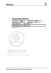
Skoda Octavia II 2004 Workshop Manual (144 pages)
Propshaft and rear final drive
Brand:
Skoda
| Category:
Automobile
| Size: 2.45 MB
Table of Contents
Table of Contents
3
Technical Data
5
Safety Instructions
5
Safety Precautions for Working on Vehicles with Start-Stop System
5
Safety Precautions During Road Tests in Which Testing and Measuring Equipment Is Used
5
Safety Measures During Towing/Tow-Starting
5
General Safety Instructions
5
Identification
7
Identification of Rear Final Drive
7
Repair Instructions
9
Rules of Cleanliness
9
General Repair Instructions
9
Seals and Sealing Rings
10
Screws, Nuts
10
Technical Data
12
Allocation Gearbox - Engine
12
Filling Capacity
14
Electrical Components
15
Fitting Location Summary - Electrical Components
15
Final Drive - Rear Differential
20
Propshaft
20
Summary of Components - Propeller Shaft
20
Removing and Installing Propshaft from Rear Final Drive
25
Removing and Installing Propshaft
30
Repairing Propshaft
47
Removing and Installing the Front Flexible Disk
49
Removing and Installing the Rear Flexible Disk
50
⇒ "1.1.1 Summary of Components - Propshaft, Octavia II up to
54
05/2007
54
Summary of Components - Propshaft, Octavia II as of 06/2007
58
Summary of Components - Propshaft, Superb
62
Summary of Components - Propshaft, Yeti
66
Final Drive
67
Summary of Components - Final Drive
67
Removing and Installing the Rear Final Drive
69
Assembly Carrier
82
Summary of Components - Assembly Carrier
82
Removing and Installing Rubber-Metal Bearing
83
Sealing Rings
87
Replacing Left Sealing Ring
87
Replacing Right Sealing Ring
88
Replacing Gasket Ring for Output Flange of the Rear Final Drive
89
Axle Oil in Final Drive
94
Installation Location Overview - Drain Plug and Check Screw
94
Check the Oil Level in the Final Drive
94
Four-Wheel Drive Clutch
96
Summary of Components - Four-Wheel Drive Clutch
96
Summary of Components - Four-Wheel Drive Clutch Control Unit
106
Functional Test of Four-Wheel Drive Clutch
109
Checking Oil Level in the Four-Wheel Drive Clutch
110
Skoda Octavia II 2004 Workshop Manual (117 pages)
Brand:
Skoda
| Category:
Automobile
| Size: 2.99 MB
Table of Contents
Table of Contents
3
Starter, Current Supply, CCS
5
Battery
5
Basics about Batteries
5
Battery Types
5
Warning Instructions and Safety Precautions When Working on the Battery
8
Working on the Airbag System
9
Screwed Connections of Battery Poles
10
Checking Battery
11
Check Battery with a Magic Eye
11
Checking Fleece Battery (AGM)
14
Visual Inspection of the Battery
14
Notes on Battery Replacement and Battery Degassing
15
Battery Tester with Printer VAS 6161
16
Battery Tester with Printer VAS 5097 a
21
Check Current Drain When Charging
22
Load Voltage Measurement - Demonstration Vehicles and Stock Vehicles
23
Charge Battery
24
Charging Battery
24
Severely Discharged Batteries
26
Cruise Control System (CCS)
28
General Description
28
Activate/Deactivate Cruise Control System
28
Windscreen Wash/Wipe System
29
Repairing Washer Fluid Level Pipes
29
Repair Solution for Plain Ended Pipe
29
Repair Solution for Corrugated Pipe
30
Washer Fluid Lines
34
Connections of Washer Fluid Level Pipes
34
Joint-Free Wiper Blades
36
Distinguishing Features of Joint-Free Wiper Blades
36
Lights, Bulbs, Switches - Exterior
37
Gas Discharge Lamps
37
Use and Safety Instructions for Gas Discharge Lamps
37
LED Headlights
39
Application and Safety Instructions for LED Headlights
39
Lights, Bulbs, Switches - Interior
40
Power Sockets, Cigarette Lighter
40
Removing and Installing the 12 V Power Socket/Cigarette Lighter in the Centre Console
40
Protected by Copyright. Copying for Private or Commercial Purposes, in Part or in Whole, Is Not Permitted
40
Wiring
43
Vehicle Diagnosis, Testing and Information Systems
43
Safety Instructions
43
Connect Vehicle Diagnosis, Measurement and Information System VAS 505X
43
Wiring Harness Repair
45
General Instructions for the Repair on the Vehicle Electrics
45
General Instructions for Wiring Harness and Plug Repair
46
Tool Descriptions
47
Repair of Airbag and Belt Tensioner Cables
52
Repair of CAN Bus Lines
54
Crimp New Contacts
55
Skoda Octavia II 2004 Workshop Manual (103 pages)
Brand:
Skoda
| Category:
Automobile
| Size: 2.79 MB
Table of Contents
Table of Contents
3
General Instructions
5
Technical Data
5
Vehicle Identification Data
5
Safety Measures
6
Safety Instructions
6
Straightening Bench Work
6
Disassembling Components
6
Battery
6
Paint, Windows, Upholstery, Trims
6
Welding Work
7
Air Conditioning
7
Fuel Tank and Fuel Conveying Hoses
8
Electronic Control Units
8
Airbag System
8
Safety Instructions for Seat Belt Tensioners
9
Basic Instructions
10
Accident Repair Sequence
10
Diagnosis of Vehicles Damaged by Accident
10
Condition of the Body or Parts When Delivered to the Paintshop
10
Straightening
10
Severance Cuts
11
Welding of Galvanized Body Panels
11
Repair of High-Strength Body Panels
12
Body - Glued Joints
13
Removing the Underbody Protection and Sealing Seams
14
Protected by Copyright. Copying for Private or Commercial Purposes, in Part or in Whole, Is Not Permitted
14
Body Sections and Individual Parts
14
With Respect to the Correctness of Information in this Document. Copyright by ŠKODA AUTO A. S
14
Original Welding
14
Explanation of the Symbols
15
Explanation of the Signs for Welding Operations
15
Explanation of the Signs for the Processes
16
Tools
18
Anti-Corrosion Measures
19
Corrosion Prevention
19
Long-Term Body Protection
19
Cutting Galvanized Body Parts
20
Injecting Foam in the Body
21
Replace Noise Insulation
21
Overview of Foam-Filled Points
21
The Jig Alignment Bench
23
Overview of the Jig Alignment Bench Celette with Straightening Square Set
23
Overview of Front Alignment Bracket Positions
26
Overview of the Middle Alignment Bracket Positions
32
Overview of the Rear Alignment Bracket Positions
34
Karosserie-Kontrollspaltmaße
36
Karosserie Vorn
36
Karosserie Hinten
37
Front Body
38
Repairing the Front Body
38
Replacing Wing Support
38
Replace Engine Mounting
39
Replace Gearbox Mount
40
Replacing Upper Frame Side Rail
41
Replacing the Front Frame Side Rail
45
Replacing the Front Frame Side Rail Offcut Part
48
Advertisement
Related Products
Skoda Fabia II 2007
Skoda Fabia II 2009
Skoda Superb II 2008
Skoda Octavia II 2005
Skoda Octavia II 2006
Skoda Superb II 2012
Skoda Superb II 2014
Skoda Superb II 2017
Skoda Superb II 2016
Skoda Superb II 2015
Skoda Categories
Automobile
Car Receiver
Automobile Accessories
Car Navigation system
Car Video System
More Skoda Manuals
Login
Sign In
OR
Sign in with Facebook
Sign in with Google
Upload manual
Upload from disk
Upload from URL