Sign In
Upload
Manuals
Brands
Rexroth Indramat Manuals
Controller
DURADRIVE SYSTEM200
Rexroth Indramat DURADRIVE SYSTEM200 Manuals
Manuals and User Guides for Rexroth Indramat DURADRIVE SYSTEM200. We have
2
Rexroth Indramat DURADRIVE SYSTEM200 manuals available for free PDF download: Project Planning Manual
Rexroth Indramat DURADRIVE SYSTEM200 Project Planning Manual (180 pages)
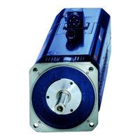
Drive Controllers with degree of protection IP 65
Brand:
Rexroth Indramat
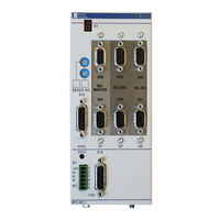
| Category:
Controller
| Size: 4.11 MB
Table of Contents
Table of Contents
3
Introduction to the System
7
DURADRIVE Drive Controller
7
An Overview of Individual Components of the DURADRIVE Family
9
An Overview of the Drive Controllers
10
Type Code for Drive Controller HDC
10
Type Code for Cooling Fan Unit
10
An Overview of the Communications Interfaces
11
An Overview of Measuring Systems Supported
12
Overview of the Motors
13
MKD Synchronous Motor for Standard Applications
13
MHD Synchronous Motors for High-Precision Applications
14
MKE Synchronous Motor for Potentially Explosive Areas
15
2AD Asynchronous Motor for Standard Applications
15
ADF Asynchronous Motor for Standard Applications
16
1MB Asynchronous Assembly Motor
16
MBW Asynchronous Motor for Printing Roller Applications
17
MBS Synchronous Assembly Motor
17
LSF Linear Synchronous Assembly Motor
18
Important Directions for Use
19
Appropriate Use
19
Introduction
19
Areas of Use and Application
20
Inappropriate Use
20
Safety Instructions for Electric Servo Drives
21
Introduction
21
Explanations
21
Hazards by Inappropriate Use
22
General Information
23
Protection against Contact with Electrical Parts
24
Protection by Protective Low Voltage (PELV) against Electrical Shock
26
Protection against Dangerous Movements
26
Protection against Magnetic and Electromagnetic Fields During Operations and Mounting
28
Protection against Contact with Hot Parts
29
Protection During Handling and Installation
29
Battery Safety
30
Protection against Pressurized Systems
30
DURADRIVE HDC01.1 Drive Controller
31
Technical Data
31
Dimensions
31
Ambient and Operating Conditions
33
Electric Data of the Individual HDC01.1 Components
36
Storable Energy in the Bus
44
Allowed DC Bus Peak Power
46
Allowed DC Bus Continuous Power
46
Sizing Components Relevant to Regeneration
48
CE Label, C-UL Listing, Tests
50
Electrical Connections - Independent of the Drive Controller Type
51
A Look at the Drive Controller and Connector Designations
51
Independent of the Drive Controller Type - Total Connecting Diagram
55
X1, Connections for Control Voltage
56
X2, Serial Interface
58
X3, Digital and Analog I/Os
62
X4, Encoder 1
68
X5, Motor Connections, Motor Temperature Monitoring and Holding Brake
71
X7, Connection for Programming Module
77
X8, Encoder 2
79
X10, Ecoxexpansion Interface
85
X11, Ready to Operate Contact Bb, Activation Power on
86
X13, Mains Connection
91
X14, Ventilator Connection
91
XE1, Protective Conductor Connections for Mains
93
XS1, XS2, XS3, XS4 Shield Connections
94
Electrical Connections - Dependent on the Drive Controller Type
95
HDC01.1-***N-SE01-01-FW - SERCOS Interface
95
HDC01.1-***N-PB01-01-FW - Profibus-DP Interface
99
HDC01.1-***N-IB01-01-FW - Interbus Interface
104
HDC01.1-***N-CN01-01-FW - Canopen Interface
107
HDC01.1-***N-DN01-01-FW - Devicenet Interface
109
HDC01.1-***N-SE02-01-FW - SERCOS Interface 2
111
DC24V NTM Power Supplies
113
Application Recommendations
113
Technical Data
113
Dimensional Sheets and Installation Dimensions
114
Front Views
114
Electrical Connection
115
Type Code
116
DST Transformers
117
Selection
117
Autotransformers for Drive Controllers
117
Type Code
120
Mains Connections
121
General
121
Grounding Conditions of the Power Supply Network
121
Earth-Leakage Circuit Breaker
122
Control Circuits for the Mains Connection
122
Control Circuits with E-Stop
123
Fuses
125
Computing Phase Current on the Mains
125
Computing Charging Current Inrush
125
Factor F for Computing the Connected Load
126
Selecting Fusing Q1
127
Constructing the Control Cabinet
129
Power Dissipation
129
General Notes
135
Wire Routing in the Cable Duct
136
State of Delivery of the Drive Components
137
Packaging
137
Papers
138
Extent of Delivery
138
Ordering
139
Replacement Parts
139
Additional Accessories
139
Mounting Accessories
139
Commissioning Aids
139
Identifying the Components
141
Component Designations
141
Type Plates
142
Replacing or Exchanging Drive Components
145
General
145
Procedure on Replacing the Unit
147
Replacing the Drive Controller
147
Replacing the Cooling Fan Unit
148
Replacing the Motor
150
Replacing Cables
150
Replacing Firmware
153
Replacing the Parameter Module
153
Replacing the Firmware Module
154
Replacing the Programming Module (Complete Module)
154
Attachment
155
Wire Routing and Wiring of the Drive Controller
155
RS485 Connector
156
What Is Needed to Prepare to Start-Up
157
Signal Sequence HDC01.1
158
Recommended Switching on Sequence
158
Recommended off Sequence
160
Cleaning the Drive Controller
162
Directory of Standards and Guidelines
163
Index
167
Service & Support
173
Helpdesk
173
Service-Hotline
173
Internet
173
Vor der Kontaktaufnahme
173
Kundenbetreuungsstellen - Sales & Service Facilities
174
Advertisement
Rexroth Indramat DURADRIVE SYSTEM200 Project Planning Manual (86 pages)
Brand:
Rexroth Indramat
| Category:
Industrial Electrical
| Size: 1.99 MB
Table of Contents
English
3
Table of Contents
3
1 Reco Plc Isp200-R
7
Front View MTS-R01.2 and MTS-R02.2
7
Brief Description of the ISP200-R
8
2 Important Directions for Use
9
Appropriate Use
9
Introduction
9
Areas of Use and Application
10
Inappropriate Use
10
3 Safety Instructions for Electric Drives and Controls
11
Introduction
11
Explanations
11
Hazards by Improper Use
12
General Information
13
Protection against Contact with Electrical Parts
14
Protection against Electric Shock by Protective Low Voltage (PELV)
15
Protection against Dangerous Movements
15
Protection against Magnetic and Electromagnetic Fields During Operation and Mounting
17
Protection against Contact with Hot Parts
18
Protection During Handling and Mounting
18
Battery Safety
19
Protection against Pressurized Systems
19
4 Technical Data
21
General Features
21
Supply Voltage
21
I/O Bus Supply by the Control
21
Derating of the I/O Bus Supply
21
Emc
22
Interfaces
22
Dimensions
23
MTS-R01.2 and MTS-R02.2
23
Installation Sizes of the RMB02.2-02 Module Carrier
24
5 Communication
27
Parameterization of the PROG Interface
27
Parameterization of the COM Interface
28
BT Bus
28
6 Startup
31
Slot Addressing of the Module Carriers
31
Installation Instructions
32
Installation of Module Carriers
32
Arrangement of Module Carriers
32
Connection of Supply Voltage and Watchdog
35
Recobus in the PLC Memory
36
Recobus Diagnosis
37
Status Information and Error Diagnosis
40
Indication of Operating States
40
Indication of Errors
40
Battery
41
Interface Assignment
41
7 Reco Plc Mts-R01.2
43
Brief Description
43
Application Example
44
Type Code
45
8 Reco Plc Mts-R02.2
47
Brief Description
47
Application Example
48
Type Code
49
9 INTERBUS Master Connection
51
Brief Description
51
Setting of the I/O Address
52
Technical Data
52
Fig. 9-3: Technical Data
52
Interface Assignment
53
Fig. 9-4: Pin Assignment of the INTERBUS Diagnosis Interface X64
53
Fig. 9-5: Pin Assignment of the INTERBUS Interface X60 (Remote Bus)
53
10 PROFIBUS DP Connection
55
Brief Description of Master and Slave Connection
55
Fig. 10-1: PROFIBUS Connections
55
Setting the I/O Addresses
56
Fig. 10-2: Setting of the Module Type
56
Status and Diagnosis Information
57
Technical Data
57
Interface Assignment
58
Fig. 10-3: Pin Assignment of the Diagnosis Interface RS232C (X74, X79)
58
Fig. 10-4: Pin Assignment of the PROFIBUS Interface (X70, X75)
58
11 Devicenet Master Connection
59
Brief Description
59
Setting of the I/O Address
60
Fig. 11-2: Maximum Cable Lengths Dependent on the Used Cable
60
Fig. 11-3: Setting of the I/O Address
60
Status and Diagnostic Displays
61
Technical Data
61
Interface Assignment
62
Fig. 11-4: Pin Assignment of the Devicenet Diagnostic Interface X84
62
Fig. 11-5: Pin Assignment of the Devicenet Interface X80
62
12 Serial Interfaces
63
Brief Description
63
Fig. 12-1: P.C.B. SIO 04-B
63
Address and Interrupt Settings
64
Function Blocks
64
Fig. 12-2: Jumper Settings on the P.C.B. SIO 04-B
64
Fig. 12-3: Function Blocks for Interface Handling
64
Technical Data
65
Interface Assignment
65
Fig. 12-4: Pin Assignment of RS 232C X35, X36
65
Fig. 12-5: Pin Assignment of RS422/485 X40, X41
65
13 Networking
67
Networking Via the PROG and COM Interfaces
67
Fig. 13-1: RS485 Connection with INS0619 Connector
67
Fig. 13-2: RS422 Connection with INS0645 Connector
67
ISP200-R in Connection with the BTV20/30
68
Fig. 13-3: ISP200-R Networking with BTV20/30
68
14 Connection of Operator Terminals
69
Applications with the BTV04/05/06
69
Fig. 14-1: MTS-R with Compact Operator Terminals Via an RS422 Interface
69
Fig. 14-2: MTS-R with Compact Operator Terminals Via an RS485 Interface
70
Applications with the BTC06
71
Fig. 14-3: MTS-R with BTC06 Via an RS232 Interface
71
Fig. 14-4: MTS-R with Via an RS422 Interface
72
15 Accessories
73
Selection List of Connectors and Ready-Made Cables
73
Fig. 15-1: MTS-R Accessories
75
Labeling of I/O Modules
76
Fig. 15-2: Labeling Accessories
76
Deutsch
77
Fig. 1-1: MTS-R01.2 and MTS-R02.2
7
Fig. 3-1: Hazard Classification (According to ANSI Z535)
11
Fig. 4-2: RMB02.2-02 Module Carrier
24
Fig. 4-3: Connection of One RMB02.2-02 and Several RMB02.2-04
24
Installation Sizes of the RMB02.2-04 Module Carrier
25
Fig. 5-1: DIP Switch for Parameterization of the PROG Interface
27
Fig. 5-2: Setting of the PROG Interface for the MTS-R01.2 and the MTS-R02.2
27
Fig. 5-3: BT Bus Overview
28
Addressing
29
Fig. 5-4: Storage Requirements of Operating Devices
29
Fig. 5-5: Storage Assignment of BT Bus
29
Fig. 6-1: Setting of Slot Addressing
31
Fig. 6-2: Maximum Number of RMB02.2-04 Carriers Fitted
32
Installation of Modules
33
Fig. 6-3: Maximum Number of RMB02.2-02 and RMB02.2-04 Carriers Fitted
33
Fig. 6-4: Fitting Variants for RMB02.2-02
33
Grounding
34
Fig. 6-5: System Grounding in Connection with the ISP200-R
34
Fig. 6-6: Connection of the Supply Connector X1
35
Fig. 6-7: Recobus I/O Modules in the Memory of the PLC
36
Fig. 6-8: Division of Diagnosis Double Word / Status Information
37
Fig. 6-9: Explanation of Status Bit 31
37
Error Detection by the User
38
Fig. 6-10: Error Detection
38
Fig. 6-11: Explanation of the Diagnosis Bit
38
External Voltage Monitoring
39
Example of an External Power Failure
39
Fig. 6-12: Voltage Monitoring
39
Fig. 6-13: Bit Explanation
39
Fig. 6-14: Example of an External Power Failure
39
Fig. 6-15: Operating States of the ISP200-R
40
Fig. 6-16: Error Codes of the ISP200-R
40
Fig. 6-17: Pin Assignment of the PROG Interface X10 and the COM Interface X16
41
Fig. 6-18: Pin Assignment of the BT Bus X15
41
Fig. 7-1: MTS-R01.2
43
Fig. 7-2: MTS-R01.2 with INTERBUS Connection
44
Fig. 7-3: MTS-R01.2 Type Code
45
Fig. 8-1: MTS-R02.2
47
Fig. 8-2: MTS-R02.2 with INTERBUS Connection and 4 Serial Interfaces
48
Fig. 8-3: MTS-R02.2 Type Code
49
Fig. 9-1: P.C.B. LK IBM 2
51
Fig. 9-2: Setting of DIP Switch S1
52
16 List of Figures
77
17 Service & Support
79
Helpdesk
79
Service-Hotline
79
Internet
79
Vor der Kontaktaufnahme
79
Kundenbetreuungsstellen - Sales & Service Facilities
80
Advertisement
Related Products
Rexroth Indramat BZM 01.3-01-07
Rexroth Indramat CLM1.4
Rexroth Indramat CZM 01.3-02-07
Rexroth Indramat DKC01.3-016-7
Rexroth Indramat DKC01.3-040-7
Rexroth Indramat DKC01.3-100-7
Rexroth Indramat DKC01.3-200-7
Rexroth Indramat DKC02.3-016-7
Rexroth Indramat DKC02.3-040-7
Rexroth Indramat DKC02.3-100-7
Rexroth Indramat Categories
Controller
Control Unit
Amplifier
Industrial Electrical
More Rexroth Indramat Manuals
Login
Sign In
OR
Sign in with Facebook
Sign in with Google
Upload manual
Upload from disk
Upload from URL