
Subscribe to Our Youtube Channel
Related Manuals for Rexroth Indramat DURADRIVE SYSTEM200


Summary of Contents for Rexroth Indramat DURADRIVE SYSTEM200
- Page 1 DURADRIVE Drive Controllers with degree of protection IP 65 Project Planning Manual SYSTEM200 DOK-DURADR-HDC01.1****-PR02-EN-P LSA Control S.L. www.lsa-control.com comercial@lsa-control.com (+34) 960 62 43 01...
- Page 2 1st edition DOK-DURADR-HDC01.1****-PR02-EN-P 07.01 edition 2001 Rexroth Indramat GmbH Copyright Copying this document, giving it to others and the use or communication of the contents thereof without express authority, are forbidden. Offenders are liable for the payment of damages. All rights are reserved in the event of the grant of a patent or the registration of a utility model or design (DIN 34-1).
-
Page 3: Table Of Contents
DURADRIVE Drive Controllers Contents Contents Introduction to the system DURADRIVE drive controller ......................1-1 An overview of individual components of the DURADRIVE family ..........1-3 An overview of the drive controllers ....................1-4 Type code for drive controller HDC ..................1-4 Type code for cooling fan unit.................... - Page 4 Contents DURADRIVE Drive Controllers DURADRIVE HDC01.1 Drive Controller Technical data..........................4-1 Dimensions ..........................4-1 Ambient and operating conditions ................... 4-3 Electric Data of the Individual HDC01.1 Components ............. 4-6 Storable energy in the bus ..................... 4-14 Allowed DC bus peak power....................4-16 Allowed DC bus continuous power ..................
- Page 5 DURADRIVE Drive Controllers Contents Mains Connections General............................7-1 Grounding conditions of the power supply network ............... 7-1 Earth-leakage circuit breaker ......................7-2 Control circuits for the mains connection ..................7-2 Control circuits with E-Stop...................... 7-3 Fuses.............................. 7-5 Computing phase current on the mains................... 7-5 Computing charging current inrush..................
- Page 6 Contents DURADRIVE Drive Controllers 12.2 What is needed to prepare to start-up ..................12-3 12.3 Signal sequence HDC01.1......................12-4 Recommended switching on sequence ................. 12-4 Recommended off sequence ....................12-6 12.4 Cleaning the drive controller ......................12-8 12.5 Directory of standards and guidelines..................12-9 13 Index 13-1 14 Service &...
-
Page 7: Introduction To The System
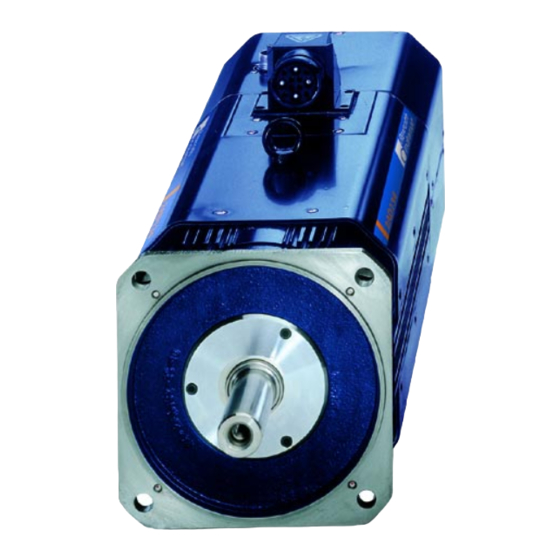
DURADRIVE Drive Controllers Introduction to the system Introduction to the system DURADRIVE drive controller PZ5015F1.FH7 Fig. 1-1: DURADRIVE drive controller The digital intelligent automation system DURADRIVE is the solution with a high degree of functionality for stand-alone drives under difficult ambient conditions. - Page 8 Introduction to the system DURADRIVE Drive Controllers Typical application areas are: • handling systems • packaging machines • assembly systems • printing machines • machine tools DOK-DURADR-HDC01.1****-PR02-EN-P LSA Control S.L. www.lsa-control.com comercial@lsa-control.com (+34) 960 62 43 01...
-
Page 9: An Overview Of Individual Components Of The Duradrive Family
DURADRIVE Drive Controllers Introduction to the system An overview of individual components of the DURADRIVE family System voltage Line filter for control voltage supply unit IKL - ready-made power cable Control voltage supply unit Drive controller DC 24 V Firmware IKS - ready-made feedback cable IKG - ready-made power cable AC motor... -
Page 10: An Overview Of The Drive Controllers
Introduction to the system DURADRIVE Drive Controllers An overview of the drive controllers Type code for drive controller HDC HDC 01.1 - A040N - PB01 - 01 - FW Example: Type code fields: Product group Line Design Cooling mode natural convection (heatsink outside) Rated current 40 A... -
Page 11: An Overview Of The Communications Interfaces
DURADRIVE Drive Controllers Introduction to the system An overview of the communications interfaces device type: CN01 DN01 IB01 PB01 PL02 SE01 SE02 interface RS232 / 485 CANopen interface DeviceNet interface InterBus interface Profibus-DP interface SERCOS interface SERCOS interface 2 Fig. 1-5: An overview of interfaces Note: Parallel interface 2 is only required in combination with the... -
Page 12: An Overview Of Measuring Systems Supported
Introduction to the system DURADRIVE Drive Controllers An overview of measuring systems supported Connecting the systems to the encoder inputs Encoder 1 (plug X4) Encoder 2 (plug X8) Type of Resolver with Resolver Sine encoder EnDat Gear-type Square-wave Digital motor without FDS encoder encoder with... -
Page 13: Overview Of The Motors
DURADRIVE Drive Controllers Introduction to the system Overview of the motors MKD synchronous motor for standard applications • general automation technology Application • handling systems • axes that only need to approach fixed positions (no path operation) • applications with low-precision demands (accuracy of up to approx. -
Page 14: Mhd Synchronous Motors For High-Precision Applications
Introduction to the system DURADRIVE Drive Controllers MHD synchronous motors for high-precision applications • Automated production with the highest demands for accuracy (up to Application 1/4000000 of a motor revolution) • high demands on dynamics • axes in path operation •... -
Page 15: Mke Synchronous Motor For Potentially Explosive Areas
DURADRIVE Drive Controllers Introduction to the system MKE synchronous motor for potentially explosive areas • potentially explosive areas such as: painting installations, chemical Application industries in general automation engineering • applications with low-precision demands (accuracy of up to approx. 1/20000 of one motor revolution) •... -
Page 16: Adf Asynchronous Motor For Standard Applications
1-10 Introduction to the system DURADRIVE Drive Controllers ADF asynchronous motor for standard applications • main spindle and servo axes in machine tools for drive tasks with high Application performance demands • highest demands on accuracy (up to 1/2000000 of a motor revolution possible) •... -
Page 17: Mbw Asynchronous Motor For Printing Roller Applications
1-11 DURADRIVE Drive Controllers Introduction to the system MBW asynchronous motor for printing roller applications • for printing roller applications with high demands for accuracy Application • motor for mounting directly onto the printing roller Construction • motor cooling method: liquid cooled Fig. -
Page 18: Lsf Linear Synchronous Assembly Motor
1-12 Introduction to the system DURADRIVE Drive Controllers LSF linear synchronous assembly motor • For precision applications in new compact machine concepts for main Application spindles and servo axes in lathes, milling machines, grinding machines and processing centers for use in high-speed processing •... -
Page 19: Important Directions For Use
The user alone carries all responsibility of the risks. Before using Rexroth Indramat products, make sure that all the pre- requisites for an appropriate use of the products are satisfied: • Personnel that in any way, shape or form uses our products must first read and understand the relevant safety instructions and be familiar with appropriate use. -
Page 20: Areas Of Use And Application
Important directions for use DURADRIVE Drive Controllers Areas of use and application Drive controllers made by Rexroth Indramat are designed to control electrical motors and monitor their operation. Control and monitoring of the motors may require additional sensors and actors. -
Page 21: Safety Instructions For Electric Servo Drives
If you do not have the user documentation for your equipment contact your local Rexroth Indramat representative to send this documentation immediately to the person or persons responsible for the safe operation of this equipment. -
Page 22: Hazards By Inappropriate Use
Safety Instructions for Electric Servo Drives DURADRIVE Drive Controllers Hazards by inappropriate use High voltage and high discharge current! Danger to life, risk of severe electrical shock and risk of injury! DANGER Dangerous movements! Danger to life and risk of injury or equipment damage by unintentional motor movements! DANGER High electrical voltage due to wrong... -
Page 23: General Information
DURADRIVE Drive Controllers Safety Instructions for Electric Servo Drives General Information • Rexroth Indramat GmbH is not liable for damages resulting from failure to observe the warnings given in these documentation. • Order operating, maintenance and safety instructions in your language before starting up the machine. -
Page 24: Protection Against Contact With Electrical Parts
Safety Instructions for Electric Servo Drives DURADRIVE Drive Controllers Protection against contact with electrical parts Note: This section refers to equipment with voltages above 50 Volts. Making contact with parts conducting voltages above 50 Volts could be dangerous to personnel and cause an electrical shock. When operating electrical equipment, it is unavoidable that some parts of the unit conduct dangerous voltages. - Page 25 DURADRIVE Drive Controllers Safety Instructions for Electric Servo Drives To be observed with electrical drives, power supplies, and filter components: High electrical voltage! High leakage current! Danger to life, danger of injury and bodily harm from electrical shock! ⇒ Before switching on power for electrical units, all DANGER housings and motors must be permanently grounded according to the connection diagram.
-
Page 26: Protection By Protective Low Voltage (Pelv) Against Electrical Shock
Safety Instructions for Electric Servo Drives DURADRIVE Drive Controllers Protection by protective low voltage (PELV) against electrical shock All connections and terminals with voltages between 5 and 50 Volts on INDRAMAT products are protective low voltages designed in accordance with the following standards on contact safety: •... - Page 27 DURADRIVE Drive Controllers Safety Instructions for Electric Servo Drives Dangerous movements! Danger to life and risk of injury or equipment damage! ⇒ Personnel protection must be secured for the above listed reason by means of superordinate monitors or DANGER measures. These are instituted in accordance with the specific situation of the facility and a danger and fault analysis conducted by the manufacturer of the...
-
Page 28: Protection Against Magnetic And Electromagnetic Fields During Operations And Mounting
Safety Instructions for Electric Servo Drives DURADRIVE Drive Controllers ⇒ Disconnect electrical power to the equipment using a master switch and secure the switch against reconnection for: - maintenance and repair work - cleaning of equipment - long periods of discontinued equipment use ⇒... -
Page 29: Protection Against Contact With Hot Parts
DURADRIVE Drive Controllers Safety Instructions for Electric Servo Drives Protection against contact with hot parts Housing surfaces could be extremely hot! Danger of injury! Danger of burns! ⇒ Do not touch surfaces near the source of heat! Danger of burns! CAUTION ⇒... -
Page 30: Battery Safety
3-10 Safety Instructions for Electric Servo Drives DURADRIVE Drive Controllers 3.11 Battery safety Batteries contain reactive chemicals in a solid housing. Inappropriate handling may result in injuries or equipment damage. Risk of injury through incorrect handling! ⇒ Do not attempt to reactivate discharged batteries by heating or other methods (danger of explosion and corrosion). -
Page 31: Duradrive Hdc01.1 Drive Controller
DURADRIVE Drive Controllers DURADRIVE HDC01.1 Drive Controller DURADRIVE HDC01.1 Drive Controller Technical data Dimensions Drive Controller HDC01.1-A040N 86.5 MB5056F1.FH7 Fig. 4-1: Drive Controller HDC01.1-A040N DOK-DURADR-HDC01.1****-PR02-EN-P LSA Control S.L. www.lsa-control.com comercial@lsa-control.com (+34) 960 62 43 01... - Page 32 DURADRIVE HDC01.1 Drive Controller DURADRIVE Drive Controllers Drive Controller HDC01.1-A040N ventilated 86.5 250.8 MB5063F1.FH7 Fig. 4-2: Drive Controller HDC01.1-A040N ventilated DOK-DURADR-HDC01.1****-PR02-EN-P LSA Control S.L. www.lsa-control.com comercial@lsa-control.com (+34) 960 62 43 01...
-
Page 33: Ambient And Operating Conditions
DURADRIVE Drive Controllers DURADRIVE HDC01.1 Drive Controller Drive Controller HDC01.1-A100N, HDC01.1-A200N 22.5 MB5064F1.FH7 Fig. 4-3: Drive Controller HDC01.1-A100/200N ventilated Ambient and operating conditions Selection lists are specified for each motor/drive combination. Ambient temperature and installation altitude The selection lists apply to motors and drives within the specified ambient and operating conditions (see "Fig. - Page 34 DURADRIVE HDC01.1 Drive Controller DURADRIVE Drive Controllers • of the motor: • output • continuous torque at standstill • S1 continuous torque • short-time operating torque M according to the diagrams (see "Fig. 4-4:Degree of utilisation as a value dependent on ambient temperature and installation altitude"). Load capacity dependent on installation elevation 1000...
- Page 35 DURADRIVE Drive Controllers DURADRIVE HDC01.1 Drive Controller Designation Symbol Unit HDC01.1-AXXXN Permissible ambient and air inlet °C +5 ... +45 temperature for the output ratings Storage and shipping temperatures °C -30 ... +85 Max. allowed installation altitude for 1000 the output ratings Max.
-
Page 36: Electric Data Of The Individual Hdc01.1 Components
DURADRIVE HDC01.1 Drive Controller DURADRIVE Drive Controllers Electric Data of the Individual HDC01.1 Components Mains connections, Power section HDC01.1-AXXXN 40 A 40 A 100 A 200 A Designation Symbol Unit ventilated ventilated ventilated ventilated Operating mode at the mains three phase Mains input voltage 3 x AC (200 ... - Page 37 DURADRIVE Drive Controllers DURADRIVE HDC01.1 Drive Controller 40 A 40 A 100 A 200 A Designation Symbol Unit ventilated ventilated ventilated ventilated Storable energy of the DC bus see diagram page 4-14: "Storable energy in the bus" capacitors nominal DC bus capacitance HDC 0,585 2,35 DC bus voltage...
- Page 38 DURADRIVE HDC01.1 Drive Controller DURADRIVE Drive Controllers Control voltage connection for HDC (Data applies to ambient temperature of 25°C) Designation Symbol Unit 40 A 40 A 100 A 200 A not ventilated ventilated ventilated ventilated Control voltage DC (21.6 ... 26.4) V max.
- Page 39 DURADRIVE Drive Controllers DURADRIVE HDC01.1 Drive Controller • Do not install connecting leads in parallel with mains leads and power cables, in order to avoid overvoltages caused by inductive or capacitive coupling. • Use shielded connecting leads. DOK-DURADR-HDC01.1****-PR02-EN-P LSA Control S.L. www.lsa-control.com comercial@lsa-control.com (+34) 960 62 43 01...
- Page 40 4-10 DURADRIVE HDC01.1 Drive Controller DURADRIVE Drive Controllers Amplitude of the HDC control voltage charging current at startup, to selecting power source charging current HDC040 not ventilated HDC040 ventilated HDC100 HDC200 t [ms] Current consumption after charging current inrush Fig. 4-9: Example of charging current inrush of control voltage Voltage connection for holding brake Designation Symbol...
- Page 41 4-11 DURADRIVE Drive Controllers DURADRIVE HDC01.1 Drive Controller Materials used, Mass Designation Symbol Unit 40 A 40 A 100 A 200 A not ventilated ventilated ventilated ventilated Mass materials used Free of asbestos and silicone Fig. 4-12: Materials used, Mass Output current characteristic curves for servo applications ( acceleration times <...
- Page 42 4-12 DURADRIVE HDC01.1 Drive Controller DURADRIVE Drive Controllers Output current characteristic curves for servo applications ( acceleration times ≥ 400 ms) The dynamic profile of the output current limit is illustrated using a temperture model without initial conditions, as a response to a sudden torque change at the motor.
- Page 43 4-13 DURADRIVE Drive Controllers DURADRIVE HDC01.1 Drive Controller 1 5 0 Io u t in A [4 k H z ] Io u t in A [8 k H z ] 1 0 0 1 0 0 2 0 0 3 0 0 4 0 0 5 0 0...
-
Page 44: Storable Energy In The Bus
4-14 DURADRIVE HDC01.1 Drive Controller DURADRIVE Drive Controllers Storable energy in the bus Note: The higher the connection voltage the lower the energy that can be stored in the DC bus as the differential voltage between bleeder threshold and DC bus voltage (threshold value of connecting voltage) decreases. - Page 45 4-15 DURADRIVE Drive Controllers DURADRIVE HDC01.1 Drive Controller HDC01.1-A100N mains input voltage UN1 in V Mains input voltage : Storable energy of the DC bus capacitors Fig. 4-18: Storable energy in the bus HDC01.1-A100N 1500 1400 1300 1200 1100 1000 mains input voltage UN1 in V Mains input voltage : Storable energy of the DC bus capacitors...
-
Page 46: Allowed Dc Bus Peak Power
4-16 DURADRIVE HDC01.1 Drive Controller DURADRIVE Drive Controllers Allowed DC bus peak power HDC01.1 Relationship peak to DC bus continuous power t in s Fig. 4-20: Allowed peak power in DC bus of HDC01.1-A040N HDC01.1-A040N are not suited for drive applications if the required intermittent operating power of the unit’s nominal power exceeds 50%! Allowed DC bus continuous power HDC040 not ventilated... - Page 47 4-17 DURADRIVE Drive Controllers DURADRIVE HDC01.1 Drive Controller 10,0 mains input voltage UN1 3*AC in V Fig. 4-22: Allowed DC bus continuous power of HDC01.1-A100N 2 5 ,0 2 0 ,0 1 5 ,0 1 0 ,0 5 ,0 0 ,0 1 5 0 2 0 0 2 5 0...
-
Page 48: Sizing Components Relevant To Regeneration
4-18 DURADRIVE HDC01.1 Drive Controller DURADRIVE Drive Controllers Sizing components relevant to regeneration With every application it has to be checked whether the stored • regeneration continuous power • regeneration peak power • regenerated energy can be absorbed by the internal bleeder (brake resistor). If the stored power and energy from the mechanical system exceed the capacity of the bleeder in the drive controller, the next larger unit can be used, if possible. - Page 49 4-19 DURADRIVE Drive Controllers DURADRIVE HDC01.1 Drive Controller Regenerative power 1. DC bus continuous power ≤ ZWD, η 2. DC bus peak power ≤ ZWS, (accelerat η 3. regeneration continuous power ≤ ⋅ π LAST ⋅ ⋅ ⋅ NUTZ ⋅ ⋅...
-
Page 50: Ce Label, C-Ul Listing, Tests
4-20 DURADRIVE HDC01.1 Drive Controller DURADRIVE Drive Controllers CE label, C-UL listing, Tests CE label CEf1.fh7 Fig. 4-25: CE label • Per UL508 C under file no. E134201. C-UL listing LISTED INDUSTRIAL CONTROL EQUIPMENT 97Y4 ULf2.fh7 Fig. 4-26: C-UL listing Tests High-voltage test according to Routine test with DC2100V... -
Page 51: Electrical Connections - Independent Of The Drive Controller Type
4-21 DURADRIVE Drive Controllers DURADRIVE HDC01.1 Drive Controller Electrical connections - independent of the drive controller type A look at the drive controller and connector designations Front view X14: ventilator connection XS4: shield connection X10: EcoX-expansion interface RS232/ RS485 device-typical interface programming module (firmware, Parameter) - Page 52 4-22 DURADRIVE HDC01.1 Drive Controller DURADRIVE Drive Controllers Connections on bottom of unit (HDC01.1-A040N) X13: crimped seal mains connection motor connection, holding brake, motor temperature monitoring FA5125F1.FH7 Fig. 4-29: Connections on bottom of unit for HDC01.1-A040N-xxxx-01-FW DOK-DURADR-HDC01.1****-PR02-EN-P LSA Control S.L. www.lsa-control.com comercial@lsa-control.com (+34) 960 62 43 01...
- Page 53 4-23 DURADRIVE Drive Controllers DURADRIVE HDC01.1 Drive Controller Connections on bottom of unit (HDC01.1-A100/200N) X13: crimped seal motor connection, holding brake, mains connection motor temperature monitoring FA5136F1.FH7 Fig. 4-30: Connections on bottom of unit for HDC01.1- A100/200N -xxxx-01-FW DOK-DURADR-HDC01.1****-PR02-EN-P LSA Control S.L. www.lsa-control.com comercial@lsa-control.com (+34) 960 62 43 01...
- Page 54 4-24 DURADRIVE HDC01.1 Drive Controller DURADRIVE Drive Controllers Mounting and dismounting of cable bushing (crimped seals) PZ5017f1.FH7 Release screw 1 Open protective cover 2 Release knurled screw 3 Remove cover plate 4 Take out seal 5; U-Track remains in the HDC 6 Insert cable in seal 5 For assembly use the reserve procedure Firmly tighten screw 1...
-
Page 55: Independent Of The Drive Controller Type - Total Connecting Diagram
4-25 DURADRIVE Drive Controllers DURADRIVE HDC01.1 Drive Controller Independent of the drive controller type – total connecting diagram cooling fan unit connection 1 2 3 4 5 6 7 shield connection protective conductor +UL 0V DZ DK LK LK connection +24V connection for +24V... -
Page 56: X1, Connections For Control Voltage
4-26 DURADRIVE HDC01.1 Drive Controller DURADRIVE Drive Controllers X1, Connections for Control voltage Technical description of connector Illustration AP5356F1.FH7 Fig. 4-34: connector X1 Design Type No. of pins Design Screw terminal Bushing on connector Fig. 4-35: Design Connection cross section Cross section Cross section Cross section... - Page 57 4-27 DURADRIVE Drive Controllers DURADRIVE HDC01.1 Drive Controller Note: The input 0V is connected directly to the device potential. The utilisation of an insulation monitoring for +24V and 0V against device is therefore not possible! wire cross section: min. 1 mm² wire +24V and 0V wire routing:...
-
Page 58: X2, Serial Interface
4-28 DURADRIVE HDC01.1 Drive Controller DURADRIVE Drive Controllers X2, Serial interface Note: Serial interfaces are generally used for programming, parameterization and diagnoses upon commissioning and during service. It can be operated either as RS 232 or RS 485. Technical description of connector Illustration Ap5265f1.FH7 Fig. - Page 59 4-29 DURADRIVE Drive Controllers DURADRIVE HDC01.1 Drive Controller RS 232 interface The RS 232 interface is used for programming, parametrization and diagnoses at start up and service. It makes possible: • a participant number of maximum 1 • a transmission length of up to 15 m •...
- Page 60 4-30 DURADRIVE HDC01.1 Drive Controller DURADRIVE Drive Controllers RS 485 Interface The RS 485 interface is used for programming, parameterization and diagnoses at start up and service. It makes possible: • the implementation of a serial bus with up to 31 participants connected via a two-wire cable (half duplex mode).
- Page 61 4-31 DURADRIVE Drive Controllers DURADRIVE HDC01.1 Drive Controller Connector for RS485 interface Connection RS485: 1. HDC 2. HDC INS0619 INS0619 RS485+ RS485+ RS485- RS485- to further devices RS232/RS485 converter INK0572 or PC plug- in card RS 485 Ap5342f1.fh7 Connect outer screen to device potential on PC side and converter side (strain relief of metallic connector case) Connect the metallic connector case with the device potential using the fastening screws of the connector...
-
Page 62: X3, Digital And Analog I/Os
4-32 DURADRIVE HDC01.1 Drive Controller DURADRIVE Drive Controllers X3, Digital and analog I/Os Technical description of connector Illustration Ap5263f1.FH7 Fig. 4-44: Connector X3 Design Type No. of pins Design Spring contact 2 x 9 Bushing on connector Fig. 4-45: Design Connection cross section Cross section Cross section... - Page 63 4-33 DURADRIVE Drive Controllers DURADRIVE HDC01.1 Drive Controller Input circuit Digital inputs Ap5183f1.fh7 Schematics N/A. Fig. 4-48: Input circuit Inputs Input voltage: min. max. Digital inputs High 16 V 30 V -0,5 V Input resistance 13,3 kOhm ± 5% Reaction time See firmware functional description Fig.
- Page 64 4-34 DURADRIVE HDC01.1 Drive Controller DURADRIVE Drive Controllers Digital outputs (ready, warning and U -message) Connection Digital outputs Ready message Ready Warning message warning -message AP5277F1.FH7 Fig. 4-50: Control outputs Output circuit connection Digital outputs Ap5184f1.fh7 Schematics N/A. Fig. 4-51: Output circuit Output connections Output voltage:...
- Page 65 4-35 DURADRIVE Drive Controllers DURADRIVE HDC01.1 Drive Controller Depending on operating mode and parameter programming a number of Warnings monitoring functions are conducted. If a condition is detected that still allows for correct operations but would eventually lead to an error, then the warning is set to high.
- Page 66 4-36 DURADRIVE HDC01.1 Drive Controller DURADRIVE Drive Controllers Analog inputs 1 and 2 Connection Analog inputs analog E1+ analog E1- analog inputs analog E2+ analog E2- AP5314F1.FH7 Fig. 4-54: Analog inputs Input circuit Analog inputs AP5296F1.FH7 Schematics N/A. N/A. Fig. 4-55: Input circuit Inputs Input voltage range...
- Page 67 4-37 DURADRIVE Drive Controllers DURADRIVE HDC01.1 Drive Controller The analog differential inputs 1 and 2 can be parameterized as needed Analog inputs and can be used, for example, as an analog speed command value inputs, override inputs or for analog torque reduction. ⇒...
-
Page 68: X4, Encoder 1
4-38 DURADRIVE HDC01.1 Drive Controller DURADRIVE Drive Controllers X4, Encoder 1 Technical description of connector Illustration Ap5265f1.FH7 Fig. 4-59: Connector X4 Design Type No. of pins Design D-SUB bushing on unit Fig. 4-60: Design Connection cross section Cross section Cross section Cross section single wire multi core wire... - Page 69 4-39 DURADRIVE Drive Controllers DURADRIVE HDC01.1 Drive Controller Input circuit G1Sin+ (S3), G1Sin- (S1): G1Sin+ (S3), G1Sin- (S1) AP5296F1.FH7 Schematics N/A. N/A. Fig. 4-63: Input circuit Features of the differential input circuit G1Sin+ (S3), G1Sin- (S1): Digital servo Resolver feedback max.
- Page 70 4-40 DURADRIVE HDC01.1 Drive Controller DURADRIVE Drive Controllers Signal allocation to the actual position value Signal allocation signal designation signal form actual position value (X4) (with default setting) G1Sin+(S3) G1Sin- (S1) (sine 1Vss without 120 Ohm increasing matching resistor, I²C-Bus) G1Cos+(S4) G1Cos- (S2) G1Sin+(S3)
-
Page 71: X5, Motor Connections, Motor Temperature Monitoring And Holding Brake
4-41 DURADRIVE Drive Controllers DURADRIVE HDC01.1 Drive Controller X5, Motor connections, motor temperature monitoring and holding brake Technical description of connector Illustration AP5355F1.FH7 Fig. 4-67: HDC01.1-A040N Connector X5 Design Type No. of pins Design Circular connector 4 + 5 Bushing on connector Fig. - Page 72 Connection Motor device-external device-internal motor connection AP5360F1.FH7 Fig. 4-71: Motor connections Use Rexroth Indramat motor power cables to connect motor and Cable Motor controller. Note: For technical data on connections and cross sections, see the motor project planning manual. Cable length: Maximum length equals 25 m: •...
- Page 73 Motor temperature monitoring Connections TM+ and TM- are used to evaluate the temperature of connected Rexroth Indramat motors. These are equipped with a temperature-dependent resistor (either PTC or NTC dependent on the motor type) to monitor temperature. The connection leads are in the motor power cable.
- Page 74 4-44 DURADRIVE HDC01.1 Drive Controller DURADRIVE Drive Controllers Holding brake (BR+, BR-) Dangerous movements! Danger to personnel from falling or dropping axes! ⇒ The standard equipment motor brake or an external brake controlled directly by the servo drive are not DANGER sufficient to guarantee the safety of personnel! ⇒...
- Page 75 4-45 DURADRIVE Drive Controllers DURADRIVE HDC01.1 Drive Controller Loadability of connections BR+, BR-: Units HDC01.1-A040N max. switching voltage: DC 40 V max. switching current: DC 4 A max. continuous current: DC 4 A Minimum contact load: 100 mA Guaranteed number of switches at 250.000 max.
- Page 76 4-46 DURADRIVE HDC01.1 Drive Controller DURADRIVE Drive Controllers A1 A2 A3 connector case AC motor holding temperature brake dependent resistance AP5364F1.FH7 Fig. 4-76: Connection of motor cable, holding brake and temperature monitor for motors with connector box Note: The cable designations and all details on making cables are outlined in the cable or motor document.
-
Page 77: X7, Connection For Programming Module
4-47 DURADRIVE Drive Controllers DURADRIVE HDC01.1 Drive Controller X7, Connection for programming module Programming module The programming module can be broken down into • Parameter module for user-specific parameters • Firmware modules for unit-specific firmware Programming module Firmware module Parameter module Ap5146f1.fh7 Fig. - Page 78 4-48 DURADRIVE HDC01.1 Drive Controller DURADRIVE Drive Controllers Setting the drive address Two decade switches are used to set the drive address. It can be set to Switch S2, S3 drive address any number between 1 and 99. Example: Switch setting S3 = 9 (value of tens) Switch setting S2 = 1 (value of ones) Drive address = 9 * 10 + 1 = 91 Switch S3...
-
Page 79: X8, Encoder 2
4-49 DURADRIVE Drive Controllers DURADRIVE HDC01.1 Drive Controller X8, Encoder 2 Technical description of connector Illustration Ap5266f1.FH7 Fig. 4-79: Connector X5 Design Type No. of pins Design D-SUB Pins on unit Fig. 4-80: Design Connection cross section Cross section Cross section Cross section single wire multi core wire... - Page 80 4-50 DURADRIVE HDC01.1 Drive Controller DURADRIVE Drive Controllers Input circuit for sine signals G2Sin+ (A+), G2Sin- (A-): G2Sin+ (A+), G2Sin- (A-) AP5299F1.FH7 Schematics N/A. N/A. N/A. N/A. 120R N/A. N/A. Fig. 4-83: Input circuit for sine signals Input circuit for square-wave signals G2Sin+ (A+), G2Sin- (A-): AP5300F1.FH7 Schematics 120R...
- Page 81 4-51 DURADRIVE Drive Controllers DURADRIVE HDC01.1 Drive Controller Square-wave encoder Input voltage Signal amplitude nominal: min. max. (referencing unit ground) High >2.4 V <0,8 V Limit frequency 200 kHz Input resistance 120 R Fig. 4-86: Features of the differential input (Square-wave encoder) See "G2Sin+ (A+), G2Sin- (A-):"...
- Page 82 4-52 DURADRIVE HDC01.1 Drive Controller DURADRIVE Drive Controllers Signal allocation to the actual position value Signal allocation signal designation signal form actual position value (X8) (with default setting) G2Sin+(A+) G2Sin- (A-) sine (1Vss) G2Cos+(B+) without absolute value reducing (e.g. gearwheel encoder) G2Cos- (B-) G2Ref+(R+) G2Ref- (R-)
- Page 83 4-53 DURADRIVE Drive Controllers DURADRIVE HDC01.1 Drive Controller Allowed encoder cable lengths Selecting wire cross sections. Note: The current consumption of the connected encoder systems generates a voltage drop due to the resistively ( dependent upon the wire cross sections and lengths) of the wire. This reduces the signal at the encoder input.
- Page 84 4-54 DURADRIVE HDC01.1 Drive Controller DURADRIVE Drive Controllers 2. Without sensor connection in the encoder lead 0,05 0,15 0,25 I [A] A = 0,25 mm² A = 0,5 mm² A = 1,0 mm² cable length current wire cross sections Fig. 4-90: Without sensor connection Measuring systems connections See page 1-6: "An overview of measuring systems supported“.
-
Page 85: X10, Ecoxexpansion Interface
4-55 DURADRIVE Drive Controllers DURADRIVE HDC01.1 Drive Controller X10, EcoXexpansion interface Note: EcoX allows: • synchronization of drives and I/O modules • connection of up to 2 modules with 16 digital inputs and outputs each per drive controller • transmission of a command value from one drive controllers to a maximum of three other drive controllers. -
Page 86: X11, Ready To Operate Contact Bb, Activation Power On
4-56 DURADRIVE HDC01.1 Drive Controller DURADRIVE Drive Controllers EcoX bus drive or drive or drive E/A- E/A- module module IAN+ 120 R EcoX bus 120 R IAN- voltage IAN+ 3,5V 2,5V IAN- 1,5V recessive dominant recessive time SV5179F1.FH7 Fig. 4-95: EcoX interface Bus cable max. - Page 87 4-57 DURADRIVE Drive Controllers DURADRIVE HDC01.1 Drive Controller ZKS control supply Note: Internal DC bus dynamic brake setup (ZKS) not included in 40 A units. The fast discharge of the power DC bus when switching off the control voltage is only carried out automatically, if the internal 24 V power supply is used for controlling the ZKS.
- Page 88 4-58 DURADRIVE HDC01.1 Drive Controller DURADRIVE Drive Controllers ZKS control input See page 4-57: "ZKS control supply". Connection ZKS1 and ZKS2 Input circuit ZKS1 and ZKS2 ZKS1 ZKS2 AP5280F1.FH7 Schematics 0.7V 0.1µF 0.1µF Fig. 4-101: Input circuit Inputs Input voltage: min.
- Page 89 4-59 DURADRIVE Drive Controllers DURADRIVE HDC01.1 Drive Controller Protecting the ZKS setup with mains voltage applied Note: If mains voltage applied at X5 then DC bus dynamic brake not executed! ZKS- requirement mains & voltage detection Ap5193f1.fh7 Fig. 4-104: Block diagram interlock ZKS/Mains Ready to operate contact Bb Connection device-external...
- Page 90 4-60 DURADRIVE HDC01.1 Drive Controller DURADRIVE Drive Controllers The Bb contacts opens: Switching states • if control voltage for HDC is not applied • if 24 volts not present at the emergency stop input when the E-stop function is activated (depends on parameterization, see function description).
-
Page 91: X13, Mains Connection
4-61 DURADRIVE Drive Controllers DURADRIVE HDC01.1 Drive Controller X13, Mains connection Technical description of connector Illustration AP5354F1.FH7 Fig. 4-107: Connector X13 (HDC01.1-A040N) AP5379F1.FH7 Fig. 4-108: Connector X13 (HDC01.1-A100/200N) Design Type No. of pins Design Circular connector Pins on unit Fig. 4-109: Design Mains connection The mains connector serves as the connection of the drive controller with the power supply. - Page 92 4-62 DURADRIVE HDC01.1 Drive Controller DURADRIVE Drive Controllers AP5377F1.FH7 Fig. 4-111: Ventilator connection Design Type No. of pins Design Circular connector Pins on unit Fig. 4-112: Design DOK-DURADR-HDC01.1****-PR02-EN-P LSA Control S.L. www.lsa-control.com comercial@lsa-control.com (+34) 960 62 43 01...
-
Page 93: Xe1, Protective Conductor Connections For Mains
4-63 DURADRIVE Drive Controllers DURADRIVE HDC01.1 Drive Controller XE1, Protective conductor connections for mains Technical description of connector See page 4-21: "A look at the drive controller and connector Illustration designations". Design Type No. of pins Design screw-in connection screw-in connection for ring terminals M5 Fig. -
Page 94: Xs1, Xs2, Xs3, Xs4 Shield Connections
4-64 DURADRIVE HDC01.1 Drive Controller DURADRIVE Drive Controllers XS1, XS2, XS3, XS4 shield connections Technical description of connector See page 4-21: "A look at the drive controller and connector Illustration designations". Design Type No. of pins Design screw-in connector screw-in connector for ring terminals M5 Fig. -
Page 95: Electrical Connections - Dependent On The Drive Controller Type
4-65 DURADRIVE Drive Controllers DURADRIVE HDC01.1 Drive Controller Electrical connections – dependent on the drive controller type HDC01.1-***N-SE01-01-FW – SERCOS interface View of command communication interface fiber optic connection for SERCOS ring distortion LED of SERCOS interface ERROR switch to set transmitting power switch to set data rate FA5031F1.FH7... - Page 96 4-66 DURADRIVE HDC01.1 Drive Controller DURADRIVE Drive Controllers Switch S20 Data rate, transmitter power The transmitter power and the data rate for the SERCOS interface are set with the switch S20. The HDC is factory set to an average transmitter power (-4.5 dBm) and the lowest data rate(2 Mbit/s).
- Page 97 (*1): The data for the maximum lengths of the fiber optic cable only apply if the following preconditions have been met: • Rexroth Indramat fiber optic cables IKO 982, IKO985 or IKO 001 are used • Connection without separation. If couplings are used, the maximum length for plastic fiber optic cables is reduced by about 10 meter, 100 meters for glass fiber optic cables.
- Page 98 4-68 DURADRIVE HDC01.1 Drive Controller DURADRIVE Drive Controllers Selecting fiber optic IKO0985 / . . . connections for external control cabinet installation) SERCOS interface length in meters ø 2mm ERROR ERROR ERROR ERROR IKO0982/ . . . dependent on how the devices IKO0982 / are arranged length in meters...
-
Page 99: Hdc01.1-***N-Pb01-01-Fw - Profibus-Dp Interface
4-69 DURADRIVE Drive Controllers DURADRIVE HDC01.1 Drive Controller HDC01.1-***N-PB01-01-FW – Profibus-DP Interface View of command communication interface Profibus interface (female, 9 pins) Diagnostic indicators FA5028F1.FH7 Fig. 4-125: View of command communication interface Technical description of connector Design Type No. of pins Design D-SUB Bushing on the unit... - Page 100 4-70 DURADRIVE HDC01.1 Drive Controller DURADRIVE Drive Controllers Connection diagram for Profibus-DP Interface Connection Profibus-DP Interface Profibus-DP interface DKC03.3 device-external device-internal n.c. n.c. Receive/transmit data P Repeater control signal P CNTR-P Busground BUSGND Bus 5 V n.c. Receive/transmit data N Repeater control signal N CNTR-N AP5050F1.FH7...
- Page 101 4-71 DURADRIVE Drive Controllers DURADRIVE HDC01.1 Drive Controller Signal specification Signal Specification +5V (±10%) Repeater supply max. 75 mA Repeater control signal TTL compatible 1: transmit 0: receive Output resistance: 350 R <= 0.8 V at I <= 2 mA >= 3.5 V at I <= 1 mA Receive/send data...
- Page 102 4-72 DURADRIVE HDC01.1 Drive Controller DURADRIVE Drive Controllers shield Bus connection and switch Bus connection and switch position for the first and last stations position for all other stations A1 B1 A2 B2 A1 B1 A2 B2 AP5069f1.fh7 Fig. 4-132: Preparing a cable for connecting a bus connector To prepare a bus cable, proceed as follows: •...
- Page 103 4-73 DURADRIVE Drive Controllers DURADRIVE HDC01.1 Drive Controller Terminating resistor is off The cable shield must be placed bare on the metal guide Ap5075f1.fh7 Fig. 4-134: Bus link for all other slaves, bus connector with 9-pin D-SUB socket, INS 0541 Switch connection for the first and final slave in the Profibus-DP The cable shield must be placed bare on the metal guide Ap5076f1.fh7...
-
Page 104: Hdc01.1-***N-Ib01-01-Fw - Interbus Interface
4-74 DURADRIVE HDC01.1 Drive Controller DURADRIVE Drive Controllers HDC01.1-***N-IB01-01-FW – InterBus Interface View of command communication interface X40: Incoming interface (male, 9 pins) X41: Outgoing Interface (female, 9 pins) Diagnostic display FA5058F1.FH7 Fig. 4-137: View of command communication interface Technical description of connector Design Type No. - Page 105 4-75 DURADRIVE Drive Controllers DURADRIVE HDC01.1 Drive Controller Connection diagram for InterBus Interface Connection InterBus interface InterBus Interface DKC04.3 device-external device-internal D01(input) DI1(output) incoming interface n.c. n.c. D01(input) DI1(output) n.c. n.c. device-external device-internal D02(output) DI2(input) outgoing Interface n.c. +5V(output) D02(output) DI2(input) n.c.
- Page 106 4-76 DURADRIVE HDC01.1 Drive Controller DURADRIVE Drive Controllers Plug-in connector assignment definition outgoing interface n.c. + 5V /DO2 /DI2 n.c. /RBST Fig. 4-142: Allocation of interface signals X41, outgoing interface Via D-subminiature mounting screws and metal connector housing. Shield connection as per DIN EN 50 254 - 1 Signal specification Incoming and outgoing interfaces must be isolated from each other and...
-
Page 107: Hdc01.1-***N-Cn01-01-Fw - Canopen Interface
4-77 DURADRIVE Drive Controllers DURADRIVE HDC01.1 Drive Controller HDC01.1-***N-CN01-01-FW – CANopen Interface View of command communication interface X50: CAN-Open Interface (male, 9 pins) Diagnostic display FA5060F1.FH7 Fig. 4-143: View of command communication interface Technical description of connector Design Type No. of pins Design D-SUB pins on the unit... - Page 108 4-78 DURADRIVE HDC01.1 Drive Controller DURADRIVE Drive Controllers Connection diagram for CANopen Interface Connection CANopen interface CANopen interface device-external device-internal n.c. CAN_L n.c. screen CAN_H n.c. n.c. AP5163F1.FH7 Fig. 4-146: CANopen interface as per ISO 11 898 Interface compatibility as per ISO 11 898 Recommended cable Plug-in connector assignment Definition...
-
Page 109: Hdc01.1-***N-Dn01-01-Fw - Devicenet Interface
4-79 DURADRIVE Drive Controllers DURADRIVE HDC01.1 Drive Controller HDC01.1-***N-DN01-01-FW – DeviceNet Interface View of command communication interface X60: DeviceNet-Interface (male, 5 pins) diagnostic display FA5069F1.FH7 Fig. 4-148: View of command communication interface Technical description of connector Design Type No. of pins Design COMBICON Bushing on the... - Page 110 4-80 DURADRIVE HDC01.1 Drive Controller DURADRIVE Drive Controllers Connection diagram for DeviceNet-Interface Connection DeviceNet interface DeviceNet Interface device-external device-internal CAN- shield CAN+ AP5181F1.FH7 Fig. 4-151: DeviceNet Interface as per DeviceNet Specification 2.0 Vol. 1 Interface compatibility Open Screw Connector as per DeviceNet Specification 2.0 Vol. 1, Appendix B Recommended cable as per DeviceNet specification 2.0 Vol.
-
Page 111: Hdc01.1-***N-Se02-01-Fw - Sercos Interface 2
4-81 DURADRIVE Drive Controllers DURADRIVE HDC01.1 Drive Controller HDC01.1-***N-SE02-01-FW – SERCOS interface 2 View of command communication interface fiber optic connection for SERCOS ring distortion LED of SERCOS interface ERROR switch to set transmitting power switch to set data rate FA5129F1.FH7 Fig. - Page 112 4-82 DURADRIVE HDC01.1 Drive Controller DURADRIVE Drive Controllers Notes DOK-DURADR-HDC01.1****-PR02-EN-P LSA Control S.L. www.lsa-control.com comercial@lsa-control.com (+34) 960 62 43 01...
-
Page 113: Dc24V Ntm Power Supplies
If there is a voltage drop, the power supply will increase the output voltage accordingly. • Installation in enclosed control cabinet required. Rexroth Indramat recommends a 10A automatic circuit breaker with Fuse protector Q2 tripping characteristics C for DC24V NTM power supplies. Line filter Note: Mains filters are available to comply with EMC-limits. -
Page 114: Dimensional Sheets And Installation Dimensions
DC24V NTM power supplies DURADRIVE Drive Controllers Dimensional sheets and installation dimensions Power supply NTM01.1-024-.. Table of dimensions A Connecting block INDRAMAT B L rails DIN 50 Type of power supply 168.7 NTM01.1-024-002 C > 20 mm NTM01.1-024-004 197.7 cooling clearance NTM01.1-024-006 207.7 MB0204F1.FH7... -
Page 115: Electrical Connection
DURADRIVE Drive Controllers DC24V NTM power supplies Potentiometer for fine LED green = output adjustments of output voltage applied voltage S+ sensor input DC 24 V V+ Output voltage Zero point V- S- sensor input Protective ground Input voltage Input setting voltage via bridge... -
Page 116: Type Code
DC24V NTM power supplies DURADRIVE Drive Controllers Load Power supply Input DC 24 V Strand sensor line AP0227F1.FH7 Fig. 5-6: Connecting the sensor cables NTM01.1-024-004 and NTM01.1-024-006 Type code Abbrev. Column Product group NTM ..= NTM Line 1 . -
Page 117: Dst Transformers
DURADRIVE Drive Controllers DST transformers DST transformers Selection Transformers are only needed if the systems voltage exceeds the rated voltage of the drive controller. For grounded power supply lines, the line voltage is matched to the rated Grounded power supply lines voltage of the units using autotransformers which are suited to one specific output voltage range. - Page 118 DST transformers DURADRIVE Drive Controllers i = 0.52 i = 1.08 i = 1.26 i = 1.50 AC(200...240)V AC(480...500)V DST**/*/240-460 DST**/*/500-460 AC(480...580)V DST**/*/580-460 AC(570...690)V DST**/*/690-460 Input voltage in V of the transformer Ap5087f1.fh7 Fig. 6-1: Classification of three-phase autotransformers in rating groups DOK-DURADR-HDC01.1****-PR02-EN-P LSA Control S.L.
- Page 119 DURADRIVE Drive Controllers DST transformers DST autotransformer with secondary or output voltage AC (380 to 460) V Standing version for mounting with base: DST..,../S H Æ Rating plate (example) Block diagram GmbH D 97816 Lohr a. M. Type DST 20/S/580 - 480 1993 Prim.
-
Page 120: Type Code
DST transformers DURADRIVE Drive Controllers Type code Abbrev. Column Object group Product group Nominal power only only only Construction (Design) Nominal input voltage (Phase-Phase) Nominal output voltage (Phase-Phase) Special design Note: Fig. 6-3: Type code DOK-DURADR-HDC01.1****-PR02-EN-P LSA Control S.L. www.lsa-control.com comercial@lsa-control.com (+34) 960 62 43 01... -
Page 121: Mains Connections
DURADRIVE Drive Controllers Mains Connections Mains Connections General Note: An DURADRIVE drive controller must be permanently connected to the power supply network. see page 4-24: "X5, Motor connections". Connection Line filter Note: A line filter has been integrated in the DURADRIVE drive controller. -
Page 122: Earth-Leakage Circuit Breaker
Protection against indirect contact is implemented by the protective grounded housing of the components of the drive system. Control circuits for the mains connection The control circuits recommended by Rexroth Indramat specify the functional principle. Note: The choice of the control and its effects depend on the extent of the functions and the operating sequence of the installation or machine. -
Page 123: Control Circuits With E-Stop
DURADRIVE Drive Controllers Mains Connections Control circuits with E-Stop Pre-requisite: The E-stop input is available if the E-stop function has been activated in the software (see firmware functional description). Use the E-Stop function if drive-internal error reactions must be activated as quickly as possible as a result of the following events: •... - Page 124 Mains Connections DURADRIVE Drive Controllers +DC 24 V X11/1 +24V X3/6 E-Stop X11/7 X11/8 X11/9 X11/10 X11/11 X1/5 K1NC X11/12 X1/6 X11/6 Ap5368F1.FH7 emergency stop safety limit switch power OFF control error message power ON - - - -: control voltage can also be picked off at terminal connectors X11/1 and X11/6 Fig.
-
Page 125: Fuses
DURADRIVE Drive Controllers Mains Connections Fuses Computing phase current on the mains To select a suitable fuses for the power connections it is necessary to first compute the phase current I at the mains. The mains-side phase current I is determined out of the mains connecting power S Select the mains connecting power in the list or compute it according to the following formula. -
Page 126: Factor F For Computing The Connected Load
Mains Connections DURADRIVE Drive Controllers Factor F for computing the connected load Factor F vs P for HDC01.1-A040N-xxxx-01-FW Factor F for 3*AC(230...480)V DC bus continuous power P in kW Fig. 7-6: Connected load factor for HDC01.1-A040N-xxxx-01-FW DOK-DURADR-HDC01.1****-PR02-EN-P LSA Control S.L. www.lsa-control.com comercial@lsa-control.com (+34) 960 62 43 01... -
Page 127: Selecting Fusing Q1
DURADRIVE Drive Controllers Mains Connections Selecting fusing Q1 When selecting the fuses, the current in the supply leads of the drive controller must be taken into account. Several controllers can be operated on a single fuse. The supply-side phase currents and inrush currents computed for the individual drives must then simply be added up. - Page 128 Mains Connections DURADRIVE Drive Controllers Notes DOK-DURADR-HDC01.1****-PR02-EN-P LSA Control S.L. www.lsa-control.com comercial@lsa-control.com (+34) 960 62 43 01...
-
Page 129: Constructing The Control Cabinet
DURADRIVE Drive Controllers Constructing the control cabinet Constructing the control cabinet Power dissipation Power dissipation is determined by the current load and the regenerated power. The actual generated power dissipation depends on the relevant load cycle, which is limited by the servo motor being used. On the average, the maximum continuous standstill current I of the motor flows through the drive controller... - Page 130 Constructing the control cabinet DURADRIVE Drive Controllers HDC01.1-A040N (ventilated): 4 kHz and 8kHz 10,9 12,5 (8 kHz) 16 (4 kHz) I [A] Power dissipation Current (sine peak value) Fig. 8-3: Determining power dissipation in the control cabinet for each drive controller HDC01.1-A040N (ventilated) with 4 kHz and 8 kHz HDC01.1-A100N: 4kHz and 8kHz...
- Page 131 DURADRIVE Drive Controllers Constructing the control cabinet HDC01.1-A200N: 4kHz and 8kHz 1000 13,6 20,4 27,2 40,8 47,6 54,4 61,2 68 (8 kHz) 100 (4 kHz) I [A] Power dissipation Current (sine peak value) Fig. 8-5: Determining power dissipation in the control cabinet for each drive controller HDC01.1-A200N with 4 kHz and 8 kHz Temperature rise of the cooling air in DURADRIVE Owing to power dissipation the temperature of the cooling air, from its...
- Page 132 Constructing the control cabinet DURADRIVE Drive Controllers cooling air outlet cooling air inlet MB5058F1.FH7 minimum distance cooling air inlet minimum distance cooling air outlet minimum distance to adjacent unit or housing minimum distance to adjacent unit or housing minimum bending radius Fig.
- Page 133 DURADRIVE Drive Controllers Constructing the control cabinet cooling air inlet cooling air outlet MB5065F1.FH7 minimum distance cooling air inlet minimum distance cooling air outlet minimum distance to adjacent unit or housing minimum distance to adjacent unit or housing minimum bending radius Fig.
- Page 134 Constructing the control cabinet DURADRIVE Drive Controllers When using ready-made Rexroth Indramat cables, the following minimum Minimum bending radius r bending radiuses have to be observed: • fixed routing: = 6 x diameter of cable • flexible routing: = 10 x diameter of cable...
-
Page 135: General Notes
Parts at risk may only be stored and shipped in conductive packaging. Note: The diagrams of Rexroth Indramat should only be used by a Machine Manufacturer to create terminal diagrams for a facility. When wiring a facility, an End user should only use the diagrams of the Machine Manufacturer. -
Page 136: Wire Routing In The Cable Duct
Constructing the control cabinet DURADRIVE Drive Controllers Wire routing in the cable duct • A distance of at least 100 mm between power and control or signal cables (e.g., feedback cables) must be maintained or • Separate cable duct with metal divider. Metal cable duct 2...4 mm Plastic cable duct... -
Page 137: State Of Delivery Of The Drive Components
State of Delivery of the Drive Components Packaging DURADRIVE components come in separate units. Units Rexroth Indramat takes the packaging material back free of charge. The Material customer is charged for the return transport. The barcode sticker on the packaging lists the contents of the Sticker components and the order number. -
Page 138: Papers
State of Delivery of the Drive Components DURADRIVE Drive Controllers Papers There is an envelope on one of the packages which contains two copies of the delivery slip. There are no more papers. On the delivery slip or freight papers, the entire number of transport containers is specified. -
Page 139: Ordering
DURADRIVE Drive Controllers State of Delivery of the Drive Components Ordering Replacement Parts • Firmware module ESM 2.* • Power connector • D-subminiature connector for encoder and field bus interfaces • Cooling fan unit Additional Accessories • Standard interface cables IKB0005/ four different lengths for RS232 (2m, 5m, 10m or 15m) •... - Page 140 State of Delivery of the Drive Components DURADRIVE Drive Controllers Notes DOK-DURADR-HDC01.1****-PR02-EN-P LSA Control S.L. www.lsa-control.com comercial@lsa-control.com (+34) 960 62 43 01...
-
Page 141: Identifying The Components
10-1 DURADRIVE Drive Controllers Identifying the Components Identifying the Components 10.1 Component designations Every drive component is labelled with a type designation. There is a type plate on every unit including the motor. There is a label around the standard cable (cable brand). Type designation and length is on this label. -
Page 142: Type Plates
10-2 Identifying the Components DURADRIVE Drive Controllers Type Plates (1) Basic Unit Barcode Seriennummer Hardwareindex TS0017F1.FH7 Fig. 10-2: Type plate (2) Unit type Part number Device type Production week Hardware index Barcode Serial number TS0018F1.FH7 Fig. 10-3: Type plate – DKC example Note: The type plates for units BZM, CZM, NTM, NFD/NFE is the same. - Page 143 10-3 DURADRIVE Drive Controllers Identifying the Components (4) Programming Module Barcode Modulbezeichnung Produktionswoche Ausgabestand Materialnummer Seriennummer TS0013F1.FH7 Fig. 10-5: Type plate DST/DLT GmbH D 97816 Lohr a. M. Type DST 20/S/580 - 480 1998 Prim. 480 580 V Sec. 380 460 V 30 25 20 kVA YNa0...
- Page 144 10-4 Identifying the Components DURADRIVE Drive Controllers Notes DOK-DURADR-HDC01.1****-PR02-EN-P LSA Control S.L. www.lsa-control.com comercial@lsa-control.com (+34) 960 62 43 01...
-
Page 145: Replacing Or Exchanging Drive Components
11-1 DURADRIVE Drive Controllers Replacing or Exchanging Drive Components Replacing or Exchanging Drive Components 11.1 General The diagnostic display of DURADRIVE enables an aimed and effective problem search in order to: • avoid production downtimes due to extensive searches in individual units and repairs of units on the machine •... - Page 146 11-2 Replacing or Exchanging Drive Components DURADRIVE Drive Controllers Specifications for model label HDC _._ - _ _ _ _ - S.No .: _ _ _ _ _ _ Pre- formed engine performance cable INDRAMAT - cable IKS _ _ _ No.: length: Pre- formed engine feedback cable...
-
Page 147: Procedure On Replacing The Unit
11-3 DURADRIVE Drive Controllers Replacing or Exchanging Drive Components 11.2 Procedure on Replacing the Unit Note: Note the safety instructions in section 2 when exchanging any parts! Replacing the drive controller: • Make sure the drive controller is completely de-energized. •... -
Page 148: Replacing The Cooling Fan Unit
11-4 Replacing or Exchanging Drive Components DURADRIVE Drive Controllers Replacing the cooling fan unit Mounting ball handle screw ventilator unit connector X14 cooling air guide MZ0003F1.FH7 Fig. 11-2: Drive controller with cooling fan unit The cooling fan unit should only be mounted after the drive controller has been mounted. - Page 149 11-5 DURADRIVE Drive Controllers Replacing or Exchanging Drive Components • Put the cooling fan unit on the drive controller and turn the connector in such a way that it fits into connector X14 at the drive controller. • Close the bayonet joint of connector X14. •...
-
Page 150: Replacing The Motor
11-6 Replacing or Exchanging Drive Components DURADRIVE Drive Controllers Replacing the Motor • Switch main switch off. • Secure against being switched back on. • Disconnect plug-in connectors. Note: When replacing the motor, cap open connector ends particularly if there might be the change that coolant or grease could be sprayed or splashed in their vicinity (allowable level of dirt contamination is V2). - Page 151 11-7 DURADRIVE Drive Controllers Replacing or Exchanging Drive Components • Replace cables • Connect plug-in connectors Motor Machine housing Switchboard wall Drive controller Immediate environment requirements Conductive contamination cannot occur when operating the control drive (at least not with the IP 65); when installing or exchanging drive components, non- conductive contamination or light condensation may momentarily occur.
- Page 152 Abt. QSP D-97816 Lohr am Main Pi6006d1.fh7 Rexroth Indramat GmbH • Bgm.-Dr.-Nebel-Straße 2 • D-97816 Lohr • Telefon 09352 / 404-0 • Tx 689 421 • Fax 09352 / 404-885 Fig. 11-4: Fault report DOK-DURADR-HDC01.1****-PR02-EN-P LSA Control S.L. www.lsa-control.com comercial@lsa-control.com (+34) 960 62 43 01...
-
Page 153: Replacing Firmware
11-9 DURADRIVE Drive Controllers Replacing or Exchanging Drive Components 11.3 Replacing Firmware Replacing the Parameter Module • Secure parameters (DriveTop) • Switch drive controller off • Remove programming module • Open the lock on the back Push locking plate inside to open Ap5145f1.fh7 Fig. -
Page 154: Replacing The Firmware Module
11-10 Replacing or Exchanging Drive Components DURADRIVE Drive Controllers Replacing the Firmware Module • Switch drive controller off • Dismount protective cover • Loosen screw at programming module and pull programming module • Pull programming module out • Open the lock on the back of the programming module •... -
Page 155: Attachment
12-1 DURADRIVE Drive Controllers Attachment Attachment 12.1 Wire routing and wiring of the drive controller Fig. 12-1: Example: Wire routing and wiring of the drive controller with SERCOS interface DOK-DURADR-HDC01.1****-PR02-EN-P LSA Control S.L. www.lsa-control.com comercial@lsa-control.com (+34) 960 62 43 01... -
Page 156: Rs485 Connector
12-2 Attachment DURADRIVE Drive Controllers RS485 connector Fig. 12-2: Connecting the RS485 connectors Fig. 12-3: Connecting the RS485 connectors DOK-DURADR-HDC01.1****-PR02-EN-P LSA Control S.L. www.lsa-control.com comercial@lsa-control.com (+34) 960 62 43 01... -
Page 157: What Is Needed To Prepare To Start-Up
12-3 DURADRIVE Drive Controllers Attachment 12.2 What is needed to prepare to start-up To start up an drive system, the following is needed: • Measuring equipment • A PC • Linking cables (PC-drive controller) To be able to read off torque, current and velocity in the form of analog Measuring devices signals at the analog outputs, the following measuring equipment is needed:... -
Page 158: Signal Sequence Hdc01.1
12-4 Attachment DURADRIVE Drive Controllers 12.3 Signal sequence HDC01.1 Recommended switching on sequence Control voltage applied Bb contact closed Mains voltage applied Ud message Enable internal signal Command values will take effect Brake contact actuated Motor brake released AH is present at the start signal AH takes effect internally / for... - Page 159 12-5 DURADRIVE Drive Controllers Attachment Explanation of chronological sequence "Control voltage applied" DC24V – supply at X1 "Bb contact closed" Bb contact in HDC at X11 "Mains voltage applied" Power supply at X5, Start of DC bus discharge procedure "U - Signal"...
-
Page 160: Recommended Off Sequence
12-6 Attachment DURADRIVE Drive Controllers Recommended off sequence RF withdrawn; start "optimum shutdown" Brake contact actuated Brake closed, drive torque free K1 contactor dropped Ud message Control voltage cleared Bb contact opened SV5178f1.fh7 Fig. 12-5: Recommended off sequence t1: Brake time of drive Maximum value parameterizable (see firmware functional description). - Page 161 12-7 DURADRIVE Drive Controllers Attachment Explanation of chronological sequence "RF removed"; start "Best possible standstill" with removal of RF signal the recommended off sequence starts and "best possible standstill" (see firmware functional description). "Brake contact actuated": Brake contact in HDC actuated at X5, Brake contact parameterizable as N/C or N/O contact (see firmware functional description) "Brake closed":...
-
Page 162: Cleaning The Drive Controller
12-8 Attachment DURADRIVE Drive Controllers 12.4 Cleaning the drive controller High electrical voltage! ⇒ Prior to cleaning switch off the drive controller. Secure it against switching back on. DANGER Burns caused by hot parts with temperatures of more than 30 °C! ⇒... -
Page 163: Directory Of Standards And Guidelines
12-9 DURADRIVE Drive Controllers Attachment 12.5 Directory of standards and guidelines Standards Edition Title Principles for computers in safety-related systems Industrial automation systems - Safety of integrated manufacturing prEN 1921 1995 systems - Basic requirements (ISO 11161:1994 modified) "General purpose field communication system; English version EN EN 50170/2 1996-12 50170:1996 Volume 2/3 PROFIBUS"... - Page 164 12-10 Attachment DURADRIVE Drive Controllers COUNCIL DIRECTIVE of 3 May 1989 on the approximation of the laws of 89/336/EEC 1989-05-03 the Member States relating to electromagnetic compatibility (89/336/EEC) Fig. 12-6: Standards and guidelines DOK-DURADR-HDC01.1****-PR02-EN-P LSA Control S.L. www.lsa-control.com comercial@lsa-control.com (+34) 960 62 43 01...
- Page 165 12-11 DURADRIVE Drive Controllers Attachment Norm Ausgabe Titel DIN V VDE 0801 1990-01 Grundsätze für Rechner in Systemen mit Sicherheitsaufgaben Industrielle Automatisierungssysteme - Sicherheit von integrierten E DIN EN 1921 1995-10 Fertigungssystemen - Grundlegende Anforderungen (ISO 11161:1994, modifiziert) "Universelles Feldkommunikationssystem; Englische Fassung EN DIN EN 50170/2 1997-07 50170:1996 Band 2/3 PROFIBUS"...
- Page 166 12-12 Attachment DURADRIVE Drive Controllers Richtlinie des Rates vom 3. Mai 1989 zur Angleichung der 89/336/EWG 1989-05-03 Rechtsvorschriften der Mitgliedstaaten über die elektromagnetische Verträglichkeit Fig. 12-7: Normen und Richtlinien DOK-DURADR-HDC01.1****-PR02-EN-P LSA Control S.L. www.lsa-control.com comercial@lsa-control.com (+34) 960 62 43 01...
-
Page 167: Index
13-1 DURADRIVE Drive Controllers Index Index 24V control voltage supply (+24V and 0V) 4-26 A look at the drive controller and connector designations 4-21 activation power ON 4-56 Activation power ON 4-60 Additional Accessories 9-3 allowed DC bus continuous power 4-16 allowed DC bus peak power 4-16 allowed encoder cable lengths 4-53 Ambient and operating conditions 4-5... - Page 168 13-2 Index DURADRIVE Drive Controllers X60 4-79 X8 4-49 XS1, XS2, XS3 4-64 Connection cross section X1 4-26 connection diagram for DeviceNet-Interface 4-80 connection diagram for InterBus Interface 4-75 connection diagram for Profibus-DP Interface 4-70 connection diagram for SERCOS interface 4-65, 4-81 Connections for Control voltage 4-26 connections on bottom of unit 4-22 Connector for RS485 interface 4-31...
- Page 169 13-3 DURADRIVE Drive Controllers Index G1SCLK 4-38 G1SDA0, G1SDAI 4-38 G1Sin+ (S3), G1Sin- (S1) 4-39 G2_5V 4-51 G2_5VSen 4-51 G2Cos+, G2Cos- 4-51 G2EnDat+, G2EnDat- 4-49 G2EnDatClk+, G2EnDatClk- 4-49 G2Ref+, G2Ref- 4-51 G2Sin+, G2Sin- 4-50 grounded power supply lines 6-1 grounded three-phase current networks 7-1 HDC01.1-***N-CN01-01-FW 4-77 HDC01.1-***N-DN01-01-FW 4-79 HDC01.1-***N-IB01-01-FW 4-74...
- Page 170 13-4 Index DURADRIVE Drive Controllers Mounting Accessories 9-3 mounting and dismounting of cable bushing 4-24 Output current characteristic curves for servo applications ( acceleration times < 400 ms) 4-11 Overview of the motors 1-7 overvoltage 7-1 Packaging 9-1 Papers 9-2 position of switch 4-66 power dissipation 8-1 probes 4-33...
- Page 171 13-5 DURADRIVE Drive Controllers Index technical data motor holding brake 4-45 technical data of connector X10 4-55 technical description of connector 4-28 X11 4-56 X13 4-61 X3 4-32 X30 4-69 X4 4-38 X40 4-74 X41 4-74 X5 4-41 X50 4-77 X60 4-79 X8 4-49 XE1, XE2 4-63...
- Page 172 13-6 Index DURADRIVE Drive Controllers ZKS control supply 4-56 DOK-DURADR-HDC01.1****-PR02-EN-P LSA Control S.L. www.lsa-control.com comercial@lsa-control.com (+34) 960 62 43 01...
-
Page 173: Service & Support
14-1 DURADRIVE Drive Controllers Service & Support Service & Support 14.1 Helpdesk Unser Kundendienst-Helpdesk im Hauptwerk Lohr Our service helpdesk at our headquarters in Lohr am am Main steht Ihnen mit Rat und Tat zur Seite. Main, Germany can assist you in all kinds of inquiries. Sie erreichen uns Contact us +49 (0) 9352 40 50 60... -
Page 174: Kundenbetreuungsstellen - Sales & Service Facilities
Germany East Germany North Mannesmann Rexroth AG Mannesmann Rexroth AG Mannesmann Rexroth AG Rexroth Indramat GmbH Vertrieb Deutschland Gesch.ber. Rexroth Indramat GB Rexroth Indramat GmbH Kieler Straße 212 Regionalzentrum West Lilistraße 14-18 Holzhäuser Str. 122 22525 Hamburg Borsigstrasse 15 63067 Offenbach... - Page 175 Austria - Österreich Austria - Österreich Belgium - Belgien Denmark - Dänemark Mannesmann Rexroth Ges.m.b.H. Mannesmann Rexroth G.m.b.H. Mannesmann Rexroth N.V.-S.A. BEC AS Gesch.ber. Rexroth Indramat Gesch.ber. Rexroth Indramat Gesch.ber. Rexroth Indramat Zinkvej 6 Hägelingasse 3 Industriepark 18 Industrielaan 8 8900 Randers...
- Page 176 Rexroth (China) Ldt. Mannesmann Rexroth (India) Ltd. A-5F., 123 Lian Shan Street Guangzhou Repres. Office 1/F., 19 Cheung Shun Street Rexroth Indramat Division Sha He Kou District Room 1014-1016, Metro Plaza, Cheung Sha Wan, Plot. A-58, TTC Industrial Area Dalian 116 023, P.R.China...
- Page 177 USA Southeast Region - Südwest USA SERVICE-HOTLINE Hauptniederlassung - Headquarters Mannesmann Rexroth Corporation Mannesmann Rexroth Corporation Mannesmann Rexroth Corporation Rexroth Indramat Division Rexroth Indramat Division - 7 days x 24hrs - Rexroth Indramat Division Central Region Technical Center Southeastern Technical Center...
- Page 178 14-6 Service & Support DURADRIVE Drive Controllers Notizen - Notes DOK-DURADR-HDC01.1****-PR02-EN-P LSA Control S.L. www.lsa-control.com comercial@lsa-control.com (+34) 960 62 43 01...
- Page 179 LSA Control S.L. www.lsa-control.com comercial@lsa-control.com (+34) 960 62 43 01...
- Page 180 2 8 8 2 8 5 LSA Control S.L. www.lsa-control.com comercial@lsa-control.com (+34) 960 62 43 01...
Need help?
Do you have a question about the DURADRIVE SYSTEM200 and is the answer not in the manual?
Questions and answers