
Related Manuals for Rexroth Indramat SYSTEM200

Summary of Contents for Rexroth Indramat SYSTEM200
- Page 1 RECO PLC ISP200-R/G2 Project Planning Manual SYSTEM200 DOK-CONTRL-MTS-R0*.2G2-PR01-EN-P...
- Page 2 Date 120-0400-B388-01/EN 12/02 First Edition © 2002 Rexroth Indramat GmbH Copyright Copying this document, giving it to others and the use or communication of the contents thereof without express authority, are forbidden. Offenders are liable for the payment of damages. All rights are reserved in the event of the grant of a patent or the registration of a utility model or design (DIN 34-1).
-
Page 3: Table Of Contents
RECO PLC ISP200-R/G2 Contents Contents RECO PLC ISP200-R Front View MTS-R01.2 and MTS-R02.2 ..................1-1 Brief Description of the ISP200-R ....................1-2 Important Directions for Use Appropriate Use ..........................2-1 Introduction ..........................2-1 Areas of Use and Application....................2-2 Inappropriate Use........................... 2-2 Safety Instructions for Electric Drives and Controls Introduction............................. - Page 4 Contents RECO PLC ISP200-R/G2 Communication Parameterization of the PROG Interface ..................5-1 Parameterization of the COM Interface ..................5-2 BT Bus............................5-2 Addressing ..........................5-3 Startup Slot Addressing of the Module Carriers ..................6-1 Installation Instructions........................6-2 Installation of Module Carriers ....................6-2 Arrangement of Module Carriers .....................
- Page 5 RECO PLC ISP200-R/G2 Contents 10 PROFIBUS DP Connection 10-1 10.1 Brief Description of Master and Slave Connection ..............10-1 10.2 Setting the I/O Addresses ......................10-2 10.3 Status and Diagnosis Information ....................10-3 10.4 Technical Data ..........................10-3 10.5 Interface Assignment ........................10-4 11 DeviceNet Master Connection 11-1 11.1 Brief Description...........................
- Page 6 Contents RECO PLC ISP200-R/G2 DOK-CONTRL-MTS-R0*.2G2-PR01-EN-P...
-
Page 7: Reco Plc Isp200-R
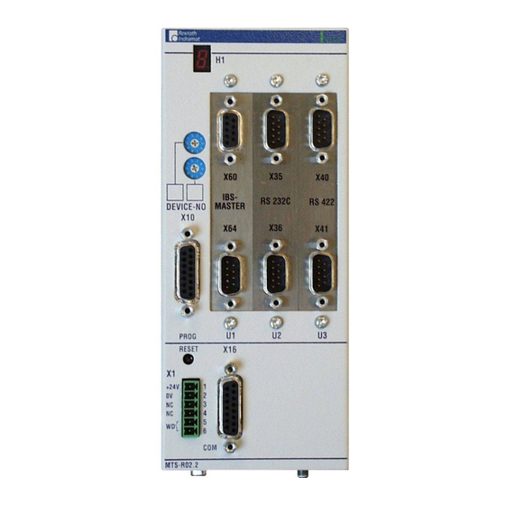
RECO PLC ISP200-R/G2 RECO PLC ISP200-R RECO PLC ISP200-R Front View MTS-R01.2 and MTS-R02.2 RECO RECO IBS- IBS- RS 232C RS 422 MASTER MASTER DEVICE-NO DEVICE-NO PROG PROG RESET RESET +24V +24V MTS-R01.2 MTS-R02.2 MTS-R_Kurz.FH7 MTS-R_Kurz.FH7 Fig. 1-1: MTS-R01.2 and MTS-R02.2 DOK-CONTRL-MTS-R0*.2G2-PR01-EN-P... -
Page 8: Brief Description Of The Isp200-R
RECO PLC ISP200-R RECO PLC ISP200-R/G2 Brief Description of the ISP200-R The ISP200-R RECO PLC is an efficient PLC in RECO format and is compatible with the PLC in the MTC200 control system. It can be used as stand alone PLC or, in connection with an MTC-R, as slave PLC. The PROG interface, which can be operated in the RS232 or in the RS422 mode, allows the connection to a PC or a programming device. -
Page 9: Important Directions For Use
RECO PLC ISP200-R/G2 Important Directions for Use Important Directions for Use Appropriate Use Introduction Rexroth products represent state-of-the-art developments manufacturing. They are tested prior to delivery to ensure operating safety and reliability. The products may only be used in the manner that is defined as appropriate. -
Page 10: Areas Of Use And Application
Important Directions for Use RECO PLC ISP200-R/G2 Areas of Use and Application The MTS-R01.2 and the MTS-R02.2 of Rexroth are intended to be plugged in the RECO02 module carrier system. The ISP200-R is designed for use in the following cases: •... -
Page 11: Safety Instructions For Electric Drives And Controls
RECO PLC ISP200-R/G2 Safety Instructions for Electric Drives and Controls Safety Instructions for Electric Drives and Controls Introduction Read these instructions before the initial startup of the equipment in order to eliminate the risk of bodily harm or material damage. Follow these safety instructions at all times. -
Page 12: Hazards By Improper Use
Safety Instructions for Electric Drives and Controls RECO PLC ISP200-R/G2 Hazards by Improper Use High voltage and high discharge current! Danger to life or severe bodily harm by electric shock! DANGER Dangerous movements! Danger to life, severe bodily harm or material damage by unintentional motor movements! DANGER High electrical voltage due to wrong... -
Page 13: General Information
RECO PLC ISP200-R/G2 Safety Instructions for Electric Drives and Controls General Information • The Bosch Rexroth AG is not liable for damages resulting from failure to observe the warnings provided in this documentation. • Read the operating, maintenance and safety instructions in your language before starting up the machine. -
Page 14: Protection Against Contact With Electrical Parts
Safety Instructions for Electric Drives and Controls RECO PLC ISP200-R/G2 • Operation is only permitted if the national EMC regulations for the application are met. The instructions for installation in accordance with EMC requirements can be found in the documentation "EMC in Drive and Control Systems". -
Page 15: Protection Against Electric Shock By Protective Low Voltage (Pelv)
RECO PLC ISP200-R/G2 Safety Instructions for Electric Drives and Controls To be observed with electrical drive and filter components: High electrical voltage on the housing! High leakage current! Danger to life, danger of injury by electric shock! ⇒ Connect the electrical equipment, the housings of all DANGER electrical units and motors permanently with the safety conductor at the ground points before power is... - Page 16 Safety Instructions for Electric Drives and Controls RECO PLC ISP200-R/G2 Dangerous movements can occur immediately after equipment is switched on or even after an unspecified time of trouble-free operation. The monitoring in the drive components will normally be sufficient to avoid faulty operation in the connected drives.
-
Page 17: Protection Against Magnetic And Electromagnetic Fields During Operation And Mounting
RECO PLC ISP200-R/G2 Safety Instructions for Electric Drives and Controls ⇒ Disconnect electrical power to the equipment using a master switch and secure the switch against reconnection for: - maintenance and repair work - cleaning of equipment - long periods of discontinued equipment use ⇒... -
Page 18: Protection Against Contact With Hot Parts
Safety Instructions for Electric Drives and Controls RECO PLC ISP200-R/G2 Protection Against Contact with Hot Parts Housing surfaces could be extremely hot! Danger of injury! Danger of burns! ⇒ Do not touch housing surfaces near sources of heat! Danger of burns! CAUTION ⇒... -
Page 19: Battery Safety
RECO PLC ISP200-R/G2 Safety Instructions for Electric Drives and Controls 3.11 Battery Safety Batteries contain reactive chemicals in a solid housing. Inappropriate handling may result in injuries or material damage. Risk of injury by incorrect handling! ⇒ Do not attempt to reactivate discharged batteries by heating or other methods (danger of explosion and cauterization). - Page 20 3-10 Safety Instructions for Electric Drives and Controls RECO PLC ISP200-R/G2 Notes DOK-CONTRL-MTS-R0*.2G2-PR01-EN-P...
-
Page 21: Technical Data
RECO PLC ISP200-R/G2 Technical Data Technical Data General Features Mounting in the control cabinet: Module carrier RMB02.2 / RMB04.2 Housing dimensions (W x H x D): MTS-R01.2 = 41.5 x 192 x 150 mm MTS-R02.2 = 83.7 x 192 x 150 mm Weight: MTS-R01.2 = 1.1 kg MTS-R02.2 = 1.3 kg... -
Page 22: Emc
Technical Data RECO PLC ISP200-R/G2 Emitted interference according to EN 55022 Class A (industrial environment) Noise immunity according to IEC 61000-4-2 (ESD) Assessment criterion B Noise immunity according to IEC 61000-4-4 (burst) Assessment criterion B Noise immunity according to IEC 61000-5-5 (surge) Assessment criterion B Interfaces Programming interface (PROG) -
Page 23: Dimensions
RECO PLC ISP200-R/G2 Technical Data Dimensions MTS-R01.2 and MTS-R02.2 41,5 83,7 RECO RECO IBS- IBS- RS 232C RS 422 MASTER DEVICE-NO MASTER DEVICE-NO PROG PROG RESET RESET +24V +24V MTS-R01.2 MTS-R02.2 M5 grounding bolt ca. 230 182,5 54,5 Top hat rail TS 35 x 17 x 15 MTS-R_Maß.FH7 MTS-R_Maß.FH7... -
Page 24: Installation Sizes Of The Rmb02.2-02 Module Carrier
Technical Data RECO PLC ISP200-R/G2 Installation Sizes of the RMB02.2-02 Module Carrier 54,5 Locking screw for locking the chassis on the top hat rail Top hat rail TS35 x27 x15 RMB02.2-2_Maß.FH7 RMB02.2_Maß.FH7 Fig. 4-2: RMB02.2-02 module carrier RMB02.2-2+02.2-4_Maß.FH7 RMB02.2-02+02.2-04_Maß.FH7 Fig. 4-3: Connection of one RMB02.2-02 and several RMB02.2-04 module carriers DOK-CONTRL-MTS-R0*.2G2-PR01-EN-P... -
Page 25: Installation Sizes Of The Rmb02.2-04 Module Carrier
RECO PLC ISP200-R/G2 Technical Data Installation Sizes of the RMB02.2-04 Module Carrier Locking screw for locking the chassis on the top hat rail 54.5 Top hat rail TS 35 x 27 x15 RMB02.2-04_Maß.FH7 RMB02.2-04_Maß.FH7 Fig. 4-4: RMB02.2-04 module carrier RMB02.2-04+02-04_Maß.FH7 RMB02.2-04+02-04_Maß.FH7 Fig. - Page 26 Technical Data RECO PLC ISP200-R/G2 DOK-CONTRL-MTS-R0*.2G2-PR01-EN-P...
-
Page 27: Communication
RECO PLC ISP200-R/G2 Communication Communication Parameterization of the PROG Interface For setting the parameters of the PROG interface, a DIP switch (see Fig. 5-1) is provided on the upper side inside the housing of the ISP200-R. This DIP switch permits to set the operating mode (RS232/RS422/RS485, baud rate, etc.). -
Page 28: Parameterization Of The Com Interface
Communication RECO PLC ISP200-R/G2 Parameterization of the COM Interface As a standard, the multimode COM user interface is delivered as an RS232 interface. The parameters for RS422/RS485 operation are set by programming the OPEN_COM standard PLC function block and by assigning the COM FB input correspondingly. -
Page 29: Addressing
RECO PLC ISP200-R/G2 Communication Addressing The BT bus is addressed by assigning a logic user number in the I/O editor of the PLC programming interface WinPCL. Each input core image storage as well as each output core image storage is assigned its own logic address. - Page 30 Communication RECO PLC ISP200-R/G2 DOK-CONTRL-MTS-R0*.2G2-PR01-EN-P...
-
Page 31: Startup
RECO PLC ISP200-R/G2 Startup Startup Slot Addressing of the Module Carriers Before installation of the modules, the slot addresses of the maximum 4 connectable RMB02.2-04 module carriers must be assigned. To achieve this, a DIP switch is provided on the bus board of the module carriers. Depending on the module concerned, this switch must be set to the corresponding module carrier number (module carrier address 00.03, see following graphic diagram). -
Page 32: Installation Instructions
Startup RECO PLC ISP200-R/G2 Installation Instructions Before the ISP200-R can be installed, the module carriers must first be mounted. These module carriers must be fitted with the ISP200-R and, as required, with the pertinent I/O modules (RECO02 modules). Installation of Module Carriers Install the RMB02.2-02 and RMB02.2-04 module carriers by engaging them on a DIN TS 35x27x15 top hat rail and by fixing them by means of a locking screw. -
Page 33: Installation Of Modules
RECO PLC ISP200-R/G2 Startup RMB02.2-02 4x RMB02.2-04 for taking up an with a total of 16 module spaces for MTS-R01 + MTC-R01 or taking up various I/O modules RMB02.2-02_Anord.FH7 a gateway module + MTS-R01 Fig. 6-3: Maximum number of RMB02.2-02 and RMB02.2-04 carriers fitted Installation of Modules Starting with an MTS-R in slot 0 (to the left), the modules must be fitted in the RMB02.2-04 module carrier and fixed with 2 locking screws each. -
Page 34: Grounding
Startup RECO PLC ISP200-R/G2 Grounding For grounding the control and shielding the electronics, a grounding line of at least 6 mm² must be wired from the grounding bolt of the control to the central grounding point of the machine. Wiring to further users of the machine must be established as star wiring (see Fig. -
Page 35: Connection Of Supply Voltage And Watchdog
RECO PLC ISP200-R/G2 Startup Connection of Supply Voltage and Watchdog In order to ensure correct operation of the ISP200-R, the supply voltage may, under no circumstances, drop below +18 VDC, since this would cause the POWER-FAIL signal to respond. This, in turn, would stop the PLC operating program and the seven-segment display would indicate a “minus”... -
Page 36: Recobus In The Plc Memory
Startup RECO PLC ISP200-R/G2 RecoBus in the PLC Memory As the I/Os in the PLC memory are gapless imaged some principles have to be considered while programming the inputs and outputs. The PLC always requires 4 bytes in the input area for the diagnostic double word. The diagnostic double word permits an exact diagnosis of the connected modules (see 6.5 RecoBus Diagnosis). -
Page 37: Recobus Diagnosis
RECO PLC ISP200-R/G2 Startup RecoBus Diagnosis For RecoBus diagnosis, the MTS-R provides a double word for input information (%ID*.0). This double word serves to display error and status information. It is represented to the user in the PLC I/O editor on Byte 0-3. This double word should always be a part of the PLC user program, thus allowing quick reactions to error messages of the RecoBus. -
Page 38: Error Detection By The User
Startup RECO PLC ISP200-R/G2 Error Detection by the User Error detection: Slot address Error no. 15 14 13 12 11 10 9 8 7 6 5 4 3 2 1 0 Error no. Slot no. 1 = Module x has detected error y 1 = Error y occurred in module x... -
Page 39: External Voltage Monitoring
RECO PLC ISP200-R/G2 Startup External Voltage Monitoring The transistor output modules RMA02.2-16-DC024-200 and RMA02.2-32- DC024-050 are provided with a 24-V voltage monitoring unit. One monitoring bit on a bit strip of 1-word width is made available per module. A “1” on bit 16 indicates that one or more 24-V supply voltages are missing (the bit number corresponds to the slot number). -
Page 40: Status Information And Error Diagnosis
6-10 Startup RECO PLC ISP200-R/G2 Status Information and Error Diagnosis Indication of Operating States A diagnosis of the ISP200-R can be made using the seven-segment display H1. The various states are displayed via the one-digit error codes shown below. Code Description Power-Fail signal triggered (the control must be reset) Ready for operation (PLC is running) -
Page 41: Battery
6-11 RECO PLC ISP200-R/G2 Startup Battery If an ISP200-R is not operated or is stored for more than 6 months, user- specific PLC data may get lost because of a self-discharge of the battery. The following data is involved: Data involved •... - Page 42 6-12 Startup RECO PLC ISP200-R/G2 DOK-CONTRL-MTS-R0*.2G2-PR01-EN-P...
-
Page 43: Reco Plc Mts-R01.2
RECO PLC ISP200-R/G2 RECO PLC MTS-R01.2 RECO PLC MTS-R01.2 Brief Description The MTS-R01.2 is an efficient PLC in small-size format and in IP 20 de- sign. It requires 1 slot in the RMB02.2 module carrier and can be used as a stand alone PLC with the corresponding I/Os or together with motion control as a combined CNC-PLC system. -
Page 44: Application Example
RME 02.2-32-DC024 RMA02.2-32-DC 024-050 RMA02.2-32-DC 024-050 RS422 IKB0015 RS422 max. 400m IKB0015 max. 400m IKS 188 max. 15m S Y S T E M200 BT V05 SYSTEM200 BTC06 BTV05 BTC06 10 20 Appl_MTS-R01.FH7 Fig. 7-2: MTS-R01.2 with INTERBUS connection DOK-CONTRL-MTS-R0*.2G2-PR01-EN-P... -
Page 45: Type Code
RECO PLC ISP200-R/G2 RECO PLC MTS-R01.2 Type Code Fig. 7-3: MTS-R01.2 type code DOK-CONTRL-MTS-R0*.2G2-PR01-EN-P... - Page 46 RECO PLC MTS-R01.2 RECO PLC ISP200-R/G2 DOK-CONTRL-MTS-R0*.2G2-PR01-EN-P...
-
Page 47: Reco Plc Mts-R02.2
RECO PLC ISP200-R/G2 RECO PLC MTS-R02.2 RECO PLC MTS-R02.2 Brief Description The MTS-R02.2 is an efficient PLC in small-size format and in IP 20 design. It requires 2 slots in the RMB02.2 module carrier and can be used as a stand alone PLC with the corresponding I/Os or together with motion control as a combined CNC-PLC system. -
Page 48: Application Example
RECO PLC MTS-R02.2 RECO PLC ISP200-R/G2 Application Example INTERBUS I/O´s SYSTEM200 BTV05 Q*.3.0 *.3.0 *.3.0 Q*.3.1 *.3.1 *.3.1 Q*.3.2 *.3.2 *.3.2 Q*.3.3 *.3.3 *.3.3 BTV05 Q*.3.4 *.3.4 *.3.4 DIAG Q*.1.0 Q*.1.0 Q*.3.5 *.1.0 *.3.5 *.3.5 Q*.3.6 *.3.6 *.3.6 Q*.1.1 Q*.1.1 *.1.1... -
Page 49: Type Code
RECO PLC ISP200-R/G2 RECO PLC MTS-R02.2 Type Code Fig. 8-3: MTS-R02.2 type code DOK-CONTRL-MTS-R0*.2G2-PR01-EN-P... - Page 50 RECO PLC MTS-R02.2 RECO PLC ISP200-R/G2 DOK-CONTRL-MTS-R0*.2G2-PR01-EN-P...
-
Page 51: Interbus Master Connection
RECO PLC ISP200-R/G2 INTERBUS Master Connection INTERBUS Master Connection Brief Description Setting of the I/O-Adresse RS 232 INTERBUS LK IBM 2 INTERBUS module (B1) X60 INTERBUS interface (remote bus) IBS- MASTER X64 INTERBUS diagnoses interface RS232 C LK IBM2_Anschl.FH7 Fig. 9-1: P.C.B. LK IBM 2 The printed circuit board IBM 2 is an INTERBUS master connection of the generation in PC104 format. -
Page 52: Setting Of The I/O Address
INTERBUS Master Connection RECO PLC ISP200-R/G2 The P.C.B. LK IBM 2 possesses the following features: INTERBUS protocol (DIN E 19 258), up to 256 bus segments, up to 16 user levels, up to 512 users per configuration, up to 4096 inputs and 4096 outputs per configuration (512 bytes), up to 32 INTERBUS loop users per bus segment, CMD G4 support. -
Page 53: Interface Assignment
RECO PLC ISP200-R/G2 INTERBUS Master Connection Interface Assignment Signal name Signal name TxD - Transmit Data RxD - Receive Data SGND - Ground RTS - Ready To Send CTS - Clear To Send Fig. 9-4: Pin assignment of the INTERBUS diagnosis interface X64 (RS232 C) Signal name Signal name RBST... - Page 54 INTERBUS Master Connection RECO PLC ISP200-R/G2 DOK-CONTRL-MTS-R0*.2G2-PR01-EN-P...
-
Page 55: Profibus Dp Connection
10-1 RECO PLC ISP200-R/G2 PROFIBUS DP Connection PROFIBUS DP Connection 10.1 Brief Description of Master and Slave Connection STA ERR RUN RDY LK DPM01 or LK DPS01 Default setting of the I/O address $CA000 1 1 0 0 1 0 1 PROFIBUS-DP PROFIBUS-DP Slave module (P2) -
Page 56: Setting The I/O Addresses
10-2 PROFIBUS DP Connection RECO PLC ISP200-R/G2 The configuration and commissioning of the LK DPM/DPS01 occurs by the system configurator SyConPB (see DOK-CONTRL-SYCON****DP). For the configuration the interface cable IKS0106 is required. The PROFIBUS DP master connection P.C.B. DPM01 permits connection of up to 32 PROFIBUS DP users within one bus segment. -
Page 57: Status And Diagnosis Information
10-3 RECO PLC ISP200-R/G2 PROFIBUS DP Connection 10.3 Status and Diagnosis Information After having been switched on, the P.C.B.s DPM01 and DPS01 perform a self-test. After the initialization phase of this test (2 to 3 seconds), the two 5'< LEDs turn dark, and the yellow LED emits light if the 5'<... -
Page 58: Interface Assignment
10-4 PROFIBUS DP Connection RECO PLC ISP200-R/G2 10.5 Interface Assignment The assignments of the interfaces of the PROFIBUS connections are as follows: Signal name Signal name RxD - Receive Data TxD - Transmit Data DTR - Data Terminal Ready GND - Operating ground RTS - Ready To Send CTS - Clear To Send Fig. -
Page 59: Devicenet Master Connection
11-1 RECO PLC ISP200-R/G2 DeviceNet Master Connection DeviceNet Master Connection 11.1 Brief Description Diagnostic display LK DNM03 Default setting of the I/O address $CE000 DeviceNet master module (V1) X80 DeviceNet interface (Master) X84 DeviceNet diagnostic interface RS232 C (projecting interface) LK DNM3_Anschl.FH7 LK DNM3_Anschl.EPS Fig. -
Page 60: Setting Of The I/O Address
11-2 DeviceNet Master Connection RECO PLC ISP200-R/G2 The total length of the bus cable depends on the cable type or on the transmission rate and must not exceed the following lengths: Baud rate Max. cable length for cable type Thick cable Thin cable Thick/thin cable 125 kbits/s... -
Page 61: Status And Diagnostic Displays
11-3 RECO PLC ISP200-R/G2 DeviceNet Master Connection 11.3 Status and Diagnostic Displays With the start of the DNM03 a self-test is started, whereby the yellow RDY LED lights up after the initialization time (2-3 seconds) after an error-free test cycle. Otherwise, the RDY LED starts to flash and the program execution is interrupted. -
Page 62: Interface Assignment
11-4 DeviceNet Master Connection RECO PLC ISP200-R/G2 11.5 Interface Assignment Signal name Signal name RxD - Receive Data TxD - Transmit Data DTR - Data Terminal Ready GND - Ground RTS - Ready To Send CTS - Clear To Send Fig. -
Page 63: Serial Interfaces
12-1 RECO PLC ISP200-R/G2 Serial Interfaces Serial Interfaces 12.1 Brief Description The P.C.B. SIO 04-B provides the PLC user program with up to four serial interfaces (RS232 and RS422/485) for general use. Operation of the serial interfaces is interrupt-controlled via the PLC firmware. The send and receive data of each interface are made available in buffers of 256 bytes length each. -
Page 64: Address And Interrupt Settings
12-2 Serial Interfaces RECO PLC ISP200-R/G2 12.2 Address and Interrupt Settings RS 232 C RS 232 C LK SIO 04-B RS 422 RS 422 W58/59/60 W61 W62 LK SIO04-B_Einstell.FH7 Fig. 12-2: Jumper settings on the P.C.B. SIO 04-B 12.3 Function Blocks To be able to address the serial interfaces of the peripheral equipment the PLC programming system provides the following firmware function blocks:... -
Page 65: Technical Data
12-3 RECO PLC ISP200-R/G2 Serial Interfaces 12.4 Technical Data Supply Supply voltage: 4.5 to 5.5 VDC Power consumption: Max. 250 mA Interface data Input capacity: Max. 15 pF Input leakage current: Max. 5 µA Output capacity: Min. 150 pF Output current (switching actively 0): Min. - Page 66 12-4 Serial Interfaces RECO PLC ISP200-R/G2 DOK-CONTRL-MTS-R0*.2G2-PR01-EN-P...
-
Page 67: Networking
13-1 RECO PLC ISP200-R/G2 Networking Networking 13.1 Networking via the PROG and COM Interfaces The PROG interface of the ISP200-R can be operated as a point-to-point connection (RS232/RS422) and as a bus (RS485). Using the RS485 bus, a maximum of 16 controls can be networked. This is achieved by assign- ing a device number between 0 and 15. -
Page 68: Isp200-R In Connection With The Btv20/30
13-2 Networking RECO PLC ISP200-R/G2 13.2 ISP200-R in Connection with the BTV20/30 The BTV20/30 is equipped with a Rexroth SIS interface, which permits networking of a BTV20/30 with several ISP200-R. This interface can be used to establish an RS485 bus system (see Fig. 13-3). Fig. -
Page 69: Connection Of Operator Terminals
X16 and X40/41, which permit RS422 or RS485 operation. Only one compact operator terminal can be connected to an RS422 interface (see Fig. 14-1). MTS-R BTV06 (BTV05) RECO SYSTEM200 BTV06 RS422 operation either IB S - at X16 and/or at X40/41 RS 232C... -
Page 70: Fig. 14-2: Mts-R With Compact Operator Terminals Via An Rs485 Interface
During RS485 operation, two operator terminals can be connected in cascade per interface (see Fig. 14-2). Hence, a maximum of six operator terminals can be connected during RS485 operation. MTS-R BTV06 (BTV05) RECO SYSTEM200 BTV06 RS485 operation either IB S - at X16 and/or at X40/41 RS 232C... -
Page 71: Applications With The Btc06
IKB0015 Additional MTS-R BTA20.3 BTA10/20 units RS232 RECO IKB0193 10 20 E-STOP RS232 operation either an X35 and/or at X3t SYSTEM200 BTC06 IB S - RS 232C RS 422 MACHINE CONTROL DEVICE-NO MASTER BTC06 10 20 PROG RESET +24V RS422 IKS 190 MTS-R02.2... -
Page 72: Fig. 14-4: Mts-R With Via An Rs422 Interface
Connection of Operator Terminals RECO PLC ISP200-R/G2 RS422 IKB0015 Additional BTA20.3 MTS-R BTA10/20 units RS422 RECO IKB0016 10 20 E-STOP SYSTEM200 BTC06 BTC06 IB S - RS 232C RS 422 MACHINE CONTROL MASTER 10 20 DEVICE-NO RS422 IKB0015 RS422 PROG... -
Page 73: Accessories
15-1 RECO PLC ISP200-R/G2 Accessories Accessories 15.1 Selection List of Connectors and Ready-Made Cables Ordering name of ready- Counter- REXROTH cable Execution of made cables connector on cable end the device INS439 INS526 IKB0005 MN: 278 141, 2 m INK572 MN: 278 144, 5 m MN: 278 142, 10 m MN: 278 143, 15 m... - Page 74 15-2 Accessories RECO PLC ISP200-R/G2 INS645 INS526 IKB0016/000,0 INK234 MN: 282 871 (RS422, max. 400 m) 9-pin female connector 15-pin male connector INS619 INS619 IKB0017/000,0 INK572 MN: 282 872 (RS485, max. 400 m) 15-pin male 15-pin male connector connector INS619 INS526 IKB0018/000,0 INK572...
-
Page 75: Fig. 15-1: Mts-R Accessories
15-3 RECO PLC ISP200-R/G2 Accessories INS0541/K01 INS0541/K01 IKB0033 IKB0033 IKB0033/000,0 INK0698 MN: 291 808 (PROFIBUS, max. 1000 m) 9-pin male 9-pin male connector connector INS0541/K01 IKB0034 IKB0034 IKB0034/000,0 INK0698 MN: 291 809 (PROFIBUS, max. 1000 m) 9-pin male connector INS525 INS526 IKS0056/000,0 INK234... -
Page 76: Labeling Of I/O Modules
15-4 Accessories RECO PLC ISP200-R/G2 15.2 Labeling of I/O Modules A labeling package (SUP-M03-RECO) is available for additionally labeling the RECO02 I/O modules. This package consists of 16 carrier foils, 10 labeling foils with 6 adhesive strips each, and the labeling software. The carrier foil can be glued on the left or right of the module housings. -
Page 77: List Of Figures
16-1 RECO PLC ISP200-R/G2 List of Figures List of Figures Fig. 1-1: MTS-R01.2 and MTS-R02.2 1-1 Fig. 3-1: Hazard classification (according to ANSI Z535) 3-1 Fig. 4-1: Dimensional drawing of MTS-R01.2 and MTS-R02.2 4-3 Fig. 4-2: RMB02.2-02 module carrier 4-4 Fig. - Page 78 16-2 List of Figures RECO PLC ISP200-R/G2 Fig. 9-3: Technical data 9-2 Fig. 9-4: Pin assignment of the INTERBUS diagnosis interface X64 (RS232 C) 9-3 Fig. 9-5: Pin assignment of the INTERBUS interface X60 (remote bus) Fig. 10-1: PROFIBUS connections 10-1 Fig.
-
Page 79: Service & Support
17-1 RECO PLC ISP200-R/G2 Service & Support Service & Support 17.1 Helpdesk Unser Kundendienst-Helpdesk im Hauptwerk Lohr Our service helpdesk at our headquarters in Lohr am am Main steht Ihnen mit Rat und Tat zur Seite. Main, Germany can assist you in all kinds of inquiries. Sie erreichen uns Contact us +49 (0) 9352 40 50 60... -
Page 80: Kundenbetreuungsstellen - Sales & Service Facilities
C A L L E N T R Y C E N T E R H O T L I N E ERSATZTEILE / SPARES Rexroth Indramat GmbH MO – FR MO – FR verlängerte Ansprechzeit Bgm.-Dr.-Nebel-Str. 2 / Postf. 1357... - Page 81 Belgium - Belgien Denmark - Dänemark Bosch Rexroth GmbH Bosch Rexroth GmbH Bosch Rexroth AG BEC A/S Bereich Indramat Gesch.ber. Rexroth Indramat Electric Drives & Controls Zinkvej 6 Stachegasse 13 Industriepark 18 Industrielaan 8 8900 Randers 1120 Wien 4061 Pasching 1740 Ternat Tel.:...
- Page 82 17-4 Service & Support RECO PLC ISP200-R/G2 Europa (Ost) - Europe (East) vom Ausland: (0) nach Landeskennziffer weglassen from abroad: don’t dial (0) after country code Czech Republic - Tschechien Czech Republic - Tschechien Hungary - Ungarn Poland – Polen DEL a.s.
- Page 83 Indonesia - Indonesien Bosch Rexroth (India) Ltd. Bosch Rexroth (India) Ltd. Bosch Rexroth (India) Ltd. PT. Rexroth Wijayakusuma Rexroth Indramat Division Rexroth Indramat Division 1st Floor, S-10 Building # 202, Cilandak Plot. A-58, TTC Industrial Area Plot. 96, Phase III Green Park ext.
- Page 84 USA SERVICE-HOTLINE Headquarters - Hauptniederlassung Bosch Rexroth Corporation Bosch Rexroth Corporation Bosch Rexroth Corporation Rexroth Indramat Division Rexroth Indramat Division - 7 days x 24hrs - Rexroth Indramat Division Central Region Technical Center Southeastern Technical Center 5150 Prairie Stone Parkway...
- Page 86 2 9 4 6 9 1...
Need help?
Do you have a question about the SYSTEM200 and is the answer not in the manual?
Questions and answers