Sign In
Upload
Manuals
Brands
Rexroth Indramat Manuals
Controller
CLM1.4
Rexroth Indramat CLM1.4 Manuals
Manuals and User Guides for Rexroth Indramat CLM1.4. We have
1
Rexroth Indramat CLM1.4 manual available for free PDF download: Manual
Rexroth Indramat
CLM1.4
Manual
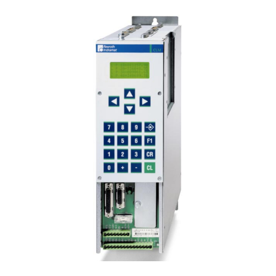
Rexroth Indramat CLM1.4 Manual (274 pages)
2 (4) Axis Positioning Control with Profibus
Brand:
Rexroth Indramat
| Category:
Controller
| Size: 2.75 MB
Table of Contents
Table of Contents
4
1 System Setup
12
The CLM at a Glance
12
Mechanical Data
13
Saving Data
14
System Overview
15
2 Important Directions for Use
16
Appropriate Use
16
Introduction
16
Areas of Use and Application
17
Inappropriate Use
17
3 Safety Instructions for Electric Drives and Controls
18
Introduction
18
Explanations
18
Hazards by Improper Use
19
General Information
20
Protection against Contact with Electrical Parts
22
Protection against Electric Shock by Protective Low Voltage (PELV)
23
Protection against Dangerous Movements
24
Protection against Magnetic and Electromagnetic Fields During Operation and Mounting
26
Protection against Contact with Hot Parts
27
3.10 Protection During Handling and Mounting
27
3.11 Battery Safety
28
3.12 Protection against Pressurized Systems
28
4 Display and Operating Devices
30
General Information about the CTA
30
CLM Display
31
Description of the Input Keys
32
Data Entry Keys
32
Control Keys
32
Description of the Display Modes
33
Software Version / Status Diagnostics
34
Material Velocity
35
Variable Display
35
Display: Inputs / Outputs / Marker Flags
36
Counter Display
36
Position Display
37
Operation Data
39
Program Input
40
Parameter Input
41
5 Writing the User Program
42
Overview of All User Commands
42
General Information
44
Program Input
45
Input Via the Keypad
45
Loading Via the Serial Port
47
Starting the User Program
47
Stopping the User Program
47
Variables
48
Available Variables
49
System Variables
49
Axis Variables
50
Description of Commands
51
ACC - Acceleration Change
51
AEA - Bit Set/Clear
52
AEO - Acceleration Override Command
52
AKN - Compare Bit
53
AKP - Compare Byte
54
APE - Byte Set/Clear
55
BAC - Branch Conditional on Count
56
BCE - Branch Conditional on Bit
57
BIC - Branch Conditional on Bit Field Value
57
BIO - Branch Conditional on Byte Compare
58
BPA - Branch Conditional on Byte
59
CID - Change Instruction Data
60
CIO - Copy Bit Fields
60
CLC - Clear Counter
61
CON - Continuous Operation
62
COU - Count
62
CPJ - Compare and Jump
64
CPL - Clear Position Error
64
CPS - Compare and Set a Bit
65
CST - Clear Subroutine Stack Level
65
CVT - Convert Variable <- -> Marker
66
FAK - Length Scaling Factor
69
FOL - Slave Axis
70
HOM - Home Axis
71
JMP - Jump Unconditional
72
JSR - Jump to Subroutine
72
JST - Jump, Unconditional with Immediate Stop
73
JTK - Program Jump in Parallel Task
73
MAT - Mathematics
74
NOP - no Operation
74
PBK - Stop Motion
75
POA - Positioning, Absolute
76
POI - Positioning, Incremental
77
PSA - Positioning Absolute with In-Position
77
PSI - Positioning Incremental with In-Position
78
REP - Jump on Max. Search Limit Reached
79
RMI - Registration Mark Interrupt
79
RSV - Restart Vector
82
RTM - Rotary Table Mode
83
RTS - Return from Subroutine
84
SAC - Set Abs. Position Counter
85
SET - Set Variable
86
SRM - Drive to Registration Mark
86
VCC - Velocity Change Command
88
VEO - Velocity Override Command
90
WAI - Wait (Time Delay)
93
6 Logic Task
94
Tabular View
94
Load, Save, Set and Reset Assignments
94
Commands for Loading and Saving
94
Set and Reset Commands
94
Logical Assignments
95
AND Logic
95
OR Logic
96
XOR Logic
97
7 Functions
98
Operating Modes
98
Measuring Wheel Mode
98
Velocity Override
100
Override Via Analog Input
100
Override Via Gray-Code Inputs
101
Override Via Binary-Code Inputs
102
Vector Programming
103
Manual Vector
103
Interrupt Vector
104
Multitasking
105
Slave Axis
107
Mechanical Data
108
Mechanical Transmission Elements
108
Modulo Function
109
Decade Switch 'IDS01
110
Homing
111
General Information
111
Option 1: Homing to a Home Switch
112
Placement of the Home Switch
113
Activation of the Home Switch
113
Termination of the Homing Routine
113
Option 2: Homing Without a Home Switch
114
Position Loop Reset (Electrical Release)
115
7.11 Restart
116
8 Parameters
118
General Information
120
Parameters
120
System Parameters
122
Ax00 Axis X Mode
122
Ax01 Axis X Feed Constant
123
Ax02 Gear
124
Ax03 Axis X Minimum Travel Limit Value
124
Ax04 Axis X Maximum Travel Limit Value
126
Ax05 Axis X Modulo Value
127
Ax06 Axis X Maximum Velocity
128
Ax07 Axis X Jog Velocity
128
Ax08 Axis X Acceleration Rate
129
Ax09 Acceleration / Deceleration Rate
129
Ax10 Jerk Constant
130
Ax11 Axis X Kv Factor
131
Ax12 Axis X Drive Sensitivity
132
Ax13 Reserved (Free)
133
Ax14 Axis X Position Monitoring Window
133
Ax15 Feed Angle Monitoring / Interrupt
135
Ax16 Axis X Encoder Difference
136
Ax17 Axis X Absolute Encoder Monitoring Window
136
Ax18 Reserved (Free)
136
Ax19 Axis X Encoder Data
137
Ax20 Axis X Encoder Type
137
Ax21 Axis X Drive Direction
138
Ax22 Axis X Absolute Encoder Home Position
138
Ax23 Axis X Homing I/O
139
Ax24 Axis X Homing Search Distance
139
Ax25 Axis X Homing Offset
140
Ax26 Reserved
140
Ax27 Axis X Switching Threshold
140
Ax28 Position Window
141
Ax29 Axis X Presignaling
141
Ax30 Axis X Open Feed Roll
141
Ax31 Axis X Measuring Wheel Mode
142
Ax32 Axis X Various Functions
142
Ax33 Axis X Cut Inhibit
142
Ax34 Axis X Cut Vector
143
General Parameters
144
B000 Enable Axis
144
B001 Display
144
B002 RS Interface Format X6
145
B003 RS Interface Functions X6
146
B004 RS Interface Format X8
146
B005 RS Interface Functions X8
146
B006 Fieldbus Time Monitoring
147
B007 Fieldbus Baudrate
147
B008 Fieldbus Formats
148
B009 Reserved (Free)
148
B010 Cycle Time
149
B011 Start Program Instruction - Task 2, Task 3
149
B012 Start Program Instruction - Task 4, Task 5
150
B013 Logic Task
150
B014 Manual Vector
150
B015 Interrupt Vector
151
B016 Re-Start Vector
151
B017 Analog Input / Override
152
Parameters
152
B018 Clear Outputs
153
B019 Memory Display
157
Master Encoder Parameters
158
C000 Master Encoder 1, Measuring Wheel Encoder Data
158
C001 Master Encoder 1, Measuring Wheel Encoder Type
158
C002 Master Encoder 1, Measuring Wheel Encoder Feed Constant (VK)
159
C003 Master Encoder 1, Measuring Wheel Offset
159
C004 Master Encoder 2, Measuring Wheel Encoder Data
159
C005 Master Encoder 2, Measuring Wheel Encoder Type
159
C006 Master Encoder 2, Measuring Wheel Encoder Feed Constant (VK)
159
C007 Master Encoder 2, Measuring Wheel Offset
159
List of CLM Parameters
160
Minimum and Maximum Values for Parameter Input
163
9 Interfaces
164
Inputs, Outputs and Marker Flags
164
Inputs
165
Outputs
170
User-Programmable Outputs
174
Flags
174
Serial Interfaces
176
General Information
176
Connecting the Interface
176
Interface Parameters
179
B002 Interface Format X6
179
B003 Interface Functions X6
180
Description of All Characters Used in the Data String
181
Generating the Checksum
184
Data Transmission
185
Readout of Status Information
192
10 Command Communications
206
10.1 Profibus
206
Fieldbus Parameters
207
Process Data Channel
207
Service Data Channel
211
Parallel Interface
211
Assignment of Profibus Connector X30
212
Profibus LED Diagnostic
212
11 Diagnostic Messages
214
11.1 General Information about Error Identification
214
11.2 Error Code Numbers
214
11.3 Error Descriptions
218
General Error Messages
218
Error Messages for Axes 1 to 4
227
12 Terminal Connection Diagrams
234
12.1 Overview
234
12.2 CLM1.4 Dimensions
235
Power Supply and System Signals for Axes 1 and 2
236
System Signals for Axes 3 and 4
236
System Signals for Axes 1 to 4
237
12.6 Data Interface - Serial Channel a
237
12.7 RS232C/RS485 Data Interface - Serial Channel a
238
12.8 RS485 Data Interface - Serial Channel a
239
12.9 RS232C/RS485 Data Interface - Serial Channel B
240
12.10 Axis 1 Encoder Inputs
241
12.11 Axis 2 Encoder Inputs
242
12.12 Axis 3 Encoder Inputs
243
12.13 Axis 4 Encoder Inputs
244
Inputs - Part 1
245
Inputs - Part 2
246
Inputs - Part 3
247
Outputs - Part 1
248
Outputs - Part 2
249
12.19 Inputs and Outputs
250
12.20 Typecodes
251
13 Installation Notes
252
13.1 General Information
252
13.2 Instructions for Using Cooling Units in Control Cabinets
255
Correct Use of Cooling Units
255
13.3 Safety Instructions for Controls
257
General Information
257
Protection against Contact with Electrical Parts
258
Protection of Safety-Separated Extra Low Voltages
259
Protection against Dangerous Movements
259
Protection During Handling and Installation
260
Protection for Built-In Batteries
261
14 Index
262
15 Service & Support
266
15.1 Helpdesk
266
15.2 Service-Hotline
266
15.3 Internet
266
Vor der Kontaktaufnahme
266
15.5 Kundenbetreuungsstellen - Sales & Service Facilities
267
Advertisement
Advertisement
Related Products
Rexroth Indramat CZM 01.3-02-07
Rexroth Indramat Mannesmann Rexroth CLM-01.3-M
Rexroth Indramat BZM 01.3-01-07
Rexroth Indramat DKC01.3-016-7
Rexroth Indramat DKC01.3-040-7
Rexroth Indramat DKC01.3-100-7
Rexroth Indramat DKC01.3-200-7
Rexroth Indramat DKC02.3-016-7
Rexroth Indramat DKC02.3-040-7
Rexroth Indramat DKC02.3-100-7
Rexroth Indramat Categories
Controller
Control Unit
Amplifier
Industrial Electrical
More Rexroth Indramat Manuals
Login
Sign In
OR
Sign in with Facebook
Sign in with Google
Upload manual
Upload from disk
Upload from URL