Sign In
Upload
Manuals
Brands
Perkins Manuals
Engine
New 1000 Series
Perkins New 1000 Series Manuals
Manuals and User Guides for Perkins New 1000 Series. We have
2
Perkins New 1000 Series manuals available for free PDF download: Workshop Manual
Perkins New 1000 Series Workshop Manual (370 pages)
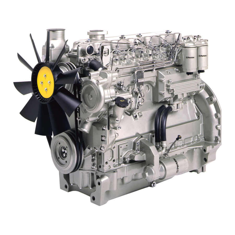
4 and 6 cylinder diesel engines for industrial and agricultural applications
Brand:
Perkins
| Category:
Engine
| Size: 18 MB
Table of Contents
Table of Contents
3
Special Tools
13
1 General Information
15
Introduction
15
Engine Views
16
Engine Identification
17
Safety Precautions
19
Viton Seals
20
Engine Lift Equipment
21
POWERPART Recommended Consumable Products
22
2 Specifications
25
Basic Engine Data
25
Data and Dimensions
26
Thread Sealant
49
Standard Torque Tensions
50
Specific Torque Tensions
51
Compression Test Data
54
3 Cylinder Head Assembly
55
General Description
55
Rocker Cover
56
Operation 3-1 to Remove
56
Operation 3-2 to Fit
57
Rocker Assembly
58
Operation 3-3 to Remove and to Fit
58
Operation 3-4 to Dismantle and to Assemble
59
Operation 3-5 to Inspect and to Correct
59
Valve Tip Clearances
60
Operation 3-6 to Check and to Adjust (Four Cylinder Engines)
60
Operation 3-7 to Check and to Adjust (Six Cylinder Engines)
61
Valve Springs
62
Operation 3-8 to Change the Valve Springs (with Cylinder Head Fitted)
62
Manifolds
64
Operation 3-9 to Remove and to Fit an Intake Manifold
64
Operation 3-10 to Remove and to Fit an Exhaust Manifold (One-Piece)
66
Operation 3-11 to Remove and to Fit an Exhaust Manifold (Three-Piece)
68
Cylinder Head Assembly
70
Operation 3-12 to Remove
70
Operation 3-13 to Fit (Engine Types AJ to AQ and YG to YK)
72
Operation 3-14 to Fit (Engine Types AR and AS)
75
Valves and Valve Springs
78
Operation 3-15 to Remove
78
Operation 3-16 to Fit
79
Operation 3-17 to Inspect and to Correct
80
Valve Guides
81
Operation 3-18 to Inspect
81
Operation 3-19 to Remove
82
Operation 3-20 to Fit
83
Operation 3-21 to Inspect and to Correct
84
Operation 3-22 to Correct a Valve Seat with a Valve Seat Cutter
85
Operation 3-23 to Fit Valve Seat Inserts
87
4 Piston and Connecting Rod Assemblies
89
General Description
89
Big End Bearing
91
Operation 4-1 to Remove
91
Operation 4-2 to Fit
92
Operation 4-3 to Inspect
92
Piston and Connecting Rod
93
Operation 4-4 to Remove
93
Operation 4-5 to Fit
94
Operation 4-6 to Check the Piston Height above the Cylinder Block
96
Piston Rings
97
Operation 4-7 to Remove
97
Operation 4-8 to Fit
98
Piston and Connecting Rod Assembly
99
Operation 4-9 to Dismantle
99
Operation 4-10 to Assemble
100
Operation 4-11 to Check the Length of a Connecting Rod
101
Piston and Piston Rings
102
Operation 4-12 to Inspect
102
Connecting Rod
103
Operation 4-13 to Inspect
103
Partially Finished Small End Bush
104
Operation 4-14 to Remove and to Fit
104
Piston Cooling Jets
105
Operation 4-15 to Remove and to Fit
105
Operation 4-16 to Check the Jet Alignment
106
5 Crankshaft Assembly
107
General Description
107
Crankshaft Pulley
109
Crankshaft Pulley and Damper
110
Operation 5-3 to Fit (Six Cylinder Engines)
111
Operation 5-4 to Inspect
112
Rear Oil Seal Assembly
113
Operation 5-5 to Remove and to Fit (One-Piece Assembly)
113
Operation 5-6 to Remove and to Fit (Two-Piece Assembly)
116
Operation 5-7 to Renew the Rear End Oil Seal (Two-Piece Assembly)
117
Operation 5-8 to Remove and to Fit a Wear Sleeve
118
Thrust Washers
119
Operation 5-9 to Check Crankshaft End-Float
119
Operation 5-10 to Remove
120
Operation 5-11 to Fit
121
Main Bearings
122
Operation 5-12 to Remove (with the Crankshaft in Position)
122
Operation 5-13 to Fit
123
Operation 5-14 to Inspect
123
Crankshaft
124
Operation 5-15 to Remove
124
Operation 5-16 to Fit
125
Operation 5-17 to Inspect
127
Balancer Unit
128
Operation 5-18 to Remove and to Fit
128
Operation 5-19 to Dismantle
129
Operation 5-20 to Assemble
131
Operation 5-21 to Inspect
134
Operation 5-22 to Remove and to Fit the Needle Roller Bearings for the Drive Shaft
135
Operation 5-23 to Remove and to Fit the Bushes for the Balance Weights
136
6 Timing Case and Drive Assembly
137
General Description
137
Timing Case Cover
138
Operation 6-2 to Fit
139
Front Oil Seal
141
Operation 6-4 to Fit
142
Idler Gear and Hub
145
Operation 6-6 to Remove
145
Operation 6-7 to Fit
147
Idler Gear and Hub for the Compressor
149
Operation 6-9 to Fit
150
Fuel Pump Gear
151
Operation 6-10 to Remove
151
Operation 6-11 to Fit
153
Camshaft Gear
155
Operation 6-12 to Remove and to Fit
155
Crankshaft Gear
156
Operation 6-13 to Remove and to Fit
156
Timing Case
157
Operation 6-14 to Remove
157
Operation 6-15 to Fit
158
Camshaft and Tappets
160
Operation 6-16 to Remove
160
Operation 6-17 to Fit
161
7 Cylinder Block Assembly
163
General Description
163
Cylinder Block
164
Operation 7-2 to Assemble
165
Operation 7-3 to Inspect
166
Operation 7-4 to Remove and to Fit a New Type 'D' Plug to the Tappet Chamber
167
Cylinder Liner
169
Operation 7-6 to Remove
170
Operation 7-7 to Fit a Service Liner
172
Operation 7-8 to Fit a Partially Finished Liner
175
Cylinder Bore, Engine Types AR and as
178
8 Engine Timing
179
General Description
179
Operation 8-1 to Set Number 1 Piston to TDC on the Compression Stroke
181
Operation 8-2 Another Method to Set Number 1 Piston to TDC
182
Operation 8-3 to Check the Valve Timing
183
Operation 8-4 to Check the Timing of the Fuel Injection Pump
184
9 Aspiration System
185
General Description
185
Turbocharger
187
Operation 9-1 to Remove
187
Operation 9-2 to Fit
188
Operation 9-3 to Clean the Impeller and the Compressor Casing
190
Operation 9-4 to Remove and to Fit the Actuator Assembly of the Waste-Gate Unit
191
Operation 9-5 to Check and Adjust the Operation of the Waste-Gate
192
Turbocharger Faults
193
List of Possible Causes
194
Open Engine Breather
195
Operation 9-6 to Clean and to Renew
195
Operation 9-7 to Inspect
197
Closed Engine Breather
198
Operation 9-8 to Renew the Breather Valve Assembly
199
10 Lubrication System
201
General Description - Four Cylinder Engine Lubrication System
201
General Description - Six Cylinder Engine Lubrication System
202
Filter Canister
205
Filter Head
206
Operation 10-2 to Remove and to Fit
206
Sump
207
Operation 10-3 to Remove and to Fit
207
Oil Strainer and Suction Pipe
208
Operation 10-4 to Remove and to Fit
208
Operation 10-5 to Inspect and to Correct
209
Lubricating Oil Pump
210
Operation 10-6 to Remove
210
Operation 10-7 to Fit
211
Operation 10-8 to Inspect
212
Lubricating Oil Pump Idler Gear Shaft
213
Operation 10-9 to Remove (Six Cylinder Engines)
213
Operation 10-10 to Fit (Six Cylinder Engines)
215
Operation 10-11 to Remove and to Fit (Four Cylinder Engines)
216
Relief Valve
217
Operation 10-12 to Remove and to Fit
217
Operation 10-13 to Dismantle and to Assemble
218
Operation 10-14 to Inspect
218
Flexible Oil Pipes
219
Operation 10-15 to Remove
219
Operation 10-16 to Fit
220
Operation 10-17 to Inspect
221
11 Fuel System
223
General Description
223
Cold Start Advance Unit
226
Typical Fuel System
229
Fuel Filters
230
Fuel Filter Element
231
Operation 11-1 to Renew - Separate Element Type
231
Operation 11-2 to Renew - Canister Type
232
Operation 11-3 to Renew - Quick Release Canister Type
233
Atomisers
234
Operation 11-4 to Remove
235
Operation 11-5 to Fit
236
Fuel Lift Pump
238
Operation 11-6 to Remove and to Fit
238
Operation 11-7 to Dismantle
239
Operation 11-8 to Assemble
240
Operation 11-9 to Test
241
Bosch Fuel Injection Pump
242
Operation 11-10 to Remove
244
Operation 11-11 to Fit
246
Operation 11-12 to Adjust
248
Lucas/Delphi DP 200 Series Fuel Injection Pump
249
Operation 11-13 to Remove
251
Operation 11-14 to Fit
253
Operation 11-15 to Adjust
256
Operation 11-16 Electrical Shut off Solenoid (ESOS)
257
Stanadyne Fuel Injection Pump
259
Operation 11-17 to Remove
262
Operation 11-18 to Fit
263
Operation 11-19 to Adjust
265
Air in the Fuel System
268
Operation 11-20 to Eliminate Air from the Fuel System
268
12 Cooling System
271
General Description
271
Thermostats Operation 12-1 to Remove
272
Operation 12-2 to Fit
273
Operation 12-3 to Test
274
Coolant Pump - Early Gear Driven Pumps
275
Operation 12-4 to Remove
275
Operation 12-5 to Fit
276
Operation 12-6 to Dismantle
277
Operation 12-7 to Assemble
278
Operation 12-8 to Remove and to Fit a Pressed Steel Cover (Early Coolant Pumps)
281
Coolant Pump - Latest Gear Driven Pumps
282
Operation 12-9 to Remove
282
Operation 12-10 to Fit
283
Operation 12-11 to Dismantle
284
Operation 12-12 to Assemble
287
Flywheel and Housing
325
Electrical Equipment
329
Auxiliary Equipment
343
Special Tools
363
Fuel Pump Gear
369
Advertisement
Perkins New 1000 Series Workshop Manual (290 pages)
Models AJ to AS and YG to YK
Brand:
Perkins
| Category:
Engine
| Size: 77 MB
Table of Contents
Table of Contents
3
General Information
15
Introduction
15
Engine Identification
17
General Safety Precautions
18
Specifications
18
Engine Lift Equipment
19
Viton Seals
20
20 Fuel System
21
Cooling System
21
Specifications
23
POWERPART Recommended Consumable Products
21
Basic Engine Data
23
Thread Sealant
24
Standard Torque Tensions
25
Specific Torque Tensions
26
Cylinder Head Assembly
26
Timing Case and Drive Assembly
27
Flywheel and Housing
28
Compression Test Data
29
Cylinder Head Assembly
31
General Description
31
Rocker Cover
32
To Remove and to Fit
32
Rocker Assembly
33
To Remove and to Fit
33
To Dismantle and to Assemble
34
To Inspect and to Correct
34
Valve Tip Clearances
35
To Check and to Adjust
35
Valve Springs
37
To Change the Valve Springs (with Cylinder Head Fitted)
37
Special Tools
37
Cylinder Head Assembly
39
To Remove and to Fit
39
Valves and Valve Springs
49
To Remove and to Fit
49
To Inspect and to Correct
50
Valve Guides
51
To Inspect
51
12-11To Remove and to Fit
52
Cylinder Head
54
To Inspect and to Correct
54
To Correct a Valve Seat with a Valve Seat Cutter
55
To Fit Valve Seat Inserts
56
Data and Dimensions
57
Piston and Connecting Rod Assemblies
63
General Description
63
Big End Bearing
65
To Remove and to Fit
65
To Inspect
66
Piston and Connecting Rod
67
To Remove and to Fit
67
To Check the Piston Height above the Cylinder Block
70
Piston Rings
71
To Remove and to Fit
71
Piston and Connecting Rod Assembly
72
To Dismantle and to Assemble
72
To Check the Length of a Connecting Rod
73
Piston and Piston Rings
74
To Inspect
74
Connecting Rod
75
To Inspect
75
Partially Finished Small End Bush
75
To Remove and to Fit
75
Piston Cooling Jets
76
To Remove and to Fit
76
To Check the Jet Alignment
76
Data and Dimensions
77
Crankshaft Assembly
79
General Description
79
Crankshaft Pulley
80
To Remove and to Fit - Four Cylinder Engines
80
Crankshaft Pulley and Damper
81
To Remove and to Fit - Six Cylinder Engines
81
To Inspect
83
Rear Oil Seal Assembly
84
To Remove and to Fit
84
To Renew the Rear Oil Seal
85
Thrust Washers
86
To Check Crankshaft End-Float
86
To Remove and to Fit
87
Main Bearings
89
To Remove and to Fit (with the Crankshaft in Position)
89
To Inspect
90
Crankshaft
91
To Remove and to Fit
91
To Inspect
94
Balancer Unit
95
To Remove and to Fit
95
To Dismantle and to Assemble
96
To Inspect
101
To Remove and to Fit the Needle Roller Bearings for the Drive Shaft
102
To Remove and to Fit the Bushes for the Balance Weights
103
Data and Dimensions
104
Timing Case and Drive Assembly
109
General Description
109
Coolant Pump - Early Gear Driven Pumps
110
Timing Case Cover
110
To Remove and to Fit
110
Coolant Pump - Belt Driven
111
Front Oil Seal
111
To Remove and to Fit
111
To Fit Wear Sleeve
112
Coolant Pump - Belt Driven High Position
113
Idler Gear and Hub
113
To Remove and to Fit
113
Idler Gear and Hub for the Bendix Compressor
116
To Remove and to Fit
116
Fuel Pump Gear
118
To Remove and to Fit
118
Camshaft Gear
120
To Remove and to Fit
120
Crankshaft Gear
121
To Remove and to Fit
121
Timing Case
122
To Remove and to Fit
122
Camshaft and Tappets
124
To Remove and to Fit
124
Data and Dimensions
125
Cylinder Block Assembly
127
Coolant Pump - Early Gear Driven Pumps
128
To Dismantle and to Assemble
128
To Inspect
129
Cylinder Liner
130
Lubricating Oil Cooler
131
To Remove and to Fit
131
Data and Dimensions
137
Engine Timing
141
Another Method to Set Number 1 Piston to TDC on the Compression Stroke
144
To Check the Timing of the Fuel Injection Pump
145
Data and Dimensions
146
Engine Timing
144
Aspiration System
147
To Clean the Impeller and the Compressor Casing
151
To Check and Adjust the Operation of the Waste-Gate
153
Turbocharger Faults
154
Engine Breather
156
To Clean and to Renew
157
Data and Dimensions
158
Lubrication System
159
Fan Drive (Engines with Gear Driven Coolant Pumps)
165
To Remove and to Fit
165
To Inspect and to Correct
166
To Renew the Shaft for the Idler Gear
169
To Inspect
173
To Dismantle and to Assemble
175
Data and Dimensions
178
Lubricating Oil Pump
169
Coolant Pump - Belt Driven
175
Fuel System
181
General Description
183
Cold Start Advance Unit
183
Typical Fuel System
186
Fuel Filters
187
Data and Dimensions
191
To Remove and to Fit
191
Fuel Lift Pump
193
To Dismantle and to Assemble
194
To Test
195
Stanadyne Fuel Injection Pump
200
To Adjust
200
To Eliminate Air from the Fuel System
201
Lucas DP 200 Series Fuel Injection Pump
207
To Adjust
207
To Eliminate Air from the Fuel System Lucas DP200 Pump
208
Bosch Fuel Injection Pump
214
To Adjust
214
To Eliminate Air from the Fuel System
215
Data and Dimensions
217
General Description
219
Adaptor for a Hydraulic Pump or a Steering Pump with a Splined Drive
240
To Remove and to Fit
240
Turbocharged Engines
241
To Remove and to Fit - Six Cylinder Engines
242
To Remove and to Fit - Pressed Steel Cover Type
243
To Remove and to Fit - Canister Type
245
To Dismantle and to Assemble - Four Cylinder Turbocharged Engines
246
To Dismantle and to Assemble - Six Cylinder Turbocharged Engines
247
To Dismantle and to Assemble Pressed Steel Cooler Type
248
Cooler By-Pass Valve
250
To Remove and to Fit
250
Intercooler
254
To Clean and to Inspect
254
Data and Dimensions
255
General Description
257
Flywheel
258
Ring Gear
258
Data and Dimensions
260
General Description
261
Drive Belts
262
To Adjust Tension
262
Alternator
263
To Maintain
263
Fault Diagnosis
264
Data and Dimensions
266
General Description
267
Starter Motor
268
Starter Motor
269
To Maintain the Brush Gear and the Commutator
269
Data and Dimensions
270
General Description
271
Starting Aid
273
To Remove and to Fit a Port Heater
273
Data and Dimensions
274
General Description
275
Data and Dimensions
279
Bendix Compressors
280
Operation
280
To Remove and to Fit
280
To Dismantle and to Assemble
281
To Remove and to Fit
283
25 Special Tools
285
List of Special Tools
286
Advertisement
Related Products
Perkins NJ Series
Perkins NH Series
Perkins 100 Series
Perkins 1000 Series
Perkins 102-05
Perkins 103-06
Perkins 103-07
Perkins 103-09
Perkins 103-10
Perkins 103-13
Perkins Categories
Engine
Lifting Systems
Microphone
Industrial Equipment
Personal Care Products
More Perkins Manuals
Login
Sign In
OR
Sign in with Facebook
Sign in with Google
Upload manual
Upload from disk
Upload from URL