Sign In
Upload
Manuals
Brands
Performance Computer Manuals
Controller
PT-VME141
Performance Computer PT-VME141 Manuals
Manuals and User Guides for Performance Computer PT-VME141. We have
1
Performance Computer PT-VME141 manual available for free PDF download: User Manual
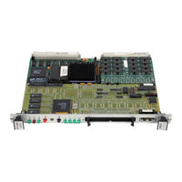
Performance Computer PT-VME141 User Manual (132 pages)
Extensible Single Board Computer/Controller
Brand:
Performance Computer
| Category:
Controller
| Size: 4 MB
Table of Contents
Table of Contents
6
Section 1 INTRODUCTION
16
Scope
16
Applicable Documents
17
System Control Register
17
Model Designations
18
Features
19
Family Members
21
Pt-Vme131/131E
21
Pt-Vme141/141E
22
Pt-Vme151/151E
22
Glossary and Conventions
23
Glossary
23
Conventions
24
Section 2 GETTING STARTED
26
Unpacking and Inspection
26
Hardware Configuration
27
Device Positions
27
Figure 1: PT-VME151A/151AE Device Positions
27
Watchdog" Timer Setup
28
PROM/ROM/SRAM/EEPROM Socket Configuration
29
Figure 2: EPROM/ROM/SRAM/EEPROM Device Orientation
29
Location U23 Setup
30
Location U38 Setup
30
Figure 3: K4 and K10Jumpers
30
Figure 4: K3 and K11 Jumpers
30
Figure 5: U23 and U38 Jumper Settings
31
SCSI Termination
32
Disabling Termination
32
Termination Power Source
32
TERMPWR Overview
32
Figure 6: SCSI Components
32
DRAM Module Upgrading
34
EPAK Installation
35
Board Installation
36
Power Considerations
36
Slot Considerations
36
Backplane Insertion
36
Figure 7: PT-VME151A Front Panel
37
SCSI Considerations
38
Cabling
38
Example
38
Mechanical Restraints
39
SCSI Device Grounds
39
Figure 8: Example SCSI Cable
39
Device Addresses
40
Serial Port Cabling
40
Example
40
Mechanical Restraints
41
Figure 9: Example Serial Port Cable
41
Section 3 FUNCTIONAL DESCRIPTION
42
Figure 10: Block Diagram
42
Microprocessor
43
Memory
43
Dram
43
DRAM Mapping
44
Sizing
44
Parity
45
Checking
45
Initialization
46
Testing
46
PROM/SRAM Sockets
46
Nonvolatile SRAM and Time of Day/Calendar Clock
46
Serial EEPROM
46
Interval Timer
47
Figure 11: Interval Timer Block Diagram
47
Vmebus Interface
48
Darf64
48
VME 64 Transfers
48
Transfer Modes
48
Decoupled
49
Atomic
49
Vmebus Control Logic
49
Vmebus Slave Accesses
50
EPAK Access from the Vmebus
50
Vmebus Master Accesses
50
68040 Accesses
50
Read-Modify-Write
51
Dmac
51
Location Monitor
52
Registers
52
Test and Diagnostics
52
Acc
53
Reset
53
Local Bus Timer
53
Watchdog Timer
53
Tick Timer
54
Register Block
54
Interrupt Handler
54
Local Level 7 Sources
54
Abort
55
SCSI Bus Reset
55
AC Fail
55
System Fail
55
General Purpose Local Interrupts
55
Location Monitor FIFO
56
DARF64 VME Event
56
Timer Event
56
Figure 12: Timer Block Diagram
56
Tick
57
Interval
57
I/O Event
57
FAS216 Requests
57
EPAK Requests (-EPIRQ)
57
EPAK Vectored Interrupt Request
58
DUART Interrupt Request (-INTP<5>)
58
Vmebus Interrupts
58
Interrupt Acknowledgment
59
Vmebus Requester
59
System Monitor Functions
59
Reset
59
System Clock Driver
59
Vmebus Arbiter
59
IACK Daisy Chain Driver
60
Bus Timer
60
I/O Utilities
60
System Control Registers
60
System Control Register
60
Vmebus Page Select
61
User Leds
61
SCSI DMA Read/Write Direction
61
EPAK Space Cache Enable
61
Vmebus Space Cache Enable
61
Table 1: EPAK Caching Options
61
System Control Register 2
62
Enable EPAK Access from the Vmebus
62
Enable Parity Error Checking
62
Enable Bad Parity
62
Enable Interval Timer Interrupts
64
Enable Tick Timer Interrupts
64
System Status Registers
65
System Status Register
65
Hex Switch
65
68040 Parity Error
65
SCSI DMA Parity Error
65
DARF Parity Error
65
EPAK Parity Error
66
SCSI Present
66
System Status Register 3
66
DRAM Size
66
Parity Installed
66
Interval Timer Interrupt Pending
66
Duart
67
Utility Serial Ports
67
General Purpose Timer/Counter
67
Parallel Input Port
67
Clear-To-Send
67
Data-Terminal-Ready
67
EPAK General Purpose Input
68
Serial EEPROM Data in
68
Parallel Output Port
68
Request-To-Send
68
Data-Set-Ready
68
EPAK General Purpose Output
68
Serial EEPROM Select
68
Serial EEPROM Control
68
Serial EEPROM Data out
69
SCSI Controller
70
SCSI Bus
70
Register Access
70
DMA Mechanism
71
Interrupts
71
Termination
71
EPAK Interface
73
Section 4 FUNCTIONAL SUMMARY
74
Memory Map
74
Table 2: Memory Map
74
Default Vmebus Slave Addressing
75
Table 3: Default Vmebus A24 Memory Map
75
Table 4: Default Vmebus A32 Memory Map
75
151A System Registers
76
System Control Register 1
76
System Status Register 1
79
System Status Register 2
80
System Status Register 3
81
SCSI Memory Address Register
82
Jumper List (Defaults)
82
Interrupt Control
83
Table 5: Interrupt Request Summary
83
Register Maps
84
Acc
84
Table 6: ACC Register Map
84
Darf64
85
Table 7: DARF64 Registers
85
DS1643 Nonvolatile Timekeeping RAM
86
82C54 Interval Timer
86
Table 8: DS1643 Nonvolatile Timekeeping RAM Registers
86
Table 9: 82C54 Interval Timer Registers
86
EMULEX FAS216 SCSI Controller
87
68681 Duart
87
Table 10: EMULEX FAS216 SCSI Controller Register Map
87
Table 11: Motorola 68681 DUART Register Map
87
Controls and Indicators
88
Rotary Switch
88
Figure 13: PT-VME151A Front Panel Controls and Indicators
88
RUN" Indicator
89
FAULT" Indicator
89
VME" Indicator
89
RESET Switch
89
ABORT Switch
89
User Programmable Leds
89
Section 5 CONNECTOR PINOUTS
90
Utility Serial Port Pin Assignments
90
Table 12: Utility Serial Port Pin Assignments
90
Vmebus Pin Assignments
91
Table 13: Vmebus "P1" Connections
91
Table 14: Vmebus" P2" Connections
92
EPAK Connectors
93
Table 15: EPAK Connections
93
DRAM Module
94
Table 16: EPAK Mounting Standoffs
94
Table 17: DRAM Module Connections
94
Table 18: EPAK Mounting Standoffs
95
Section 6 MECHANICAL and ENVIRONMENTAL
96
Power Requirements
96
Ambient Temperature
96
Humidity
96
Vibration
96
Table 19: Power Requirements
96
Table 20: Ambient Temperature
96
Table 21: Humidity Constraints
96
Mechanical Shock
97
Physical Dimensions
97
Table 22: Physical Dimensions
97
Section 7 APPENDICES
98
Product Warranty
98
Product Return Procedure
99
Installation Notes
100
EEPROM Usage
101
Ptbug
101
Table 23: EEPROM Default Values
102
Renamed Registers
104
New Devices
104
DRAM Sizing
104
Table 24: 151 to 151A Register Map Differences
104
SRAM Access
105
VME151A Differences from VME131/141
106
DARF64 Uses 68040 Mode
106
SCSI Controller Differences
106
Effects of 68040 Vs. 68030
106
Cacheability and Serialization
106
68040 Cache Control Registers
107
68040 Cache Clearing
108
68040 Exception Processing
108
PT-VME151A Control Register Differences
108
Table 25: EPAK Caching
108
AVICS Overview
110
Functional Description
110
BI-Mode
110
Location Monitor
111
Vmebus Master Memory Map
111
Figure 14: DARF Memory Map
112
Master Vmebus Accesses
113
Slave Vmebus Accesses
114
AVICS Application Notes
116
Local Interrupts
116
Example
116
Table 26: Recommended Interrupt Assignments
116
Setting up the Master Bus Memory Map
117
Example
117
Setting up A24/A32 Slave Images on the Bus
117
Example a
118
Example B
119
Generating Vmebus Interrupts
120
Example
120
Receiving Vmebus Interrupts
120
Initiating a DMA Transfer
121
Example
121
Vmebus Address Modifiers
123
Table 27: Vmebus Address Modifiers
123
Section 8 INDEX
124
Section 9 SCHEMATICS
130
Advertisement
Advertisement
Related Products
Performance Computer PT-VME161
Performance Computer PT-VME151A
Performance Computer PT-VME151AE
Performance Computer Categories
Controller
More Performance Computer Manuals
Login
Sign In
OR
Sign in with Facebook
Sign in with Google
Upload manual
Upload from disk
Upload from URL