Nortel BayStack 410-24T Manuals
Manuals and User Guides for Nortel BayStack 410-24T. We have 3 Nortel BayStack 410-24T manuals available for free PDF download: Using Manual, Specifications
Nortel BayStack 410-24T Using Manual (330 pages)
10BASE-T Switch
Table of Contents
-
-
Preface23
-
Audience24
-
Organization24
-
Acronyms26
-
-
-
Description31
-
Security43
-
IEEE 802.1P46
-
-
-
Base Unit61
-
-
-
-
-
-
Connecting Power130
-
Initial Setup135
-
Stack Setup138
-
-
Main Menu146
-
-
Bootp Disabled153
-
Bootp Always154
-
-
-
Port List Syntax176
-
Asymmetric Mode200
-
Symmetric Mode200
-
Port Statistics221
-
-
Reset266
-
Logout272
-
-
Advertisement
Nortel BayStack 410-24T Using Manual (310 pages)
10BASE-T Switch
Table of Contents
-
Preface
23-
Organization24
-
Acronyms26
-
-
Description29
-
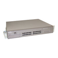
Front Panel30
-
Back Panel34
-
Features37
-
-
Security41
-
IEEE 802.1P44
-
-
-
Base Unit57
-
-
-
-
-
-
Connecting Power126
-
Initial Setup131
-
-
Main Menu142
-
-
Bootp Disabled149
-
Bootp Always150
-
-
-
-
Port Statistics216
-
-
Reset250
-
Logout255
-
Nortel BayStack 410-24T Specifications (8 pages)
Stackable Up to 8 Units and 224 Ports
Advertisement
Advertisement