Sign In
Upload
Manuals
Brands
Nortel Manuals
Switch
BayStack 410 24T
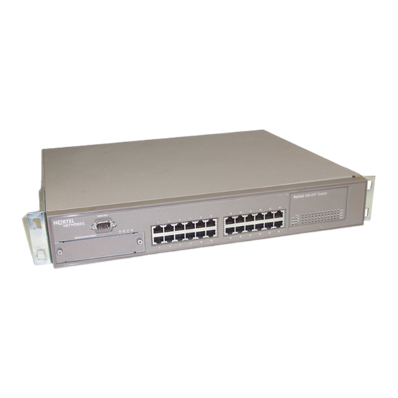
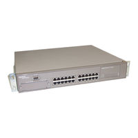
Nortel BayStack 410 24T Manuals
Manuals and User Guides for Nortel BayStack 410 24T. We have
1
Nortel BayStack 410 24T manual available for free PDF download: Using Manual
Nortel BayStack 410 24T Using Manual (310 pages)
10BASE-T Switch
Brand:
Nortel
| Category:
Switch
| Size: 3 MB
Table of Contents
Statement of Conditions
2
Japan/Nippon Requirements Only
3
Table of Contents
7
Preface
23
Before You Begin
24
Organization
24
Text Conventions
25
Acronyms
26
Related Publications
27
How to Get Help
28
Chapter 1 Introduction to the Baystack 410-24T Switch
29
Description
29
Front Panel
30
Comm Port
30
Uplink/Expansion Slot
31
10BASE-T Port Connectors
31
LED Display Panel
32
Baystack 410-24T Switch
32
Back Panel
34
AC Power Receptacle
35
RPSU Connector
36
Cascade Module Slot
36
Cooling Fans
36
Features
37
Virtual Local Area Networks (Vlans)
40
Security
41
RADIUS-Based Network Security
43
MAC Address-Based Security
43
IEEE 802.1P
44
IGMP Snooping Feature
44
Configuration and Switch Management
44
Flash Memory Storage
45
Switch Software Image
45
Configuration Parameters
45
Autosensing and Autonegotiation
46
Multilink Trunking
46
IEEE 802.1Q Vlans
47
Port Mirroring
47
Bootp Automatic IP Configuration/Mac Address
48
SNMP MIB Support
49
SNMP Trap Support
49
Network Configuration
50
Desktop Switch Application
50
Figure 1-6. Baystack 410-24T Switch Used as a Desktop Switch
51
Segment Switch Application
52
High-Density Switched Workgroup Application
53
Figure 1-8. Configuring Power Workgroups and a Shared Media Hub
53
Fail-Safe Stack Application
54
Figure 1-9. Fail-Safe Stack Example
54
Stack Operation
55
Baystack 400-ST1 Cascade Module
55
Cascade a out Connector
56
Unit Select Switch
56
Cascade a in Connector
56
Base Unit
57
Initial Installation
57
Stack MAC Address
58
Temporary Base Unit
58
Removing a Unit from the Stack
59
Stack Configurations
59
Stack up Configurations
60
Stack down Configurations
60
Figure 1-12. Stack up Configuration Example
60
Figure 1-13. Stack down Configuration Example
61
Redundant Cascade Stacking Feature
62
IEEE 802.1Q VLAN Workgroups
64
Figure 1-15. Port-Based VLAN Example
64
IEEE 802.1Q Tagging
65
Vlans Spanning Multiple Switches
69
Vlans Spanning Multiple 802.1Q Tagged Switches
69
Figure 1-21. Vlans Spanning Multiple 802.1Q Tagged Switches
69
Vlans Spanning Multiple Untagged Switches
70
Figure 1-22. Vlans Spanning Multiple Untagged Switches
70
Shared Servers
72
Figure 1-28. Default VLAN Port Configuration Screen Example
76
Figure 1-29. VLAN Port Configuration Screen Example
77
VLAN Workgroup Summary
77
VLAN Configuration Rules
79
IGMP Snooping
80
IGMP Snooping Configuration Rules
84
IEEE 802.1P Prioritizing
85
Figure 1-36. Default Traffic Class Configuration Screen Example
87
Figure 1-37. Setting Port Priority Example
88
Multilink Trunks
89
Client/Server Configuration Using Multilink Trunks
90
Figure 1-39. Switch-To-Server Trunk Configuration Example
90
Trunk Configuration Screen Examples
92
Trunk Configuration Screen for Switch S1
92
Trunk Configuration Screen for Switch S2
95
Figure 1-43. Multilink Trunk Configuration Screen for Switch S2
95
Trunk Configuration Screen for Switch S3
97
Figure 1-44. Multilink Trunk Configuration Screen for Switch S3
97
Trunk Configuration Screen for Switch S4
99
Before Configuring Trunks
101
Multilink Trunking Configuration Rules
101
How the Multilink Trunk Reacts to Losing Distributed Trunk Members
103
Figure 1-1. Baystack 410-24T Switch
103
Spanning Tree Considerations for Multilink Trunks
104
Figure 1-47. Path Cost Arbitration Example
104
Figure 1-48. Example 1: Correctly Configured Trunk
105
Figure 1-49. Example 2: Detecting a Misconfigured Port
106
Additional Tips about the Multilink Trunking Feature
107
Port Mirroring (Conversation Steering)
108
Port-Based Mirroring Configuration
109
Address-Based Mirroring Configuration
111
Figure 1-52. Address-Based Mirroring Configuration Example
112
Port Mirroring Configuration Rules
114
Chapter 2 Installing the Baystack 410-24T Switch
115
Installation Requirements
115
Figure 2-1. Package Contents
116
Installation Procedure
117
Installing the Baystack 410-24T Switch on a Flat Surface
117
Installing the Baystack 410-24T Switch in a Rack
118
Figure 2-2. Positioning the Chassis in the Rack
119
Attaching Devices to the Baystack 410-24T Switch
121
Connecting 10BASE-T Ports and 10/100 MDA Ports
122
Connecting Fiber Optic MDA Ports
123
Console/Comm Port
124
Connecting a Terminal to the Console/Comm Port
125
Connecting Power
126
Verifying the Installation
128
Verifying the Installation Using the Leds
128
Figure 2-10. Observing Leds to Verify Proper Operation
128
Verifying the Installation Using the Self-Test Screen
129
Figure 2-11. Baystack 410-24T Switch Self-Test Screen
129
Figure 2-12. Nortel Networks Logo Screen
130
Initial Setup
131
Standalone Switch Setup
131
Figure 2-13. Main Menu
132
Stack Setup
134
Figure 2-15. Main Menu (Standalone Switch Example)
135
Figure 2-16. Main Menu (Stack Configuration Example)
135
Chapter 3 Using the Console Interface
139
Accessing the CI Menus and Screens
139
Using the CI Menus and Screens
140
Navigating the CI Menus and Screens
140
Screen Fields and Descriptions
141
Main Menu
142
Figure 3-2. Console Interface Main Menu
142
IP Configuration/Setup
146
Choosing a Bootp Request Mode
148
Bootp Disabled
149
Bootp or Last Address
149
Bootp When Needed
150
Bootp Always
150
SNMP Configuration
151
SNMP Configuration Screen Fields
151
System Characteristics
153
System Characteristics Screen
153
Switch Configuration
156
Figure 3-6. Switch Configuration Menu Screen
156
MAC Address Table
158
MAC Address-Based Security
160
Figure 3-8. MAC Address Security Configuration Menu
161
MAC Address Security Configuration
162
Figure 3-9. MAC Address Security Configuration Screen
163
Figure 3-10. MAC Address Security Port Configuration (Screen 1 of 2)
166
MAC Address Security Port Configuration
166
Figure 3-11. Mac Address Security Port Configuration (Screen 2 Of)
167
Figure 3-12. Mac Address Security Port Lists Screens (5 Screens)
169
MAC Address Security Port Lists
169
Figure 3-13. Mac Address Security Port Lists Screen
170
MAC Address Security Port Lists Screen Fields
170
MAC Address Security Table
173
Figure 3-15. Mac Address Security Table Screen
174
VLAN Configuration Menu
176
VLAN Configuration
178
Figure 3-17. Vlan Configuration Screen
179
VLAN Port Configuration
184
VLAN Display by Port
187
Traffic Class Configuration
188
Figure 3-20. Traffic Class Configuration Screen
189
Figure 3-21. Port Configuration Screen (1 of 2)
190
Port Configuration
190
Figure 3-22. Port Configuration Screen (2 of 2)
191
High Speed Flow Control Configuration
192
Choosing a High Speed Flow Control Mode
194
Symmetric Mode
194
Multilink Trunk Configuration
195
Multilink Trunk Configuration Screen
197
Figure 3-25. Multilink Trunk Configuration Screen
198
Multilink Trunk Utilization Screen
199
Figure 3-26. Multilink Trunk Utilization Screen (1 Of)
200
Port Mirroring Configuration
202
Figure 3-28. Port Mirroring Configuration Screen
203
Figure 3-29. Rate Limiting Configuration Screen (1 of 2)
206
Rate Limiting Configuration
206
Figure 3-30. Rate Limiting Configuration Screen (2 of 2)
207
IGMP Configuration Menu
209
IGMP Configuration
210
Multicast Group Membership
214
Port Statistics
216
Console/Comm Port Configuration
220
Figure 3-35. Console/Comm Port Configuration Screen
220
Table 3-31. Console/Comm Port Configuration Screen Fields
220
Renumber Stack Units
227
Hardware Unit Information
229
Spanning Tree Configuration
229
Spanning Tree Port Configuration
230
Figure 3-39. Spanning Tree Port Configuration Screen (1 of 2)
231
Figure 3-40. Spanning Tree Port Configuration Screen (2 of 2)
232
Table 3-34. Spanning Tree Port Configuration Screen Fields
232
Display Spanning Tree Switch Settings
234
Figure 3-41. Spanning Tree Switch Settings Screen
234
TELNET Configuration
237
Software Download
240
Figure 3-43. Software Download Screen
241
Table 3-37. Software Download Screen Fields
241
LED Indications During the Download Process
242
Table 3-38. LED Indications During the Software Download Process
243
Configuration File
244
Figure 3-44. Configuration File Download/Upload Screen
244
Table 3-40. Parameters Not Saved to the Configuration File
246
Display Event Log
247
Figure 3-45. Event Log Screen
247
Excessive Bad Entries
248
Write Threshold
248
Flash Update
249
Reset
250
Figure 3-49. Self-Test Screen after Resetting the Switch
250
Figure 3-50. Nortel Networks Logo Screen
251
Reset to Default Settings
252
Figure 3-51. Self-Test Screen after Resetting to Default Settings
253
Figure 3-52. Nortel Networks Logo Screen after Resetting to Default Settings
254
Logout
255
Chapter 4 Troubleshooting
257
Interpreting the Leds
258
Table 4-1. Baystack 410-24T Switch LED Descriptions
259
Diagnosing and Correcting the Problem
260
Normal Power-Up Sequence
261
Table 4-2. Corrective Actions
261
Port Connection Problems
262
Autonegotiation Modes
263
Port Interface
263
Software Download Error Codes
264
Table 4-3. Software Download Error Codes
264
Appendix A Technical Specifications
267
Environmental
267
Electrical
267
Physical Dimensions
268
Performance Specifications
268
Network Protocol and Standards Compatibility
268
Data Rate
269
Interface Options
269
Safety Agency Certification
269
Electromagnetic Emissions
269
Electromagnetic Immunity
270
Declaration of Conformity
270
Appendix B Media Dependent Adapters
271
10Base-T/100Base-Tx Mda
272
Figure B-1. 400-4TX MDA Front Panel
272
Table B-1. 400-4TX MDA Components
272
100BASE-FX Mdas
273
Table B-2. 100BASE-FX MDA Components
275
Installing an MDA
276
Figure B-3. Installing an MDA
276
Replacing an MDA with a Different Model
277
Appendix C Quick Steps to Features
279
Configuring 802.1Q Vlans
280
Figure C-2. Configuring 802.1Q Vlans (2
281
Configuring Multilink Trunks
283
Configuring Port Mirroring
284
Figure C-5. Configuring Port Mirroring (1
284
Configuring IGMP Snooping
286
Configuring IGMP Snooping (2 of 3)
287
Configuring IGMP Snooping (3 of 3)
288
Appendix D Connectors and Pin Assignments
289
RJ-45 (10BASE-T/100BASE-TX) Port Connectors
289
MDI and MDI-X Devices
290
MDI-X to MDI Cable Connections
291
MDI-X to MDI-X Cable Connections
292
DB-9 (RS-232-D) Console/Comm Port Connector
293
Appendix E Default Settings
295
Appendix F Sample Bootp Configuration File
303
Advertisement
Advertisement
Related Products
Nortel BayStack 410-24T
Nortel 4050
Nortel 4548GT
Nortel BayStack 470-48T-PWR
Nortel 450 series
Nortel 4548GT-PWR
Nortel 4526GTX-PWR
Nortel Passport 4450ac
Nortel BayStack 450 10 Series
Nortel 4526T-PWR
Nortel Categories
IP Phone
Telephone
Switch
Software
Server
More Nortel Manuals
Login
Sign In
OR
Sign in with Facebook
Sign in with Google
Upload manual
Upload from disk
Upload from URL