Sign In
Upload
Manuals
Brands
Maple Armor Manuals
Control Panel
FW106C
Maple Armor FW106C Manuals
Manuals and User Guides for Maple Armor FW106C. We have
1
Maple Armor FW106C manual available for free PDF download: Installation And Operation Manual
Maple Armor FW106C Installation And Operation Manual (73 pages)
Fire Alarm Control Panel
Brand:
Maple Armor
| Category:
Control Panel
| Size: 1 MB
Table of Contents
Table of Contents
2
Control Panel Limitations
7
Agency Listings, Approvals
8
Underwriters Laboratories (UL/ULC)
8
Requirements for All Installations
8
Requirements for Local Protected Fire Alarm Systems
8
Overview
9
Fw106/Fw106Cfire Alarm Control Panel
9
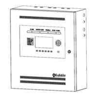
Figure 1 FW106/FW106C Control Panel
9
Board Assembly Diagram
11
Figure 2 Assembly Diagram
11
Figure 3 Assembly Diagram (Inside)
11
FW106/FW106C Configuration
12
Table 1 FW106/FW106C Module Units
12
Specifications and Features
13
Table 2 FW106/FW106C Control Panel Specifications
13
System Components
14
Components Overview
14
Table 3 System Components
14
Ami
15
Figure 4 AMI (Front)
15
Ptu
16
Figure 5 AMI (Back)
16
Figure 6 PTU
16
Pcu
17
Figure 7 PCU
17
Alu
18
Nou
19
Rou
20
Xnu
21
Battery
21
Figure 11 XNU
21
Installation
22
Cautions
22
Control Panel Location
22
Control Panel Installation Notice
22
FW106/FW106C Mounting Space
23
Figure 12 FW106/FW106C Enclosure Mounting Size
23
FW106/FW106C Installation Size
24
Figure 13 FW106/FW106C Installation Size
24
Cabinet Mounting
25
Remove Knock-Outs
25
Figure 14 Wiring Separation
26
Battery Installation
27
Figure 15 Battery Installation
27
Table 4 Battery Space
27
Unit Address Setting
28
Figure 8 ALU
28
Figure 9 NOU
28
Figure 10 ROU
28
Figure 16 Unit Address Switch
28
Table 5 Unit Address Range
28
System Wiring
29
Wiring Notes
29
Power Limiting
29
Wiring Entering the Enclosure
29
Wiring Separation
30
Power Supply Wiring
30
AC Connection
30
Figure 17 Wiring Terminals Location
30
Figure 18 AC Power Supply Wiring
31
Figure 19 Ground Wiring
31
Figure 20 AC Power Supply Wiring (Terminal)
32
Battery Connection
33
Figure 21 Battery Connection
33
Addressable Loop Circuit Wiring
34
Addressable Loop Circuit Wiring - Class
34
Figure 22 Addressable Loop Circuit Wiring - Class
34
Figure 23 Addressable Loop Circuit Wiring - Class
35
Notification Appliance Circuit Wiring
36
Notification Appliance Circuit Wiring - Class
36
Figure 24 Notification Appliance Circuit Wiring - Class
36
Figure 25 Notification Appliance Circuit Wiring - Class
37
Relay Output Circuit Wiring
38
Figure 26 Relay Output Circuit Wiring
38
External Network Circuit Wiring
39
External Network Circuit Wiring - Class
39
Figure 27 External Network Circuit Wiring - Class
39
Auxiliary Power Output Wiring
40
Communication Port Connection
40
Figure 28 Auxiliary Power Output Wiring
40
Figure 29 AMI
41
System Checkout
42
Before Turning the Power
42
Power-Up Procedure
42
Troubleshooting
43
Circuit Trouble
43
Ground Fault
43
Battery Trouble
43
Common Trouble
43
Table 6 Circuit Trouble
43
Operation
44
Status Handling
44
Standby Condition
44
Alarm Conditions
44
Figure 30 LCD (Standby)
44
Trouble Conditions
45
Figure 31 LCD (Trouble)
45
Table 7 Trouble Event Type
46
Supervisory Conditions
47
Device, Appliance Handling
48
NAC Activation and Silence
48
Device Supervision
48
Detector Monitor
48
Manual Station Response
49
Drift Compensation
49
Alarm Verification
49
Figure 32 Alarm Verification
49
Positive Alarm Sequence (PAS)
50
Figure 33 Positive Alarm Sequence
50
Two-Stage
51
By-Pass
51
Auto Addressing
51
Figure 34 Two-Stage Alarm
51
Event History
52
LED, Buzzer, Buttons
53
Leds Operation
53
Table 8 Leds Operation
53
Buzzer Operation
54
Button Operation
55
Table 9 Buttons Function
55
LCD Display
56
Lamp Test
56
Configuration and Maintenance
57
PC Configuration
57
Control Panel Access Control
57
Control Panel Configuration
58
Table 10 Access Level 0 Operation
58
Table 11 Access Level 1 Operation
58
Table 12 Access Level 2 Operation
58
Table 13 Access Level 3 Operation
59
Appendix-A: Compatible Devices
63
Devices for Addressable Loop Circuits
63
Appliances for Notification Appliance Circuits
63
Table 14 Device for Addressable Device Circuits
63
Table 15 Appliance for Notification Appliance Circuits
63
Appendix-B: Wire Selection Guide
64
SLC Wire Selection Guide
64
Table 16 Addressable Loop Wiring
64
NAC Wire Selection Guide
65
Annunciator Wire Selection Guide
65
Table 17 NAC Wiring Table
65
Table 18 Annunciator Wiring Table
65
Appendix-C: Quantities of Notification Appliances
66
Table 19 Maximum Numbers of
66
Appendix-D: Battery Calculations
67
Total System Currents Calculations
67
Table 20 System Currents Calculation
67
Battery Capacity
69
Table 21 Battery Calculation
69
Appendix-E: Glossary and Acronyms
70
Advertisement
Advertisement
Related Products
Maple Armor FW106S,FW106SC
Maple Armor FW106
Maple Armor FW105
Maple Armor FW131
Maple Armor FW6308-CLA1
Maple Armor Categories
Control Unit
Control Panel
Security Sensors
Monitor
Intercom System
More Maple Armor Manuals
Login
Sign In
OR
Sign in with Facebook
Sign in with Google
Upload manual
Upload from disk
Upload from URL