
Related Manuals for Maple Armor FW106


Summary of Contents for Maple Armor FW106
- Page 1 Maple Armor FW106, FW106C Fire Alarm Control Panel Installation and Operation Manual DOC‐FW106‐UM‐R1.6 ...
-
Page 2: Table Of Contents
Control Panel Limitations .............................. 1 Agency Listings, Approvals .............................. 2 Underwriters Laboratories (UL/ULC) .......................... 2 Requirements for All Installations ........................ 2 Requirements for Local Protected Fire Alarm Systems .................. 2 Overview .................................... 3 FW106/FW106CFire Alarm Control Panel ........................ 3 Board Assembly Diagram ............................ 5 FW106/FW106C Configuration .......................... 6 Specifications and Features ............................ 7 System Components .............................. 8 Components Overview ............................ 8 ... - Page 3 Installation and Operation Manual ...
- Page 4 Installation and Operation Manual ...
- Page 5 Installation and Operation Manual List of Figures Figure 1 FW106/FW106C Control Panel .......................... 3 Figure 2 Assembly Diagram .............................. 5 Figure 3 Assembly Diagram (Inside) ........................... 5 ...
- Page 6 Installation and Operation Manual List of Tables Table 1 FW106/FW106C Module Units .......................... 6 Table 2 FW106/FW106C Control Panel Specifications ....................... 7 Table 3 System Components .............................. 8 ...
-
Page 7: Control Panel Limitations
Installation and Operation Manual Control Panel Limitations The FW106/FW106C control panel may not show an alarm condition without compatible initiating devices (smoke detectors, etc.) and notification devices (horn, lights, etc.) connected to it. Electrical ratings of the initiation and notification appliances must be compatible with the electrical ratings of the control panel ... -
Page 8: Agency Listings, Approvals
Installation and Operation Manual Agency Listings, Approvals Underwriters Laboratories (UL/ULC) Requirements for All Installations The general requirements are described in this section. When installing an individual device, refer to the specific section of the manual for additional requirements. 1. All field wiring must be installed in accordance with NFPA 70 National Electric Code, CSA C22.1 Canadian Electrical Code Part 1, CAN/ULC‐S524, NBC, NBC, NFC, AHJ, and local code requirements. 2. Use the addressable smoke detectors listed in the compatibility chart (Appendix‐A: Compatible Devices). 3. Use UL/ULC listed notification appliances compatible with the FW106/FW106C from those specified in Appendix‐A: Compatible Devices of this manual. 4. A full system verification must be performed every time the panel is programmed or reprogrammed. Requirements for Local Protected Fire Alarm Systems At least one UL listed supervised notification appliances must be used. 2 ... -
Page 9: Overview
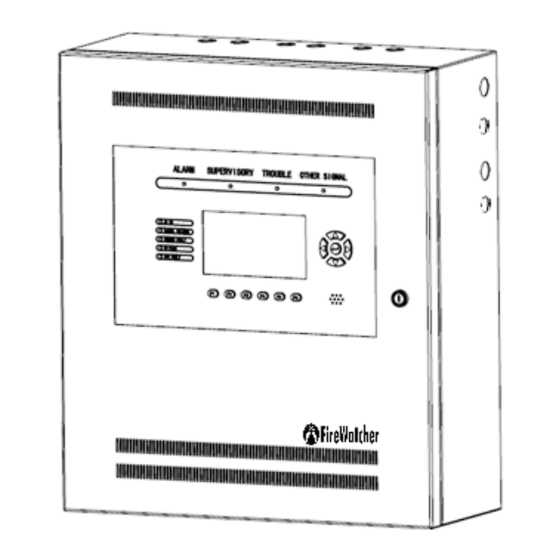
FW106/FW106CFire Alarm Control Panel The FireWatcher FW106/FW106C is an intelligent Fire Alarm Control Panel designed for small to medium‐scale facilities. The FireWatcher FW106/FW106C is ideally suited for both new and retrofit commercial, institutional, and industrial fire detection and notification applications. The only difference between FW106 and FW106C is the language. FW106 is in English and FW106C is in French. (a) FW106 (English) (b) FW106C (French) Figure 1 FW106/FW106C Control Panel The FireWatcher FW106/FW106C is an addressable fire control system that meets the requirements of UL 864 Edition, and CAN/ULC‐S527 3 edition. It can support: 4 Addressable Loop Circuits and 1,008 addressable devices/points ... - Page 10 Installation and Operation Manual The FW106/FW106C can also connect with up to 110 panels and/or remote annunciators via a CAN bus to form a fire emergency detection and notification network system. ...
-
Page 11: Board Assembly Diagram
Installation and Operation Manual Board Assembly Diagram The FW106/FW106C provides modular assemble style. Figure 2 and Figure 3 show the assembly diagram: Figure 2 Assembly Diagram ... -
Page 12: Fw106/Fw106C Configuration
Installation and Operation Manual FW106/FW106C Configuration The FW106/FW106C function is governed by several modules. All the functional module units are shown in Table 1: ... -
Page 13: Specifications And Features
Installation and Operation Manual Specifications and Features The specifications and features of the FW106/FW106C Control Panel are described in Table 2. Table 2 FW106/FW106C Control Panel Specifications General Digital signal processor based design, fully configurable from front panel with ... -
Page 14: System Components
Circuits Class A/Class B circuit 252 addresses: detectors and modules max Output voltage range: 20.2V ~ 26.2V Maximum normal standby current: 100mA Maximum alarm current: 220mA Max. line capacitance = 0.1 uF Max. line resistance = 10 Ohm System Components Components Overview Table 3 describes the FW106/FW106Ccomponents. Table 3 System Components Model Description FW106/FW106C Components FW201/FW201C AMI(Advanced Machine Interface) √ FW391 PTU(Power‐supply Transformer Unit) √ FW397 PCU (Power‐supply and Charger Unit) √ FW327 ALU (Addressable Loop Unit) √ FW337 NOU (Notification Output Unit) √ ... -
Page 15: Ami
Installation and Operation Manual AMI The AMI is the main control unit of FW106/FW106C panel, which integrates the CPU board, 4 Signal status LEDs, 5 system status LEDs, 4 navigation buttons and 1 enter button, 6 functionality buttons and a buzzer. ... -
Page 16: Ptu
Installation and Operation Manual ... -
Page 17: Pcu
Installation and Operation Manual ... -
Page 18: Alu
Installation and Operation Manual ... -
Page 19: Nou
Installation and Operation Manual ... -
Page 20: Rou
Installation and Operation Manual ... -
Page 21: Xnu
Installation and Operation Manual XNU TheFW106/FW106C control panel communicates to panels/annunciators, up to 110 nodes on a network. Circuit topology support: Class B. XNU address is set by configuration from the panel or configurator. The valid address range of the FW106/FW106C or a compatible annunciator is 1 to 110. Figure 11 XNU The XNU must be set to a correct address before use. Please refer to Unit Address Setting section for detail. ... -
Page 22: Installation
Installation and Operation Manual ... -
Page 23: Fw106/Fw106C Mounting Space
Installation and Operation Manual FW106/FW106C Mounting Space The FW106/FW106C cabinet can be surface‐mounted or flush‐mounted. ... -
Page 24: Fw106/Fw106C Installation Size
Installation and Operation Manual FW106/FW106C Installation Size ... -
Page 25: Cabinet Mounting
Installation and Operation Manual ... -
Page 26: Figure 14 Wiring Separation
Installation and Operation Manual ... -
Page 27: Battery Installation
Installation and Operation Manual ... -
Page 28: Unit Address Setting
Installation and Operation Manual Unit Address Setting Units (ALU, NOU, ROU, PCU) have an internal rotary switch to set an address. The rotary switch is located at the bottom of each unit’s cover. Figure 16 Unit Address Switch XNU’s address should be programmed on the panel’s attribute screen (Refer to Programming Manual DOC‐FW106‐PM for details) The unit must be set to an appropriate address before use. The valid address range is listed in Table 5. Table 5 Unit Address Range Unit Type Address Range ALU 1~4 ... -
Page 29: System Wiring
Electric light Power Class 1 or non‐power limited fire protective signaling conductors To meet these requirements, the following guidelines must be observed when installing modules and wiring to this control panel. When installing power limited field wiring, the installer must comply with NEC article 760, which states: The fire alarm power‐limited circuits are installed using Types FPL, FPLR, FPLP or permitted substitute cable, provided these power‐limited cable conductors extending beyond the jacket are separated by a minimum of 0.25 in. (6.35 mm) or by a nonconductive sleeve or nonconductive barrier from all other conductors. If energy limited cable or equivalent is not used within the FW106/FW106C enclosure, then the following guidelines do not apply. In that case, be sure to follow standard wiring practices. Wiring Entering the Enclosure Non‐Power Limited Wiring ‐ Wiring entering the enclosure from the bottom left side and right side of the enclosure is considered non‐power limited wiring. Wiring must be in the shortest route and must not overlap any other wiring. Power Limited Wiring ‐ Wiring entering the enclosure from the upper left side of the enclosure or the right ... -
Page 30: Wiring Separation
Installation and Operation Manual ... -
Page 31: Figure 18 Ac Power Supply Wiring
Installation and Operation Manual ... -
Page 32: Figure 20 Ac Power Supply Wiring (Terminal)
Installation and Operation Manual ... -
Page 33: Battery Connection
Installation and Operation Manual ... -
Page 34: Addressable Loop Circuit Wiring
Installation and Operation Manual ... -
Page 35: Figure 23 Addressable Loop Circuit Wiring - Class
Installation and Operation Manual ... -
Page 36: Notification Appliance Circuit Wiring
Installation and Operation Manual ... -
Page 37: Figure 25 Notification Appliance Circuit Wiring - Class
Installation and Operation Manual ... -
Page 38: Relay Output Circuit Wiring
Installation and Operation Manual ... -
Page 39: External Network Circuit Wiring
Installation and Operation Manual External Network Circuit Wiring External network circuit can address up to 110 panels and/or remote annunciators. FW106/FW106C control panel can connect to panels/annunciators by using External Network Unit. Remote Device Power – The control panel auxiliary power can provide power for 4 annunciators. Each address on the circuit must be fully powered from either auxiliary power of control panel UL/ULC Listed power supply ... -
Page 40: Auxiliary Power Output Wiring
Installation and Operation Manual ... -
Page 41: Figure 29 Ami
Installation and Operation Manual ... -
Page 42: System Checkout
Installation and Operation Manual System Checkout The following are the recommended steps that should be followed before and during the powering up of the FW106/FW106C. Before Turning the Power ON 1. To prevent sparking, DO NOT connect the battery first. Connecting the batteries should only be done once the system has been powered from the main AC Supply. ... -
Page 43: Troubleshooting
Installation and Operation Manual ... -
Page 44: Operation
Installation and Operation Manual ... -
Page 45: Trouble Conditions
Installation and Operation Manual ... -
Page 46: Table 7 Trouble Event Type
Installation and Operation Manual ... -
Page 47: Supervisory Conditions
Installation and Operation Manual ... -
Page 48: Device, Appliance Handling
Installation and Operation Manual ... -
Page 49: Manual Station Response
Installation and Operation Manual ... -
Page 50: Positive Alarm Sequence (Pas)
Installation and Operation Manual ... -
Page 51: Two-Stage
Installation and Operation Manual ... -
Page 52: Event History
Installation and Operation Manual ... -
Page 53: Led, Buzzer, Buttons
Installation and Operation Manual LED, Buzzer, Buttons The FW106/FW106C has a buzzer, 9 LEDs, 5 navigational buttons and enter button, 6functionality buttons. LEDs Operation Refer to Table 8 for the LEDs operation. ... -
Page 54: Buzzer Operation
Installation and Operation Manual ... -
Page 55: Button Operation
Installation and Operation Manual ... -
Page 56: Lcd Display
Installation and Operation Manual ... -
Page 57: Configuration And Maintenance
Installation and Operation Manual Configuration and Maintenance PC Configuration Programming the panel may be done by temporarily connecting the programming port to a computer. This is the recommended method to configure the panel. The Maple Armor FW401 Configurator software is available to configure of the control panel using a Personal Computer (PC) with an Ethernet port. This allows ease of operation by preparing the program in advance and downloading it to the control panel by a simple and fast operation. Control Panel Access Control The FW106/FW106C provides configuration and maintenance functions to set and control various features in the system. The configuration and maintenance functions are protected by access control. The following levels of security protect the system from unauthorized use: Level 1 – Locked Door Level 2 – Locked Door and 4‐digit Password, Level 2 provides control functions. Level 3 – Locked Door and 4‐digit Password, Level 3 provides control functions and parameter change ... -
Page 58: Control Panel Configuration
Installation and Operation Manual ... -
Page 59: Table 13 Access Level 3 Operation
Installation and Operation Manual ... - Page 60 Installation and Operation Manual ...
- Page 61 Installation and Operation Manual ...
- Page 62 Installation and Operation Manual ...
-
Page 63: Appendix-A: Compatible Devices
Installation and Operation Manual ... -
Page 64: Appendix-B: Wire Selection Guide
Installation and Operation Manual ... -
Page 65: Nac Wire Selection Guide
Installation and Operation Manual ... -
Page 66: Appendix-C: Quantities Of Notification Appliances
Installation and Operation Manual ... -
Page 67: Appendix-D: Battery Calculations
Installation and Operation Manual ... - Page 68 Installation and Operation Manual ...
-
Page 69: Battery Capacity
Installation and Operation Manual ... -
Page 70: Appendix-E: Glossary And Acronyms
Installation and Operation Manual ... - Page 71 Installation and Operation Manual ...
- Page 72 Installation and Operation Manual ...
- Page 73 Maple Armor © 2019 MAPLE ARMOR FIRE ALARM DEVICE CO., LTD. ...
Need help?
Do you have a question about the FW106 and is the answer not in the manual?
Questions and answers