Sign In
Upload
Manuals
Brands
Emerson Manuals
Transmitter
Micro Motion
Emerson Micro Motion Manuals
Manuals and User Guides for Emerson Micro Motion. We have
8
Emerson Micro Motion manuals available for free PDF download: Configuration And Use Manual, User Manual, Installation Manual, Quick Start Manual
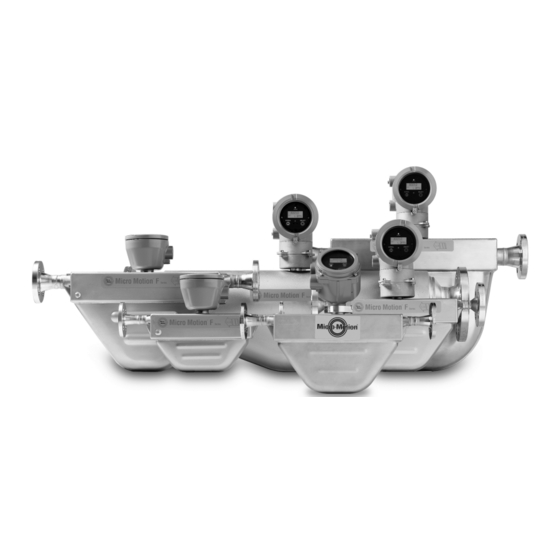
Emerson Micro Motion Configuration And Use Manual (212 pages)
Fork Density Meters
Brand:
Emerson
| Category:
Measuring Instruments
| Size: 2.81 MB
Table of Contents
Table of Contents
3
Getting Started
7
Chapter 1 Before You Begin
9
About this Manual
9
Model Codes and Device Types
9
Communications Tools and Protocols
10
Additional Documentation and Resources
11
Chapter 2 Quick Start
13
Power up the Transmitter
13
Check Meter Status
13
Make a Startup Connection to the Transmitter
14
Part II Configuration and Commissioning
17
Chapter 3 Introduction to Configuration and Commissioning
19
Default Values
19
Enable Access to the Off-Line Menu of the Display
19
Disable HART Security
19
Set the HART Lock
22
Restore the Factory Configuration
22
Chapter 4 Configure Process Measurement
25
Verify the Calibration Factors
25
Calibration Factors
26
Configure Line Density Measurement
26
Configure Density Measurement Unit
26
Configure Density Damping
28
Configure Density Cutoff
29
Configure Two-Phase Flow Parameters
30
Configure Temperature Measurement
31
Configure Temperature Measurement Unit
31
Configure Temperature Damping
32
Configure Temperature Input
33
Configure the Pressure Input
37
Configure the Pressure Input Using Prolink III
37
Configure the Pressure Input Using the Field Communicator
38
Options for Pressure Measurement Unit
39
Set up the API Referral Application
40
Set up the API Referral Application Using Prolink III
40
Set up the API Referral Application Using the Field Communicator
46
Set up Concentration Measurement
52
Preparing to Set up Concentration Measurement
52
Set up Concentration Measurement Using Prolink III
53
Set Reference Temperature Values for Specific Gravity Using Prolink
55
Set up Temperature Data for Concentration Measurement Using Prolink
56
Modify Matrix Names and Labels Using Prolink III
58
Modify Operational Parameters for Concentration Measurement Using Prolink
58
Set up Concentration Measurement Using the Field Communicator
60
Select the Active Concentration Matrix Using Prolink III
60
Enable the Concentration Measurement Application Using
61
Using Equations to Calculate Specific Gravity, °Baumé, °Brix, °Plato, and °Twaddell
65
Matrix Switching
66
Measuring Net Mass Flow Rate and Net Volume Flow Rate
68
Set up Flow Rate Measurement
68
Set up Flow Rate Measurement Using Prolink III
68
Set up Flow Rate Measurement Using the Field Communicator
70
Chapter 5 Configure Device Options and Preferences
73
Configure the Transmitter Display
73
Configure the Language Used for the Display
73
Configure the Process Variables and Diagnostic Variables Shown on the Display
74
Configure the Number of Decimal Places (Precision) Shown on the Display
74
Configure the Refresh Rate of Data Shown on the Display
75
Enable or Disable Automatic Scrolling through the Display Variables
75
Enable or Disable Operator Actions from the Display
76
Enable or Disable the Acknowledge All Alerts Display Command
76
Configure Security for the Display Menus
77
Configure Alert Handling
78
Configure Fault Timeout
78
Configure Status Alert Severity
79
Configure Informational Parameters
81
Chapter 6 Integrate the Meter with the Control System
83
Configure Channel B
83
Configure the Ma Output
84
Configure Ma Output Process Variable
84
Prolink III
85
Configure Lower Range Value (LRV) and Upper Range Value (URV)
86
Configure Added Damping
87
Configure Ma Output Fault Action and Ma Output Fault Level
88
Configure the Discrete Output
90
Configure Discrete Output Source
90
Configure Discrete Output Polarity
91
Configure Discrete Output Fault Action
92
Configure an Enhanced Event
93
Configure Hart/Bell 202 Communications
94
Configure Basic HART Parameters
94
Configure HART Variables (PV, SV, TV, QV)
95
Configure Burst Communications
97
Configure Modbus Communications
101
Configure Digital Communications Fault Action
102
Options for Digital Communications Fault Action
103
Chapter 7 Completing the Configuration
105
Test or Tune the System Using Sensor Simulation
105
Back up Transmitter Configuration
105
Enable HART Security
106
Part III Operations, Maintenance, and Troubleshooting
109
Chapter 8 Transmitter Operation
111
Record the Process Variables
111
View Process Variables
111
View Process Variables Using the Display
111
View Process Variables and Other Data Using Prolink III
112
View Process Variables Using the Field Communicator
112
View and Acknowledge Status Alerts
113
View and Acknowledge Alerts Using the Display
113
View and Acknowledge Alerts Using Prolink III
115
View Alerts Using the Field Communicator
116
Alert Data in Transmitter Memory
116
Chapter 9 Measurement Support
119
Perform the Known Density Verification Procedure
119
Perform the Known Density Verification Procedure Using the Display
119
Perform the Known Density Verification Procedure Using Prolink III
120
Perform the Known Density Verification Procedure Using the Field Communicator
121
Adjust Density Measurement with Density Offset or Density Meter Factor
122
Perform Density Offset Calibration
124
Perform Density Offset Calibration Using the Display
124
Perform Density Offset Calibration Using Prolink III
125
Perform Density Offset Calibration Using the Field Communicator
126
Adjust Temperature Measurement with Temperature Offset or Temperature Slope
127
Perform Temperature Calibration
128
Perform Temperature Calibration Using the Display
129
Perform Temperature Calibration Using Prolink III
130
Perform Temperature Calibration Using the Field Communicator
130
Adjust Concentration Measurement with Trim Offset
132
Adjust Concentration Measurement with Trim Offset and Trim Slope
133
Set up User-Defined Calculations
135
Equations Used in User-Defined Calculations
137
Measurement Units Used in User-Defined Calculations
137
Chapter 10 Troubleshooting
139
Quick Guide to Troubleshooting
139
Check Power Supply Wiring
140
Check Grounding
141
Perform Loop Tests
141
Perform Loop Tests Using the Display
142
Perform Loop Tests Using Prolink III
143
Perform Loop Tests Using the Field Communicator
144
Status LED States
146
Status Alerts, Causes, and Recommendations
147
Density Measurement Problems
152
Temperature Measurement Problems
153
API Referral Problems
154
Concentration Measurement Problems
154
Milliamp Output Problems
155
Discrete Output Problems
157
Time Period Signal (TPS) Output Problems
157
Using Sensor Simulation for Troubleshooting
157
Trim Ma Outputs
158
Trim Ma Outputs Using Prolink III
158
Trim Ma Outputs Using the Field Communicator
159
Check HART Communications
159
Check Lower Range Value and Upper Range Value
161
Check Ma Output Fault Action
161
Check for Radio Frequency Interference (RFI)
161
Check the Cutoffs
162
Check for Two-Phase Flow (Slug Flow)
162
Check the Drive Gain
163
Collect Drive Gain Data
164
Check the Pickoff Voltage
164
Collect Pickoff Voltage Data
164
Check for Internal Electrical Problems
165
Locate a Device Using the HART 7 Squawk Feature
165
Appendix A Calibration Certificate
167
Sample Calibration Certificate
167
Appendix B Using the Transmitter Display
169
Components of the Transmitter Interface
169
Use the Optical Switches
169
Access and Use the Display Menu System
170
Enter a Floating-Point Value Using the Display
171
Display Codes for Process Variables
174
Codes and Abbreviations Used in Display Menus
175
Appendix C Using Prolink III with the Transmitter
187
Basic Information about Prolink III
187
Connect with Prolink III
188
Connection Types Supported by Prolink III
188
Connect with Prolink III over Modbus/Rs-485
189
Connect with Prolink III over Hart/Bell 202
192
Appendix D Using the Field Communicator with the Transmitter
201
Basic Information about the Field Communicator
201
Connect with the Field Communicator
202
Appendix E Concentration Measurement Matrices, Derived Variables, and Process Variables
205
Standard Matrices for the Concentration Measurement Application
205
Concentration Measurement Matrices Available by Order
206
Derived Variables and Calculated Process Variables
208
Advertisement
Emerson Micro Motion Installation Manual (74 pages)
Model D and DT Sensors
Brand:
Emerson
| Category:
Transmitter
| Size: 2.55 MB
Table of Contents
Table of Contents
3
Before You Begin
5
Your New Sensor
5
The Installation Process
10
Additional Information
11
Step 2. Location
13
Pipe Run
13
Maximum Wiring Distances
13
DT Sensor Junction Box
14
Environmental Limits
14
Valves
14
Hazardous Area Installations
15
Step 3. Orientation
17
Flow Direction
17
Process Fluid
17
Step 4. Mounting
21
Conduit Openings
22
Optional Model D600 Mounting
22
DT Sensors
22
Step 5. Wiring
23
Hazardous Area Installations
23
Model D Sensor Junction Box
23
Model DT Sensor Cable and Junction Box
24
Connecting and Shielding 9-Wire Cable
25
D600 Sensor
29
Power Supply Wiring to the Remote Booster Amplifier
30
Power Supply Wiring to the Integral Booster Amplifier
31
Wiring from the Remote Booster Amplifier to the Sensor
32
Wiring to a Transmitter (D600 Sensor with Junction Box)
33
Core Processor to a 4-Wire Remote Transmitter or Remote Host
36
Sensor Grounding
41
Step 6. Startup
43
Zeroing
43
Configuration, Calibration, and Characterization
43
Customer Service
44
Troubleshooting
45
General Information
45
Zero Drift
46
Erratic Flow Rate
47
Inaccurate Flow Rate or Batch Total
48
Inaccurate Density Reading
49
Inaccurate Temperature Reading
50
Troubleshooting at the Transmitter
50
Troubleshooting at the Sensor
55
Purge Fittings
59
Appendix A Purge Fittings
63
Rupture Disk
63
Appendix B Rupture Disk
65
Label Maintenance and Replacement
65
Appendix C Label Maintenance and
69
Return Policy
69
Emerson Micro Motion User Manual (76 pages)
EtherNet/IP Module
Brand:
Emerson
| Category:
Control Unit
| Size: 1.12 MB
Table of Contents
Table of Contents
3
Chapter 1 Before You Begin
5
About this Document
5
Related Documentation
5
Functional Overview
5
External View of Device
7
Default Web Pages
7
Alternative Web Pages
7
Chapter 2 Installation
9
Components
9
Set up the Module with MVD Direct Connect
9
Set up the Transmitter
10
Mount, Wire, and Set the Network Settings
10
Micro Motion Ethernet Config Tool Installation (Optional)
13
Configure the Ethernet/Ip Module
14
Chapter 3 Basic Network Configuration
15
TCP/IP Settings
15
Modbus Serial Network Settings
17
Chapter 4 Emerson Web Server
19
Web Server Access Information
19
Emerson Ethernet/Ip Module Web Pages
19
Chapter 5 Integrate with Rockwell Programming Software
21
Integrate with Rockwell Versions 20 or Later
21
Integrate with Rockwell Versions 19 or Earlier
22
Chapter 6 Troubleshooting
27
LED Indicators
27
Common Problems
28
Appendix A Connector Pin Assignments
31
Ethernet Connector
31
Power Connector
31
Micro Motion Ethernet Config Tool Installation (Optional)
31
Modbus Serial Network Interface
32
Typical Connection
34
Appendix B Device Profile
35
Object Classes
35
Object Details
35
I/O Data
44
B.3 I/O Data
44
Get and Set Services
56
Data Types
57
B.5 Data Types
57
Codes and Integer Values
58
Status Words
66
B.7 Status Words
66
Appendix C Specifications
73
MMI-20019808 January
75
Advertisement
Emerson Micro Motion Quick Start Manual (58 pages)
Liquified Natural Gas Meter
Brand:
Emerson
| Category:
Measuring Instruments
| Size: 4.23 MB
Table of Contents
汉语
3
Table of Contents
3
安装准备
5
安装检查表
5
部件标识
5
电源要求
6
安装传感器
8
安装双核处理器(选项 1
8
安装方式
8
安装带 MVD Direct Connect 本安型安全栅的增强型核心处理器(选项 2
9
将核心处理器连接到传感器
12
第 3 章 接线
12
双核处理器接线(选项 1
18
增强型核心处理器接线(选项 2
20
双核处理器接地
23
第 4 章 接地
23
增强型核心处理器接地
24
传感器启动检查表
25
基础组态
25
English
31
Chapter 1 Planning
33
Component Identification
33
Installation Checklist
33
Power Requirements
34
Chapter 2 Mounting
36
Mount the Sensors
36
Mount the Dual Core Processor (Option 1)
36
Mount the Enhanced Core Processor with MVD Direct Connect I.S. Barrier (Option 2)
37
Chapter 3 Wiring
40
Wire the Core Processor to the Sensor
40
Wire the Dual Core Processor (Option 1)
46
Wire the Enhanced Core Processor (Option 2)
48
Chapter 4 Grounding
52
Ground a Dual Core Processor
52
Ground the Enhanced Core Processor
53
Chapter 5 Basic Configuration
55
Power on
55
Sensor Start up Checklist
55
Specifications
56
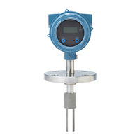
emerson Micro Motion Installation Manual (50 pages)
Fork Viscosity Meter
Brand:
emerson
| Category:
Measuring Instruments
| Size: 5.15 MB
Table of Contents
Table of Contents
3
Chapter 1 Planning
5
Installation Checklist
5
Best Practices
6
Power Requirements
6
Other Installation Considerations
8
Recommended Installations for Short-Stem Meters
11
Perform a Meter Check (Pre-Installation)
13
Chapter 2 Mounting
15
Mount in Free-Stream Application (Flanged Fitting)
15
Mount in Free-Stream Application (Weldolet Fitting)
16
Mount with a T-Piece (Flanged Fitting)
17
Mount with a Flow-Through Chamber
19
Mount in an Open Tank (Long-Stem Meter)
20
Mount in a Closed Tank (Long-Stem Meter)
23
Attach the PFA Ring and Circlip
28
Rotate the Electronics on the Meter (Optional)
29
Rotate the Display on the Transmitter (Optional)
30
Chapter 3 Wiring
33
Available Output Terminals and Wiring Requirements
33
Explosion-Proof/Flameproof or Non-Hazardous Output Wiring
34
Processor Wiring for Remote-Mount 2700 FOUNDATION Fieldbus Option
38
Wiring to External Devices (HART Multidrop)
43
Wiring to Signal Converters And/Or Flow Computers
45
Chapter 4 Grounding
47
Emerson Micro Motion Installation Manual (46 pages)
Fork Viscosity Meters
Brand:
Emerson
| Category:
Measuring Instruments
| Size: 3.92 MB
Table of Contents
Table of Contents
3
Chapter 1 Planning
5
Installation Checklist
5
Best Practices
6
Power Requirements
6
Other Installation Considerations
8
Recommended Installations for Short-Stem Meters
10
Perform a Pre-Installation Meter Check
11
Chapter 2 Mounting
13
Mount in Free-Stream Application (Flanged Fitting)
13
Mount in Free-Stream Application (Weldolet Fitting)
14
Mount with a T-Piece (Flanged Fitting)
15
Mount with a Flow-Through Chamber
17
Mount in an Open Tank (Long-Stem Meter)
18
Mount in a Closed Tank (Long-Stem Meter)
21
Attach the PFA Ring and Circlip
25
Rotate the Electronics on the Meter (Optional)
26
Rotate the Display on the Transmitter (Optional)
27
Chapter 3 Wiring
29
Terminals and Wiring Requirements
29
Explosion-Proof/Flameproof or Non-Hazardous Output Wiring
30
Processor Wiring for Remote-Mount 2700 FOUNDATION ™ Fieldbus Option
34
Wiring to External Devices (HART Multidrop)
39
Wiring to Signal Converters And/Or Flow Computers
41
Chapter 4 Grounding
43
Emerson Micro Motion Installation Manual (28 pages)
Specific Gravity Meters / Gas specific gravity measurement
Brand:
Emerson
| Category:
Measuring Instruments
| Size: 2.32 MB
Table of Contents
Table of Contents
3
Chapter 1 Planning
5
Installation and Commissioning Overview
5
Installation Checklist
5
Best Practices
6
Recommended Installation for Specific Gravity Applications
7
Power Requirements
8
Chapter 2 Mounting
11
Mount the Meter Enclosure to a Wall
11
Connect the Gas Bypass Lines
13
Rotate the Display on the Transmitter (Optional)
14
Chapter 3 Wiring
16
Terminals and Wiring Requirements
16
Intrinsically Safe Output Wiring
17
Heater Wiring
25
Chapter 4 Grounding
27
Emerson Micro Motion Quick Start Manual (12 pages)
EtherNet/IP Module
Brand:
Emerson
| Category:
Control Unit
| Size: 0.48 MB
Table of Contents
Set up the Module with MVD Direct Connect
2
Set up the Transmitter
3
Mount, Wire, and Set the Network Settings
3
Modbus Terminals
6
Led Indicators
7
Advertisement
Related Products
Emerson Micro Motion Transmitters and Discrete Controllers Series 3000
Emerson Micro Motion ELITE
Emerson Micro Motion 3300
Emerson Micro Motion 2500
Emerson Micro Motion 2000 Series
Emerson Micro Motion 4200
Emerson Micro-Motion 2400S
Emerson MicroMotion FOUNDATION 5700
Emerson MAS 2600
Emerson Micro Motion F-Series Sensor
Emerson Categories
Controller
Control Unit
Transmitter
Measuring Instruments
Fan
More Emerson Manuals
Login
Sign In
OR
Sign in with Facebook
Sign in with Google
Upload manual
Upload from disk
Upload from URL