Sign In
Upload
Manuals
Brands
Emerson Manuals
Transmitter
Micro Motion 4200
Emerson Micro Motion 4200 Manuals
Manuals and User Guides for Emerson Micro Motion 4200. We have
4
Emerson Micro Motion 4200 manuals available for free PDF download: Configuration And Use Manual, Installation Manual, User Manual
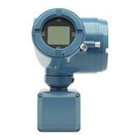
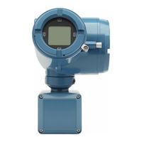
Emerson Micro Motion 4200 - 2-Wire Transmitter Manual
Brand:
Emerson
| Category:
Transmitter
| Size: 1.56 MB
Table of Contents
Return policy
Planning
Meter components
Installation types
Installation checklist
Maximum cable lengths between sensor and transmitter
Mounting and sensor wiring
Mounting and sensor wiring for integral-mount transmitters
Mount the device to a wall or instrument pole
Wire the 9-wire remote-mount unit to the sensor
Ground the meter components
Rotating the unit on the sensor (optional)
Rotating the display orientation
Rotate the sensor wiring junction box on a remote-mount transmitter (optional)
Wiring the channels
Installation types for the unit
General configuration
Connection example for cases where a barrier is required
Available channels
Barriers verified by Micro Motion
Channel power requirements
Access the wiring channels
Wire the Channel A mA HART output
Wire the Channel B mA output
Wire Frequency/Discrete output (Channel B)
Powering up the device
Configuring the unit with Guided Setup
Using the display controls
Communicating with the unit
Documents / Resources
References
Advertisement
Emerson Micro Motion 4200 Configuration And Use Manual (224 pages)
Brand:
Emerson
| Category:
Transmitter
| Size: 4.69 MB
Table of Contents
Table of Contents
3
Chapter 1 Before You Begin
7
About this Manual
7
Related Documents
7
Installation Types
7
Communication Tools and Protocols
9
Chapter 2 Quick Start
11
Applying Power
11
Check Meter Status
11
Commissioning Wizards
12
Make a Startup Connection to the Transmitter
12
Set the Transmitter Clock
12
View the Licensed Features
13
Set Informational Parameters
13
Characterize the Meter (if Required)
14
Verify Mass Flow Measurement
17
Verify the Zero
17
Chapter 3 Introduction to Configuration and Commissioning
19
Security and Write Protection
19
Work with Configuration Files
21
Chapter 4 Configure Process Measurement
23
Configure Sensor Flow Direction Arrow
23
Configure Mass Flow Measurement
24
Configure Volume Flow Measurement for Liquid Applications
28
Configure Gas Standard Volume (GSV) Flow Measurement
32
Configure Density Measurement
36
Configure Temperature Measurement
38
Configure Pressure Measurement Unit
40
Configure Velocity Measurement Unit
40
Chapter 5 Configure Process Measurement Applications
43
Set up the API Referral Application
43
Set up Concentration Measurement
56
Chapter 6 Configure Advanced Options for Process Measurement
69
Detect and Report Two-Phase Flow
69
Configure Flow Rate Switch
70
Configure Events
71
Configure Totalizers and Inventories
73
Configure Logging for Totalizers and Inventories
76
Configure Process Variable Fault Action
76
Chapter 7 Configure Device Options and Preferences
81
Configure the Transmitter Display
81
Configure the Transmitter's Response to Alerts
85
Chapter 8 Integrate the Meter with the Control System
93
Configure the Transmitter Channels
93
Configure the Ma Outputs
94
Configure the Frequency Output
102
Configure the Discrete Output
106
Chapter 9 Configure Digital Communications
109
Configure HART Communications
109
Chapter 10 Complete the Configuration
115
Test or Tune the System Using Sensor Simulation
115
Enable or Disable Software Write Protection
116
MMI-20048166 April
117
Chapter 11 Transmitter Operation
119
View Process and Diagnostic Variables
119
View and Acknowledge Status Alerts
120
Read Totalizer and Inventory Values
122
Start, Stop, and Reset Totalizers and Inventories
122
Chapter 12 Measurement Support
125
Use Smart Meter Verification (SMV)
125
Zero the Meter
132
Set up Pressure Compensation
134
Validate the Meter
139
Perform a (Standard) D1 and D2 Density Calibration
141
Chapter 13 Maintenance
145
Install a New Transmitter License
145
Reboot the Transmitter
146
Battery Replacement
146
Chapter 14 Log Files, History Files, and Service Files
147
Generate History Log Files
147
Generate Service Files
148
SMV History and SMV Log
149
Totalizer History and Log
150
Generate Service Files
151
Chapter 15 Troubleshooting
157
Overview
157
Status Alerts, Causes, and Recommendations
157
Transmitter Does Not Communicate
174
API Referral Problems
174
Concentration Measurement Problems
175
Density Measurement Problems
176
Discrete Output Problems
178
Flow Measurement Problems
179
Frequency Output Problems
181
Milliamp Output Problems
183
Temperature Measurement Problems
186
Check Power Supply Wiring
187
Check Sensor to Transmitter Wiring
188
Check Grounding
189
Perform Loop Tests
189
Trim Ma Output
193
Using Sensor Simulation for Troubleshooting
194
Check HART Communications
194
Check Lower Range Value and Upper Range Value
195
Check Ma Output Fault Action
195
Check the Scaling of the Frequency Output
195
Check Frequency Output Mode
195
Check Frequency Output Fault Action
196
Check the Direction Parameters
196
Check the Cutoffs
196
Check for Two-Phase Flow (Slug Flow)
196
Check for Radio Frequency Interference (RFI)
197
Check HART Burst Mode
197
Check the Drive Gain
197
Checking Process Variables
198
Check the Pickoff Voltage
201
Check for Internal Electrical Problems
202
Locate a Device Using the HART 7 Squawk Feature
203
Appendix A Using the Transmitter Display
205
Components of the Transmitter Display
205
Access and Use the Display Menu
206
Appendix B Using Prolink III with the Transmitter
211
Basic Information about Prolink III
211
Connect with Prolink III
212
Appendix C Using a Field Communicator with the Transmitter
215
Basic Information about the Field Communicator
215
Connect with the Field Communicator
215
Appendix D Channel Combinations
217
Rules for Channel Combinations
217
Valid Combinations for Channel Configuration
217
Appendix E Concentration Measurement Matrices, Derived Variables, and Process Variables
219
Standard Matrices for the Concentration Measurement Application
219
Derived Variables and Calculated Process Variables
220
Appendix F Environmental Compliance
223
Rohs and WEEE
223
Emerson Micro Motion 4200 Installation Manual (40 pages)
2-Wire Transmitter
Brand:
Emerson
| Category:
Transmitter
| Size: 7.77 MB
Table of Contents
Table of Contents
3
Chapter 1 Planning
5
About this Document
5
Related Documentation
5
Meter Components
5
Installation Types
6
Installation Checklist
7
Maximum Cable Lengths between Sensor and Transmitter
9
Chapter 2 Mounting and Sensor Wiring
11
Mounting and Sensor Wiring for Integral-Mount Transmitters
11
Mount the Transmitter to a Wall or Instrument Pole
11
Wire the 9-Wire Remote-Mount Transmitter to the Sensor
14
Ground the Meter Components
16
Rotating the Transmitter on the Sensor (Optional)
17
Rotating the Display Orientation
18
Rotate the Sensor Wiring Junction Box on a Remote-Mount Transmitter (Optional)
19
Chapter 3 Wiring the Channels
21
Installation Types for the 4200 Transmitter
21
Available Channels
22
Barriers Verified by Micro Motion
23
Channel Power Requirements
24
Access the Wiring Channels
28
Wire the Channel a Ma HART Output
29
Wire the Channel B Ma Output
30
Wire Frequency/Discrete Output (Channel B)
30
Wire the Ma/Sil Output
31
Chapter 4 Power up the Transmitter
33
Chapter 5 Configuring the Transmitter with Guided Setup
35
Chapter 6 Using the Display Controls
37
Configure the Display Backlight
38
Chapter 7 Communicating with the Transmitter
39
Advertisement
Emerson Micro Motion 4200 Installation Manual (40 pages)
2-Wire Transmitter
Brand:
Emerson
| Category:
Transmitter
| Size: 7.81 MB
Table of Contents
Table of Contents
3
Chapter 1 Planning
5
About this Document
5
Related Documentation
5
Meter Components
5
Installation Types
5
Installation Checklist
8
Maximum Cable Lengths between Sensor and Transmitter
10
Mounting and Sensor Wiring
11
Mounting and Sensor Wiring for Integral-Mount Transmitters
11
Mount the Transmitter to a Wall or Instrument Pole
11
Wire the 9-Wire Remote-Mount Transmitter to the Sensor
14
Ground the Meter Components
16
Rotating the Transmitter on the Sensor (Optional)
17
Rotating the Display Orientation
18
Rotate the Sensor Wiring Junction Box on a Remote-Mount Transmitter (Optional)
18
Wiring the Channels
21
Installation Types for the 4200 Transmitter
21
Available Channels
22
Barriers Verified by Micro Motion
23
Channel Power Requirements
23
Access the Wiring Channels
28
Wire the Channel a Ma HART Output
29
Wire the Channel B Ma Output
30
Wire Frequency/Discrete Output (Channel B)
30
Wire the Ma/Sil Output
31
Powering up the Transmitter
33
Configuring the Transmitter with Guided Setup
35
Using the Display Controls
37
Configure the Display Backlight
38
Communicating with the Transmitter
39
Advertisement
Related Products
Emerson Micro Motion Transmitters and Discrete Controllers Series 3000
Emerson Micro Motion
Emerson Micro Motion ELITE
Emerson Micro Motion 3300
Emerson Micro Motion 2500
Emerson Micro Motion 2000 Series
Emerson Micro-Motion 2400S
Emerson MicroMotion FOUNDATION 5700
Emerson MAS 2600
Emerson Micro Motion F-Series Sensor
Emerson Categories
Controller
Control Unit
Transmitter
Measuring Instruments
Fan
More Emerson Manuals
Login
Sign In
OR
Sign in with Facebook
Sign in with Google
Upload manual
Upload from disk
Upload from URL