Sign In
Upload
Manuals
Brands
Emerson Manuals
Transmitter
Micro-Motion 2400S
Emerson Micro-Motion 2400S Manuals
Manuals and User Guides for Emerson Micro-Motion 2400S. We have
1
Emerson Micro-Motion 2400S manual available for free PDF download: Configuration And Use Manual
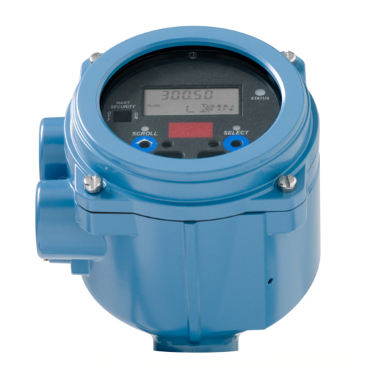
Emerson Micro-Motion 2400S Configuration And Use Manual (198 pages)
Transmitters with Analog Outputs
Brand:
Emerson
| Category:
Transmitter
| Size: 4.3 MB
Table of Contents
Table of Contents
3
Chapter 1 Before You Begin
9
Overview
9
Safety
9
Determining Transmitter Information
9
Determining Version Information
10
Flowmeter Documentation
10
Communication Tools
10
Planning the Configuration
11
Pre-Configuration Worksheet
11
Micro Motion Customer Service
12
Chapter 2 Using the Transmitter User Interface
13
Overview
13
User Interface Without or with Display
13
Removing and Replacing the Transmitter Housing Cover
15
Using the Optical Switches
15
Using the Display
15
Display Language
15
Viewing Process Variables
16
Using Display Menus
16
Display Password
17
Entering Floating-Point Values with the LCD
17
Using the HART Security Switch
19
Chapter 3 Connecting with Prolink II or Pocket Prolink Software
21
Overview
21
Requirements
21
Configuration Upload/Download
21
Connecting from a PC to a Model 2400S an Transmitter
22
Service Port Connections
22
Connecting to the HART Clips or to a HART Multidrop Network
24
Prolink II Language
26
Chapter 4 Connecting with the 375 Field Communicator
27
Overview
27
Communicator Device Descriptions
27
Connecting to a Transmitter
28
Connecting to HART Clips
28
Connecting to a Multidrop Network
29
Conventions Used in this Manual
29
Communicator Safety Messages and Notes
29
Chapter 5 Flowmeter Startup
31
Overview
31
Applying Power
32
Performing a Loop Test
32
Trimming the Milliamp Output
36
Zeroing the Flowmeter
38
Preparing for Zero
38
Zero Procedure
39
Chapter 6 Required Transmitter Configuration
43
Overview
43
Characterizing the Flowmeter
44
When to Characterize
44
Characterization Parameters
44
How to Characterize
45
Configuring Transmitter Channels
46
Configuring the Measurement Units
47
Mass Flow Units
47
Volume Flow Units
48
Density Units
50
Temperature Units
51
Pressure Units
51
Configuring the Ma Output
52
Configuring the Process Variable
53
Configuring the Ma Output Range (LRV and URV)
53
Configuring the AO Cutoff
53
Configuring Added Damping
54
Configuring the Fault Indicator and Fault Value
55
Configuring the Frequency Output
56
Configuring the Process Variable
57
Configuring the Output Scale
57
Configuring the Maximum Pulse Width
58
Configuring the Frequency Output Polarity
59
Configuring the Fault Indicator
60
Configuring the Discrete Output
60
Polarity
61
Assignment
62
Fault Action
63
Configuring the Discrete Input
63
Assignment
64
Polarity
64
Chapter 7 Using the Transmitter
67
Overview
67
Recording Process Variables
67
Viewing Process Variables
68
With the Display
68
With Prolink II
68
With the Communicator
68
Viewing Transmitter Status
69
Using the Status LED
69
Using Prolink II
69
Using the Communicator
69
Handling Status Alarms
70
Using the Display Menus
70
Using Prolink II
71
Using the Communicator
71
Using the Totalizers and Inventories
72
Viewing Current Totals for Totalizers and Inventories
72
Controlling Totalizers and Inventories
73
Chapter 8 Optional Configuration
77
Overview
77
Configuring Volume Flow Measurement for Gas
78
Creating Special Measurement Units
79
About Special Measurement Units
79
Special Measurement Unit for Mass Flow
80
Special Measurement Unit for Liquid Volume Flow
81
Special Measurement Unit for Gas Standard Volume Flow
81
Configuring Cutoffs
81
Cutoffs and Volume Flow
82
Configuring the Damping Values
82
Interaction with the AO Cutoff
82
Damping and Volume Measurement
83
Interaction with the Added Damping Parameter
83
Configuring the Flow Direction Parameter
83
Configuring Events
87
Defining Events
88
Checking and Reporting Event Status
89
Configuring Slug Flow Limits and Duration
89
Configuring Fault Handling
90
Status Alarm Severity
90
Fault Timeout
93
Configuring the Display
93
Update Period
93
Language
94
Enabling and Disabling Display Parameters
94
Configuring the LCD Backlight
95
Configuring the Display Variables and Display Precision
95
Configuring Digital Communications
96
Configuring Addresses and Related Parameters
96
Infrared Port Write-Protection
98
Floating-Point Byte Order
98
Additional Communications Response Delay
98
Configuring the Digital Fault Indicator
99
Configuring Burst Mode
99
Configuring the PV, SV, TV, and QV Assignments
100
Configuring Device Settings
102
Configuring Sensor Parameters
102
Chapter 9 Pressure Compensation, Temperature Compensation, and Polling
103
Overview
103
Pressure Compensation
103
Options
103
Pressure Correction Factors
104
Configuration
104
External Temperature Compensation
105
Polling Setup
107
Chapter 10 Measurement Performance
109
Overview
109
Meter Validation, Meter Verification, and Calibration
109
Meter Verification
109
Meter Validation and Meter Factors
111
Calibration
111
Comparison and Recommendations
112
Performing Meter Verification
113
Preparing for the Meter Verification Test
113
Running the Meter Verification Test, Original Version
113
Running Smart Meter Verification
116
Reading and Interpreting Meter Verification Test Results
121
Setting up Automatic or Remote Execution of the Meter Verification Test
127
Performing Meter Validation
130
Performing Density Calibration
131
Preparing for Density Calibration
131
Density Calibration Procedures
132
Performing Temperature Calibration
137
Chapter 11 Troubleshooting
139
Overview
139
Guide to Troubleshooting Topics
139
Micro Motion Customer Service
140
Transmitter Does Not Operate
140
Transmitter Does Not Communicate
140
Zero or Calibration Failure
141
Fault Conditions
141
HART Output Problems
141
I/O Problems
141
11.10 Simulation Mode
144
Transmitter Status LED
145
Status Alarms
145
Checking Process Variables
150
Diagnosing Wiring Problems
152
Checking the Power Supply Wiring
153
Checking Grounding
153
Checking for RF Interference
153
Checking the HART Communication Loop
154
Checking the Communication Device
154
Checking the Output Wiring and Receiving Device
155
Checking Slug Flow
155
11.18 Checking the Sensor Tubes
155
Checking Output Saturation
155
Checking the HART Address and Loop Current Mode Parameter
156
Checking the Flow Measurement Configuration
156
Checking the Characterization
156
Checking the Calibration
156
Checking the Test Points
157
Obtaining the Test Points
157
Evaluating the Test Points
157
Drive Gain Problems
158
Low Pickoff Voltage
158
Checking Sensor Circuitry
159
Appendix A Default Values and Ranges
163
Overview
163
Most Frequently Used Defaults and Ranges
163
Appendix B Flowmeter Installation Types and Components
167
Overview
167
Transmitter Components
167
Terminal Diagrams
167
Appendix C Menu Flowcharts - Model 2400S an Transmitters
169
Overview
169
Version Information
169
Appendix D Display Codes and Abbreviations
187
Overview
187
Codes and Abbreviations
187
Index
191
Advertisement
Advertisement
Related Products
Emerson Micro Motion Transmitters and Discrete Controllers Series 3000
Emerson Micro Motion
Emerson Micro Motion ELITE
Emerson Micro Motion 3300
Emerson Micro Motion 2500
Emerson Micro Motion 2000 Series
Emerson Micro Motion 4200
Emerson MicroMotion FOUNDATION 5700
Emerson MAS 2600
Emerson Micro Motion F-Series Sensor
Emerson Categories
Controller
Control Unit
Transmitter
Measuring Instruments
Fan
More Emerson Manuals
Login
Sign In
OR
Sign in with Facebook
Sign in with Google
Upload manual
Upload from disk
Upload from URL