User Manuals: Daikin FLXS25BVMA Air Conditioner
Manuals and User Guides for Daikin FLXS25BVMA Air Conditioner. We have 6 Daikin FLXS25BVMA Air Conditioner manuals available for free PDF download: Service Manual, Operation Manual, Overview, Service Manual Removal Procedure
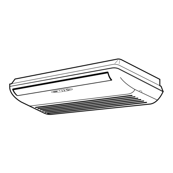
Daikin FLXS25BVMA Service Manual (403 pages)
Super Multi NX D/E Series
Brand: Daikin
|
Category: Air Conditioner
|
Size: 22 MB
Table of Contents
Advertisement
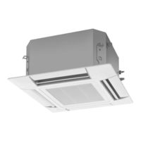
Daikin FLXS25BVMA Service Manual (298 pages)
Super Multi NX C-Series
Brand: Daikin
|
Category: Air Conditioner
|
Size: 13 MB
Table of Contents
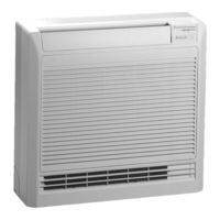
Daikin FLXS25BVMA Service Manual (298 pages)
Super multi NX
C-series
Brand: Daikin
|
Category: Air conditioning
|
Size: 7 MB
Table of Contents
Advertisement

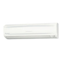
Daikin FLXS25BVMA Operation Manual (30 pages)
Inverter
Brand: Daikin
|
Category: Air Conditioner
|
Size: 2 MB
Table of Contents
Daikin FLXS25BVMA Overview (22 pages)
Multi-Split Type Air Conditioners L series With DC Inverter and Swing Compressor Cooling Only & Heat Pump [50 Hz]
Brand: Daikin
|
Category: Air Conditioner
|
Size: 4 MB
Table of Contents

Advertisement