Sign In
Upload
Manuals
Brands
Audi Manuals
Automobile
A6 2005 - Electrics
Audi A6 2005 - Electrics Manuals
Manuals and User Guides for Audi A6 2005 - Electrics. We have
6
Audi A6 2005 - Electrics manuals available for free PDF download: Repair Manual, Workshop Manual, Service Training, Service
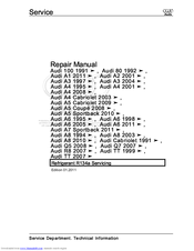
Audi A6 2005 - Electrics Workshop Manual (198 pages)
Brand:
Audi
| Category:
Automobile
| Size: 3 MB
Table of Contents
Table of Contents
3
Technical Data
7
Allocation of PR Number (Factory Code) to Brake Components
7
Brakes, Technical Data
7
Assessment of Ceramic Brake Discs
12
Visible Features of Ceramic Brake Discs
12
Superficial Cracks in Cooling Channel Lands
13
Cracks in Area of Bolted Connection on Ceramic Brake Discs
13
Edge Fractures
14
Chipping on Ceramic Brake Discs
14
Cracks Extending into Cooling Channels
15
Assessing Degree of Wear on Ceramic Brake Discs
16
Wear Assessment by Checking Thickness of Brake Disc
19
Wear Assessment According to Wear Indicators
20
Wear Assessment by Weighing Brake Disc
21
Wear Assessment of Ceramic Brake Disc with Tester VAS 6813
22
Brake Test
29
General Notes
29
Vehicles with Front-Wheel Drive
29
Vehicles with Four-Wheel Drive
29
Electromechanical Parking Brake on Brake Test Equipment
30
Brake Fluid
31
General Notes
31
Anti-Lock Brake System
32
General Information on the Anti-Lock Brake System
32
Notes for Repair Work on the ABS
32
Connecting Vehicle Diagnostic, Testing and Information System VAS 5051B or VAS 5052 and Selecting Functions
34
Exploded View - ABS/ESP Components
36
Anti-Lock Brake System (ABS) Bosch 8.0
41
Hydraulic Unit and Brake Lines
41
Removing and Installing Hydraulic Control Unit
42
Removing and Installing Hydraulic Control Unit - S6 and RS 6
46
Removing and Installing Parts of ABS System on Front and Rear Axles
52
Removing and Installing Parts of ABS System on Front Axle
52
Removing and Installing Front Wheel Speed Sensor
52
Removing and Installing Parts of ABS System on Rear Axle
53
Removing and Installing Rear Wheel Speed Sensor
55
Removing and Installing Parts of ESP System
56
Removing and Installing Brake Light Switch
56
Removing and Installing Brake Light Sensor
57
Removing and Installing ESP Sensor Unit G419
58
Removing and Installing Steering Angle Sender G85
59
Removing and Installing Parking Brake Contact Switch F321
60
Removing and Installing Brake Pressure Sender G518 and Brake Pressure Sender G519
60
Brakes - Mechanism
62
Front Brakes FN3 (PR 1LT)
62
Servicing Front Brakes (PR 1LT)
62
Removing and Installing Brake Pads (1LT)
64
Front Brakes FNR G60 (PR 1LG/1LD/1LH/1LV/1ZL)
68
Servicing Front Brakes (PR 1LG/1LD/1LH/1LV/1ZL)
68
Removing and Installing Brake Pads (PR 1LG/1LD/1LH/1LV/1ZL)
70
Front Brakes (PR 1LJ/1LL)
76
Servicing Front Brakes (PR 1LJ/1LL)
76
Removing and Installing Brake Pads (PR 1LJ/1LL)
78
Front Brakes (Steel Version) - RS 6
83
Servicing Front Brakes (Steel Version) - RS 6
83
Detaching and Attaching Front Brake Caliper - RS 6
84
Renewing Front Brake Caliper (RS 6)
85
Removing and Installing Front Brake Pads - RS 6
87
Detaching and Attaching Front Brake Disc - RS 6
91
Renewing Front Brake Disc - RS 6
92
Ceramic Front Brakes
94
Servicing Ceramic Front Brakes
94
Detaching and Attaching Front Brake Caliper (Ceramic Brakes)
96
Renewing Front Brake Caliper (Ceramic Brakes)
98
Removing and Installing Front Brake Pads (Ceramic Brakes)
101
Detaching and Attaching Front Brake Disc (Ceramic Brakes)
106
Renewing Front Brake Disc (Ceramic Brakes)
107
Rear Brakes, Electronic Parking Brake and Handbrake (EPB)
110
Servicing Rear Brakes (Including Ceramic Brakes) - All Models
110
Removing and Installing Brake Pads
113
Exploded View - Brake Pedal, Left-Hand Drive Vehicles with Manual Gearbox
119
Removing and Installing Brake Pedal - Left-Hand Drive Vehicles
120
Exploded View - Brake Pedal, Left-Hand Drive Vehicles with Automatic Gearbox
121
Exploded View - Brake Pedal, Right-Hand Drive Vehicles
122
Removing and Installing Brake Pedal - Right-Hand Drive Vehicles
123
Separating Brake Pedal from Brake Servo
124
Removing and Installing Mounting Bracket
126
Overview of Components - Electronic Parking Brake and Handbrake (EPB)
130
Removing and Installing Electric Park and Handbrake Control Unit J540
131
Removing and Installing Actuator Motor for Electronic Parking Brake and Handbrake
132
Brakes - Hydraulics
135
Pressurised Leak Test
135
High-Pressure and Low-Pressure Tests
135
Brake Caliper FN3
136
Servicing Brake Calipers
136
Removing and Installing Piston for Front Brake Caliper
137
Brake Caliper FNR G60
140
Servicing Brake Calipers
140
Removing and Installing Piston for Front Brake Caliper
141
Brake Calipers 2FNR 42 al
144
Servicing Brake Calipers
144
Removing and Installing Piston for Front Brake Caliper
145
Servicing Brake Calipers (Steel Version) - RS 6
148
Removing and Installing Piston for Front Brake Caliper
148
Servicing Front Brake Calipers (Ceramic Brakes) - RS 6
152
Removing and Installing Pistons for Front Brake Caliper (Ceramic Brakes)
153
Rear Brake Calipers for Electronic Parking Brake and Handbrake (EPB)
155
Servicing Brake Calipers
155
Removing and Installing Piston for Rear Brake Caliper
156
Bleeding Brake System
160
Bleeding Hydraulic System with Brake Filling and Bleeding Equipment
161
Bleeding Hydraulic System Without Brake Filling and Bleeding Equipment
163
Changing Brake Fluid
165
Exploded View - Brake Servo / Brake Master Cylinder
166
Removing and Installing Brake Master Cylinder
168
Brake Servo
171
Removing and Installing Brake Servo
171
Vacuum Pumps for Brake Servo
174
Exploded View - Vacuum Pump for Brake Servo
174
Removing and Installing Vacuum Pump
175
Removing and Installing Vacuum Pump - Vehicles with 2.0 Ltr. Petrol Engine
176
Removing and Installing Vacuum Pump - Vehicles with 2.4 Ltr. Petrol Engine
179
Removing and Installing Vacuum Pump - Vehicles with 2.8 Ltr. Petrol Engine
180
Removing and Installing Vacuum Pump - Vehicles with 3.0 Ltr. Petrol Engine
181
Removing and Installing Vacuum Pump - Vehicles with 3.2 Ltr. Petrol Engine
182
Exploded View - Vacuum Pump, RS 6
183
Removing and Installing Vacuum Pump - RS 6
184
Removing and Installing Vacuum Pump - Vehicles with Diesel Engine
185
Removing and Installing Vacuum Pump - Vehicles with 2.7 Ltr. TDI and 3.0 Ltr. TDI Diesel Engine
187
Checking Electric Vacuum Pump for Brakes V192
189
Exploded View - Electric Vacuum Pump for Brakes V192
191
Removing and Installing Electric Vacuum Pump
191
Removing and Installing Electric Vacuum Pump - S6
194
Brake Servo Pressure Sensor G294
195
Removing and Installing Pressure Sensor
195
Checking Non-Return Valve
196
Checking Non-Return Valve - S6
196
Brake Hoses and Brake Lines
197
Routing of Brake Hoses/Lines
197
Advertisement
Audi A6 2005 - Electrics Repair Manual (211 pages)
Vehicle air conditioning systems
Brand:
Audi
| Category:
Air Conditioner
| Size: 1 MB
Table of Contents
Table of Contents
3
General, Technical Data
5
1 General Information
5
A/C System
5
Refrigerant Oil
11
Safety Precautions
12
Laws and Regulations
16
A/C System Principles
22
1.4 Refrigerant Circuit and Components
25
Refrigerant Circuit and Components
25
Component Replacement
26
Connections for Quick-Release Coupling on Refriger- Ant Circuit
28
O-Ring Seals
28
Refrigerant Circuit Connections with Valve for Switches
30
Refrigerant Circuit Pipes and Hoses
30
Refrigerant Circuit, Cleaning
31
Refrigerant Circuit, Converting R12 to R134A
31
Refrigerant Circuit, Flushing
32
Refrigerant Circuit Flushing with Compressed Air and Nitrogen
33
Refrigerant Circuit Flushing with Refrigerant R134A
36
Refrigerant Circuit, Repairing
43
Switches and Sensors
43
2 Description and Operation
45
Refrigerant Circuit
45
Refrigerant Circuit Precautions
45
Ball Valve
63
Pressure Relief Valve
72
Switches and Sensors on Refrigerant Circuit and Connections
78
Electrical Components Not on Refrigerant Circuit
82
2.4 A/C Service Station
83
A/C Service Station
83
Using Service Station
84
Charging Refrigerant Circuit
87
Connecting for Measuring and Testing, Two Service Connections
87
Connecting for Measuring and Testing, One Service Connection
88
Connecting for Measuring and Testing, no Service Connection
89
Connecting with Air Conditioning Adapter Set V.A.G 1786
90
Connecting with Adapter Set VAG1785/10
91
Draining Refrigerant Circuit
91
Draining Service Station
92
Evacuating Refrigerant Circuit
93
Transferring Refrigerant to Reservoir (Charging Cylinder or Reservoir Bottle) of Service Station
97
3 Specifications
98
Charging Refrigerant
98
Refrigerant R134A Capacities
98
Capacities, Audi A3 (8L_) 1997 through MY 2004 and Audi TT (8N_), from MY 1999
100
Capacities, Audi A3 (8P_) from MY 04
103
Capacities, Audi TT (8J_) from MY 07
104
Capacities, Audi 80 (8A_/8C_), Audi Coupe (8B_) and Audi Cabriolet (8G_), from MY 2002
105
Capacities, Audi A4 (8D_), from MY 95
105
Audi A5 Cabriolet (8F_) from MY 2009
109
Capacities, Audi A4 (8K_) from MY 2008, Audi A5
109
Capacities, Audi 100 and Audi A6 (4A_), from MY 98
110
Capacities, Audi A6 (4B_) from MY 1998 and Audi Allroad (4B_) from MY 2005
111
Capacities, Audi A6 (4F_), from MY 05
116
Capacities, Audi V8 (4C_) from MY 94
117
Capacities, Audi A8 (4D_) from MY 94
118
Capacities, Audi A8 (4E_) from MY 03
119
Capacities, Audi A8 (4H_) from MY 10
119
Features of the Refrigerant System
119
Refrigerant Oils
121
3.4 Refrigerant Oil Capacities
123
Refrigerant Oil Capacities
123
At Start of Production, A/C Compressors Manufactured by
125
Led. Refer to Electronic Parts Catalog (ETKA) and ⇒ Heating
125
Ventilation and Air Conditioning; Rep. Gr. 87 ; Removal and
125
Depending on the Engine, an A/C Compressor Manufactured
125
Time (Introduction Still Open). Refer to Electronic Parts Catalog
125
(ETKA) and ⇒ Heating, Ventilation and Air Conditioning; Rep
125
Gr. 87 ; Removal and Installation
125
Capacities, Audi A2 (8Z_) from MY 01
125
Restrictor (Colored)
125
Removal and Installation
126
Capacities, Audi A3 (8L_) 1997 through MY 2004 and Audi TT (8N_), from MY 1999
126
Capacities, Audi A3 (8P_) from MY 04
127
Capacities, Audi TT (8J_) from MY 07
128
Capacities, Audi 80 (8A_/8C_), Audi Coupe (8B_) and Audi Cabriolet (8G_), from MY 2002
129
3.4.7 Capacities, Audi A4 (8D_), from My 95
130
Vehicle Mod-Production Period Total Quantity of Oil in Refrig-Quantity of Refrigerant Oil in Replace- el Erant Circuit in CM 3 Ment Compressor in CM
133
As of 04.97
134
The Replacement Compressor Contains the Full Quantity of Oil
134
Intended for the Refrigerant Circuit. on A/C Compressor Re
134
Placement, the Quantity of Oil in the A/C Compressor Is There
134
Fore to be Adjusted. Refer to
134
Beginning the Production Year 2006, the Name of the Zexel a
134
C Compressor was Changed from Zexel to Valeo
134
Vehicle Mod-Production Period Total Quantity of Oil in Refrig-Quantity of Refrigerant Oil in Replace- el Erant Circuit in CM 3 Ment Compressor in CM
136
As of
141
4 Diagnosis and Testing
146
Pressure Gauge, Tests and Measurements
146
Leak Detection
147
Refrigerant Circuit Concerns
155
Pressures, Checking
157
5 Removal and Installation
195
Leaking or Damaged Components Except A/C Compressor, Accumulator or Receiver - Circuit Empty of Refrigerant
195
Leaking or Damaged Components Except A/C Compressor, Accumulator or Receiver - Circuit Contains Refrigerant
197
Compressor, Replacing Without Flushing Refrigerant Circuit
197
Compressor, Replacing Due to Leakage or Internal Damage
198
Receiver or Accumulator and Restrictor, Replacing after Cleaning Refrigerant Circuit
199
Receiver or Accumulator, Replacing Without Flushing Refrigerant Circuit
200
Dryer Cartridge and Dryer Bag, Replacing Without Flushing Refrigerant Circuit
201
6 Special Tools
202
Commercially Available Tools and Materials
202
Improvised Tools
207
Audi A6 2005 - Electrics Service Training (93 pages)
Brand:
Audi
| Category:
Automobile
| Size: 4 MB
Table of Contents
Table of Contents
3
Overview
4
Control Unit Installation Positions
4
Bus Topology
6
Installation Positions of Fuses and Relays
8
Convenience Electrics
10
Control Unit for Power Management J644
10
Battery Condition
10
Advantages of the Battery Condition
10
Steady Battery Discharge
11
History Data
11
Open-Circuit Voltage History
11
Battery Change History
11
Access and Start Authorisation
12
Function Diagram
12
System Overview
14
Division of Functions
16
Switch for Access and Start Authorisation E415
17
Versions
17
Functions
17
Control Unit for Access and Start Authorisation J518
19
Terminal Control
19
Locking the Steering Column
19
Immobiliser and Component Protection
19
CAN Communication
20
Vehicle Key
21
Signals from the Key LED
21
Antenna Read-In Unit for Keyless Access Authorisation J723
22
Sensors for Outer Door Handle Contact G415 - G418
22
Antennae for Access and Start Authorisation E134 - R138
23
Button for Access and Start Authorisation E408
23
Opening the Vehicle
24
Starting the Vehicle Using the Button
26
Immobiliser and Component Protection
28
New Identity
29
Component Protection
29
External Lights
30
Front Headlights
30
Halogen Headlights
30
Bi-Xenon Headlights
31
Adaptive Light
32
No Pivoting When Vehicle Is Stationary
32
Internal Structure
33
Signal and Data Exchange
34
Show Room Function
34
Back Lights
35
Basic Variant ECE
35
High Variant ECE
36
High Variant SAE
37
LED Unit Diagnosis
37
Control Unit in Dash Panel Insert J285
38
Lamp Failure
38
Outside Temperature Indicator
38
Legend
39
E493 Operating Button for Dash Panel Insert
39
Additional Signal
39
Control Unit for On-Board Power Supply J519
40
Master Functions
40
Stand-By Master Function
40
Emergency Function
41
Other Functionalities
41
Installation Position
41
Diagnosis
45
Basic Settings
45
Actuator Test
45
Coding
45
Sensor for Rain and Light Detection G397
46
Switch-On Conditions
46
Function of the Light Sensor
47
Tasks of the Rain Sensor
47
Activation
47
Function of the Rain Sensor
48
Control Unit for Wiper Motor J400
49
Control Unit 2 for On-Board Power Supply J520
50
Tilt Sensor for Anti-Theft Warning System
52
Central Control Unit for Convenience System J393
53
Interior Lighting Control
55
Standard Equipment Function
55
Additional Equipment Function (Light Package)
55
Parking Aid Control Unit J446
59
Input and Output Signals
60
4-Channel System Control Units:
60
8-Channel System Control Units:
60
Door Control Units J386 - J389
61
Stand-
61
Control Units for Seat Adjustment
63
Seat Symmetry Positioning
65
Comfort Side View
65
Memory Retrieval
65
Personal Button Memory
65
Infotainment
66
Multimedia Interface (MMI)
66
Equipment Versions
66
Display Elements in the Optimum Field of Vision
66
MMI Basic
67
MMI Basic Plus
68
MMI Basic Navigation
69
MMI High
70
Function Overview and Menu Structure of the MMI Operator System
71
Info Main Menu
72
Info Setup
72
Car Main Menu
72
Setup Main Menu
72
Antenna Systems
73
Installed Antenna Modules for Possible Vehicle Equipment
73
Control Unit for Front Information J523
74
Diagnosis on the Control Unit for Front Information J523
76
Overview of the Available Diagnostic Functions for each Module
76
Overview of the Measured-Value Blocks Available for Individual Modules
77
Coding Variants of the Control Unit for Front Information J523
78
Infotainment Control Unit Holder
78
Sound Systems
79
Standard Sound System
80
Standard Sound System Diagnosis
81
Available Actuator Tests
81
BOSE Sound System
82
BOSE Sound System Diagnosis
82
Available Telephone Systems
84
Voice Operation
85
Handsfree Operation
86
Echo and Noise Compensation
86
Mobile Baseplate Diagnosis
87
Measured-Value Blocks
87
Possible Actuator Tests
88
Mobile Baseplate Adaptation
88
SSP 323 Audi A6 ´05
91
SSP 324 Audi A6 ´05 Chassis
91
SSP 325 Audi A6 ´05 Engines and Gears
91
Advertisement
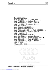
Audi A6 2005 - Electrics Repair Manual (113 pages)
Wheel and Tire
Brand:
Audi
| Category:
Automobile
| Size: 2 MB
Table of Contents
Table of Contents
3
1 General Information
5
Wheels and Tires
5
Wheels, Tires, Wheel Alignment
5
Documents and Designations
7
Legal and Technical Requirements for Retrofitting Wheel and Tire Combinations
9
Run-Flat Tire Safety Precautions
10
Run-Flat Tire Installation Instructions
11
Additional Wheel Housing Enlargement, FLAPS
12
Rolling Resistance Tires
12
Multipart Composite Wheels
13
Wheel Bolts
13
Wheel Rims with Glued-On Wheel Trim
13
Wheel Rims, Preparing
15
Tire Requirement and Maintenance
16
Driving Style
20
Snow Chains
26
Tire Wear and Service Life
30
Tires, Rolling Noises
34
Wheels and Tires, Vibration
37
Balancing
38
Finish Balancer
42
Vehicle Pulls to One Side
46
Tire Damage
48
Impact Damage
51
Tire Pressure Monitoring System
56
Wheel Repair Kit
56
Pressure Sensor
57
Emergency Wheels
58
Tires with Emergency Running Characteristics, PAX
58
Tires with Emergency Running Characteristics, SST (Self-Supporting Tire)
65
2 Description and Operation
69
Disc Wheel Design Overview, Wheel Rims
69
Light Alloy Wheels Component Overview
71
Tires with Emergency Running Characteristics (PAX) Component Overview
73
Tire Side Wall Lettering Overview
74
Tire Pressure Monitoring System Assembly Overview
77
Fastener Tightening Specifications
79
3 Specifications
79
Wheel Bolt Tightening Specifications
79
4 Diagnosis and Testing
81
Vehicle Pulls to One Side, Correcting
81
Wheel Rotation, Non-Directional Tires
82
Wheel Rotation, Directional Tires
83
Wheels and Tires, Radial and Lateral Run Out, Checking with Tire Dial Gauge
84
Wheels and Tires, Radial and Lateral Run-Out, Checking with VAG 1435
84
Rim Radial and Lateral Run Out, Checking
85
5 Removal and Installation
87
Wheel, Changing and Mounting
87
Metal Valve Body
91
Wheel Electronics, TPMS, Beru System
96
Wheel Electronics, TPMS, Siemens System
96
Wheel Rims with Replaceable Decorative Trim, Attached with Bolts
97
Wheel Rims with Replaceable Decorative Trim, Glued
97
Tires, Changing
100
Tires, with Run-Flat Tires
102
Tires, Sealed with Sealant
106
6 Special Tools
108
Audi A6 2005 - Electrics Service (76 pages)
Self-Study Programme 323
Brand:
Audi
| Category:
Automobile
| Size: 7 MB
Table of Contents
Table of Contents
4
Chapter 1 Introduction
6
Product Highlights
6
Dimensions
7
Body Shell / Connection Technology
8
Materials
10
Blanks
12
Assemblies
14
Bumpers
16
Trailer Coupling
17
Chapter 3 Passenger Protection
20
Safety System
20
Airbag Control Unit J234
22
Data Exchange
23
Sensors
24
Belt Warning
26
Airbag
27
Passenger Protection
28
Airbag Disabling Key Switch, Front Passenger Side E224
31
Seat Belts and Belt Tensioners N153 and N154
31
Active Head Restraints
33
Active Headrests
33
Battery Cut-Off Relay J655
34
Seat Occupied Recognition, Not for USA
36
Seat Occupied Recognition for USA Market
37
Seat Occupied Recognition Control Unit J706
40
Chapter 4 Diagnosis
42
Vas 5053
42
Vas 5051
43
Vas 5053/20
44
Recording the Working Time Using the VAS 5051/5052
45
Chapter 5 Engine / Gearbox
46
Overview of Available Engine / Gearbox Combinations
46
Chapter 6 Chassis
48
Overview
48
Front Axle
48
Rear Axle
49
Wheel Brake
50
Esp
51
Electromechanical Parking Brake - EPB
51
Steering System
52
Wheels / Tires
53
Tire Pressure Control System
53
Tyre Pressure Monitoring System
53
Chapter 7 Electrics
54
Bus Topology
54
In/Outputs on Control Units J393, J519 and J520
56
Chapter 8 Air Conditioning
58
Overview
58
Convenience Automatic Air Conditioning and Convenience Automatic
60
Air Conditioning Plus
60
CAN Networking
61
Components in the Audi A6´05 Air Conditioning Unit
64
Replacing Components
66
Control Motor Versions
68
In/Output Signals at Climatronic Control Unit J255
69
Additional Electric Air Heater
71
Auxiliary / Additional Heating
72
Air Conditioning Diagnosis
74
Special Tools for the Audi A6´05 Air Conditioning System
75
Audi A6 2005 - Electrics Service (15 pages)
Brand:
Audi
| Category:
Automobile
| Size: 1 MB
Table of Contents
Table of Contents
3
Introduction
4
Body
5
Occupant Protection
6
Engine
8
Running Gear
12
Advertisement
Related Products
Audi A6 242
Audi A6 2011
Audi A6 2021
Audi A6 2018
Audi A6 2024
Audi A6 2017
Audi A6 2015
Audi A6 2016
Audi A6 Avant '05 344
Audi A6 Quattro 2008
Audi Categories
Automobile
Automobile Accessories
Engine
Car Navigation system
Car Receiver
More Audi Manuals
Login
Sign In
OR
Sign in with Facebook
Sign in with Google
Upload manual
Upload from disk
Upload from URL