
Related Manuals for Intel SC5650-DP


Summary of Contents for Intel SC5650-DP
- Page 1 ® Intel Server Chassis SC5650-DP/WS/BRP/UP Service Guide ® A Guide for Technically Qualified Assemblers of Intel Identified Subassemblies/Products Intel Order Number E55434-003...
- Page 2 Intel products are not designed, intended or authorized for use in any medical, life saving, or life sustaining applications or for any other application in which the failure of the Intel product could create a situation where personal injury or death may occur.
-
Page 3: Safety Information
Safety Information Important Safety Instructions Read all caution and safety statements in this document before performing any of the instructions. See also Intel Server Boards and Server Chassis Safety Information on the ® Intel Server Deployment Toolkit CD and/or at http://support.intel.com/support/... -
Page 4: Warnings
Take care to grip with, but not squeeze, the pliers or other tool you use to remove a jumper, or you may bend or break the pins on the board. ® Intel Server Chassis SC5650-DP/WS/BRP/UP Service Guide... -
Page 5: Preface
® information, and instructions on how to add and replace components on the Intel Server Chassis SC5650. For the latest version of this manual, see: http://support.intel.com/ support/motherboards/server/chassis/sc5650/. -
Page 6: Additional Information And Software
® If you just received this Intel Server Chassis SC5650 Quick Start User's Guide in the product and need to install product box ® Intel Server Chassis SC5650-DP/WS/BRP/UP Service Guide... - Page 7 To make sure your system Power Budget Tool at: falls within the allowed http://support.intel.com/support/motherboards/server/s5500BC power budget Intel ® System Management Software For software to manage ® your Intel server ® Intel Server Chassis SC5650-DP/WS/BRP/UP Service Guide...
- Page 8 Preface ® viii Intel Server Chassis SC5650-DP/WS/BRP/UP Service Guide...
-
Page 9: Table Of Contents
Installing and Removing a Fixed Hard Drive ...............24 Installing a Fixed Hard Drive ..................24 Removing a Fixed Hard Drive ..................30 Installing or Removing a DVD-ROM or CD-ROM Drive ............33 Installing a DVD-ROM or CD-ROM Drive ..............33 ® Intel Server Chassis SC5650-DP/WS/BRP/UP Service Guide... - Page 10 Intended Application Uses ..................100 Site Selection ......................100 Equipment Handling Practices .................. 100 Power and Electrical Warnings ................. 101 Access Warnings ...................... 101 Electrostatic Discharge (ESD) ................... 102 Other Hazards ......................102 Deutsch ..........................103 ® Intel Server Chassis SC5650-DP/WS/BRP/UP Service Guide...
- Page 11 Extent of Limited Warranty ....................143 Warranty Limitations and Exclusions .................144 Limitations of Liability ....................144 How to Obtain Warranty Service ..................144 Telephone Support ....................145 Returning a Defective Product ...................145 F. Regulatory and Compliance Information ............147 ® Intel Server Chassis SC5650-DP/WS/BRP/UP Service Guide...
- Page 12 VCCI (Japan) ......................153 BSMI (Taiwan) ......................153 Korean Compliance (RRL) ..................154 CNCA (CCC-China) ....................154 Regulated Specified Components ................154 Restriction of Hazardous Substances (RoHS) Compliance ..........155 End-of-Life / Product Recycling ..................155 ® Intel Server Chassis SC5650-DP/WS/BRP/UP Service Guide...
- Page 13 List of Figures ® Figure 1. Front View of Intel Server Chassis SC5650.............. 1 Figure 2. Front View Components (with Front Bezel Assembly)..........3 Figure 3. Front View Components (without Front Bezel Assembly)........... 4 Figure 4. Internal Components (DP/WS/BRP Configuration Shown)......... 5 Figure 5.
- Page 14 Figure 82. Attaching Fan Bracket to Expanded Hot Swap Drive Cage........66 Figure 83. Attaching Fan Bracket to Non-Expanded Hot Swap Drive Cage......67 Figure 84. Attaching Fan to Fan Bracket ................. 68 ® Intel Server Chassis SC5650-DP/WS/BRP/UP Service Guide...
- Page 15 Figure 113. Detaching Inner Rack Rail from Rack Rail Assembly ........... 90 Figure 114. Attaching Inner Rack Rails to Chassis (DP/WS/BRP configuration shown) ..91 Figure 115. Attaching Outer Rack Rails to Rack Uprights ............92 Figure 116. Installing Chassis into Rack .................. 93 ® Intel Server Chassis SC5650-DP/WS/BRP/UP Service Guide...
- Page 16 ® Intel Server Chassis SC5650-DP/WS/BRP/UP Service Guide...
- Page 17 Table 5. 600-W Power Supply Output Capability ..............96 Table 6. 1000-W Power Supply Output Capability ..............96 Table 7. DP 400-W Power Supply Output Capability ............... 97 Table 8. System Environmental Specifications ................ 97 ® Intel Server Chassis SC5650-DP/WS/BRP/UP Service Guide xvii...
- Page 18 ® xviii Intel Server Chassis SC5650-DP/WS/BRP/UP Service Guide...
-
Page 19: Server Chassis Features
DP (dual-processor), WS (workstation), BRP (base redundant ® power) and UP(single-processor). The chassis is designed to support the Intel Server Boards S5500BC, S5520HC, S5500HCV, S5520SC, and S3420GP family. The type of server board supported depends on the configuration purchased. See... -
Page 20: Table 2. Server Chassis Features
Switches for power, NMI, and reset. Integrated temperature sensor for fan speed management. External front Two USB ports connectors Color Black Construction 1.0-mm, zinc-plated sheet metal, meets Intel Cosmetic Spec # C25432 Chassis ABS Fire retardant, non-brominated, PC-ABS ® Intel Server Chassis SC5650-DP/WS/BRP/UP Service Guide... -
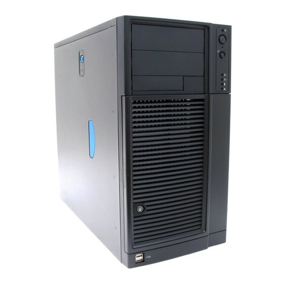
Page 21: Component Identification
Front View Components TP02345 A. 5.25-in Device Drive Bays B. Front Panel C. Drive Bay Access Door D. Door Lock E. Front Panel USB Ports Figure 2. Front View Components (with Front Bezel Assembly) ® Intel Server Chassis SC5650-DP/WS/BRP/UP Service Guide... -
Page 22: Figure 3. Front View Components (Without Front Bezel Assembly)
A. 5.25-in Device Drive Bays B. 3.5-in Device Drive Bay C. Hard Drive Cage D. Drive Bay EMI Shield (shown open) E. Front Panel USB Ports Figure 3. Front View Components (without Front Bezel Assembly) ® Intel Server Chassis SC5650-DP/WS/BRP/UP Service Guide... -
Page 23: Internal Components
F. PCI Add-in Card Guide G. Front Panel USB Ports H. Rear Tool-less PCI Retention Mechanisms I. Fan Duct / System Fan Assembly J. Power Supply Figure 4. Internal Components (DP/WS/BRP Configuration Shown) ® Intel Server Chassis SC5650-DP/WS/BRP/UP Service Guide... -
Page 24: Back Panel Components
Server Chassis Features Back Panel Components ® Intel Server Chassis SC5650-DP/WS/BRP/UP Service Guide... -
Page 25: Front Panel
F. System Fan G. Serial B port knockout (UP only) H. Location to install padlock Loop I. External SCSI knockout J. Alternate Serial B port knockout Figure 5. Back Panel Components Front Panel TP02346 ® Intel Server Chassis SC5650-DP/WS/BRP/UP Service Guide... -
Page 26: Peripheral Devices
The server chassis provides locations and hardware for installing hard drives, a floppy drive, CD-ROM drive, DVD-ROM drive, or tape drive. You must purchase the drives separately. The following figure shows the available options. ® Intel Server Chassis SC5650-DP/WS/BRP/UP Service Guide... -
Page 27: Hard Disk Drives
(capable of handling up to six hot-swappable, SATA or SAS hard drives) to replace the fixed hard drive cage. See Table 3 for order code information. For instructions on installing hard drives, see “Installing and Removing a Fixed Hard Drive”. ® Intel Server Chassis SC5650-DP/WS/BRP/UP Service Guide... -
Page 28: Front Bezel Assembly
Server Chassis SC5650 can be optionally mounted into a rack. Instructions for installing your chassis into a rack are included with the rail kit. The order number for the rack mounting kit is APP3RACKIT. ® Intel Server Chassis SC5650-DP/WS/BRP/UP Service Guide... -
Page 29: Mechanical Locks
AXX6DRV3GR Assembly Cage Kit Hot-Swap Drive Cooling and Mounting Kit APPTHSDBKIT Hot Swap Conversion Kit APP3HSDBKIT Rack Mount Kit APP3RACKIT Note: AXX6DRV3GEXP should be used with APP3HSDBKIT; AXX6DRV3GR should be used with APPTHSDBKIT. ® Intel Server Chassis SC5650-DP/WS/BRP/UP Service Guide... - Page 30 Server Chassis Features ® Intel Server Chassis SC5650-DP/WS/BRP/UP Service Guide...
-
Page 31: Hardware Installations And Upgrades
1. Observe the safety and ESD precautions listed in Appendix A, “Safety Information”. 2. Turn off all peripheral devices connected to the server. Turn off the server. 3. Disconnect the AC power cord(s). ® Intel Chassis SC5650-DP/WS/BRP/UP Service Guide... -
Page 32: Installing The Left Side Cover
1. Slide the left side cover on the chassis and latch securely (see letter “A” in the following figure). 2. (Optional) Replace screws (see letter “B”). TP00831 Figure 10. Installing Left Side Cover 3. Reconnect all peripheral devices and the AC power cord. Power up the server. ® Intel Chassis SC5650-DP/WS/BRP/UP Service Guide... -
Page 33: Removing And Installing The Right Side Cover
5. Remove the two screws (see letter “A” in the following figure”) securing the right side cover to the chassis. Lift the right side cover off the chassis. TP01736 Figure 11. Removing Right Side Cover from Chassis ® Intel Chassis SC5650-DP/WS/BRP/UP Service Guide... -
Page 34: Installing The Right Side Cover
2. Reinstall the front bezel assembly. For instructions, see “Installing the Front Bezel Assembly”. 3. Reinstall the left side cover. For instructions, see “Installing the Left Side Cover” 4. Reconnect all peripheral devices and the AC power cable. Power up the server. ® Intel Chassis SC5650-DP/WS/BRP/UP Service Guide... -
Page 35: Removing And Installing The Front Bezel Assembly
Hardware Installations and Upgrades Removing and Installing the Front Bezel Assembly ® All configurations of the Intel Server Chassis SC5650 ship with a two-piece front bezel assembly. Removing the Front Bezel Assembly 1. Observe the safety and ESD precautions listed in Appendix A, “Safety... -
Page 36: Installing The Front Bezel Assembly
Server Board you can install in your chassis depends on the model of chassis you purchased. For a breakout of server board/chassis model compatibility, see Table 1, “Breakdown of Intel® Server Chassis SC5650 Configurations”. To install or remove a server board, do the following: 1. -
Page 37: Figure 15. Removing Drive Cage Emi Shield From Fixed Drive Cage (Dp/Ws/Brp Configuration Shown)
6. Disconnect cables from any installed fixed hard drives. If necessary, remove hard drives from fixed hard drive cage. For instructions on removing fixed hard drives, see “Removing a Fixed Hard Drive”. ® Intel Chassis SC5650-DP/WS/BRP/UP Service Guide... -
Page 38: Figure 16. Removing Fixed Hard Drive Cage (Dp/Ws/Brp Configuration Shown)
Server Board SC5500BC Only: Remove the PCI card guide by pressing in on the blue tabs (see letter “A” in the following figure) and pulling the PCI card guide outward (see letter “B”). TP01732 Figure 17. Removing PCI Card Guide ® Intel Chassis SC5650-DP/WS/BRP/UP Service Guide... -
Page 39: Figure 18. Re-Installing Pci Card Guide Into Chassis
Hardware Installations and Upgrades ® 10. If installing a server board, refer to your Intel Server Board User’s Guide and/or Quick Start User’s Guide for installation instructions. Use the mounting screws, bumpers and standoffs (if necessary) that came with your chassis to secure the server board to the chassis. -
Page 40: Figure 19. Inserting Fixed Hard Drive Cage Into Chassis (Dp/Ws/Brp Configuration Only)
Figure 19. Inserting Fixed Hard Drive Cage into Chassis (DP/WS/BRP configuration only) 13. If previously removed, install fixed hard drives and connect power and data cables. For instructions, see “Installing a Fixed Hard Drive”. ® Intel Chassis SC5650-DP/WS/BRP/UP Service Guide... -
Page 41: Figure 20. Re-Attaching Drive Cage Emi Shield
Front Bezel Assembly” 16. Re-install the left side cover. For instructions, see “Installing the Left Side Cover” 17. Plug all peripheral devices and the AC power cable(s) back into the server. Power up the server. ® Intel Chassis SC5650-DP/WS/BRP/UP Service Guide... -
Page 42: Installing And Removing A Fixed Hard Drive
Figure 21. Drive Bay Slot Order 1. Observe the safety and ESD precautions listed in Appendix A, “Safety Information”. 2. Power down the server and unplug all peripheral devices and the AC power cable. ® Intel Chassis SC5650-DP/WS/BRP/UP Service Guide... -
Page 43: Figure 22. Removing Drive Cage Emi Shield From Chassis (Dp/Ws/Brp Configuration Shown)
TP01869 Figure 22. Removing Drive Cage EMI Shield from Chassis (DP/WS/BRP configuration shown) 6. Remove any PCI add-in boards that use the PCI card guide. For instructions, see “Removing PCI Add-in Boards”. ® Intel Chassis SC5650-DP/WS/BRP/UP Service Guide... -
Page 44: Figure 23. Removing Pci Card Guide
8. Route the required power cables (connectors P7-P10 for DP/BRP/WS, P6-P8 and P10-P12 for UP) from behind the PCI card guide through the cable routing area at the bottom of the fixed drive cage. AF000317 Figure 24. Routing Hard Drive Power Cables ® Intel Chassis SC5650-DP/WS/BRP/UP Service Guide... -
Page 45: Figure 25. Unlatching Drive Latch
10. Insert fixed hard drive into drive bay and push until it stops. Ensure the power and data connector end of the hard drive are facing forward. AF000319 Figure 26. Inserting Hard Drive into Drive Cage ® Intel Chassis SC5650-DP/WS/BRP/UP Service Guide... -
Page 46: Figure 27. Latching Drive Latch
12. Install additional drives as necessary. Warning: You MUST populate drive bay slots 1, 3, and 5 first. Failure to do so could result in thermal issues within the chassis. AF000316 Figure 28. Drive Bay Slot Order ® Intel Chassis SC5650-DP/WS/BRP/UP Service Guide... -
Page 47: Figure 29. Cabling A Fixed Hard Drive
AF000429 Figure 29. Cabling a Fixed Hard Drive 14. Re-attach the drive cage EMI shield to the chassis and tighten the thumb screw. AF000315 Figure 30. Re-installing Drive Cage EMI Shield ® Intel Chassis SC5650-DP/WS/BRP/UP Service Guide... -
Page 48: Removing A Fixed Hard Drive
2. Power down the server and unplug all peripheral devices and the AC power cable. 3. Remove the left side cover. For instructions, see “Removing the Left Side Cover”. 4. Remove the front bezel assembly. For instructions, see “Removing and Installing the Front Bezel Assembly”. ® Intel Chassis SC5650-DP/WS/BRP/UP Service Guide... -
Page 49: Figure 32. Removing Drive Cage Emi Shield From Chassis (Dp/Ws/Brp Configuration Shown)
“A” in the following figure). Pull the drive latch forward (see letter “B”) to unlatch the drive-locking mechanism for the hard drive you want to remove. AF000430 Figure 33. Preparing Fixed Hard Drive for Removal ® Intel Chassis SC5650-DP/WS/BRP/UP Service Guide... -
Page 50: Figure 34. Removing Fixed Hard Drive From Drive Bay
Figure 35. Re-installing Drive Cage EMI Shield 9. Re-install the front bezel assembly. For instructions, see “Installing the Front Bezel Assembly”. 10. Re-install the left side cover. For instructions, see “Installing the Left Side Cover”. ® Intel Chassis SC5650-DP/WS/BRP/UP Service Guide... -
Page 51: Installing Or Removing A Dvd-Rom Or Cd-Rom Drive
5. Remove the EMI shield from the 5.25-in device drive bay (see letter “A” in the following figure). Move latch to the “unlock” position (see letter “B”). TP01063 Figure 36. Removing 5.25-in Drive EMI Shield (DP/WS/BRP configuration shown) ® Intel Chassis SC5650-DP/WS/BRP/UP Service Guide... -
Page 52: Figure 37. Installing Cd-Rom Or Dvd-Rom Drive (Dp/Ws/Brp Configuration Shown)
4-pin power connector.) and data cables to the rear of the CD-ROM or DVD- ROM drive (see letter “F”). Figure 37. Installing CD-ROM or DVD-ROM Drive (DP/WS/BRP configuration shown) 7. If necessary, remove the filler panel from the front bezel assembly. TP01723 ® Intel Chassis SC5650-DP/WS/BRP/UP Service Guide... -
Page 53: Removing A Cd-Rom Or Dvd-Rom Drive
(see letter “F” in the following figure). Move latch to the “unlock” position (see letter “D”). Slide CD-ROM or DVD-ROM drive out of the Device Drive Bay (see letter “C”). AF003105 Figure 38. Removing CD-ROM or DVD-ROM Drive (DP/WS/BRP configuration shown) ® Intel Chassis SC5650-DP/WS/BRP/UP Service Guide... -
Page 54: Installing And Removing Pci Add-In Boards
Note: Before installing any PCI add-in boards, you may want to install an operating system. 1. Observe the safety and ESD precautions listed in Appendix A, “Safety Information”. 2. Power down the server and unplug all peripheral devices and the AC power cable. ® Intel Chassis SC5650-DP/WS/BRP/UP Service Guide... -
Page 55: Figure 40. Opening Pci Add-In Card Retention Device (Dp/Ws/Brp Configuration Shown)
Place the board on an anti-static surface. Record the type and serial number of the add-in board in your equipment log. Set jumpers or switches on the board according to the manufacturer’s instructions. ® Intel Chassis SC5650-DP/WS/BRP/UP Service Guide... -
Page 56: Removing Pci Add-In Boards
1. Observe the safety and ESD precautions listed in Appendix A, “Safety Information”. 2. Power down the server and unplug all peripheral devices and the AC power cable. 3. Remove the left side cover. For instructions, see “Removing the Left Side Cover”. ® Intel Chassis SC5650-DP/WS/BRP/UP Service Guide... -
Page 57: Figure 43. Opening Pci Add-In Card Retention Device (Dp/Ws/Brp Configuration Shown)
(see letter “A” in the following figure). Place the removed add-in board in an anti-static protective wrapper. Close the back panel PCI Add-in Card Retention Device (see letter “B”). TP01724 Figure 44. Removing PCI Add-in Board ® Intel Chassis SC5650-DP/WS/BRP/UP Service Guide... -
Page 58: Replacing The Front Panel Board
2. Power down the server and unplug all peripheral devices and the AC power cable. 3. Remove the left side cover. For instructions, see “Removing the Left Side Cover”. 4. Remove the front bezel assembly if it is installed. For instructions, see “Removing the Front Bezel Assembly”. ® Intel Chassis SC5650-DP/WS/BRP/UP Service Guide... -
Page 59: Figure 46. Removing Right Side Cover From Chassis
Lift the right side cover off the chassis. TP01736 Figure 46. Removing Right Side Cover from Chassis 6. Remove the three screws securing the front panel board to the chassis. TP01737 Figure 47. Unattaching Front Panel Board from Chassis ® Intel Chassis SC5650-DP/WS/BRP/UP Service Guide... -
Page 60: Figure 48. Removing Front Panel Board From Chassis
“B”) and the chassis intrusion cable (see letter “C”) from the front panel board. AF000432 Figure 48. Removing Front Panel Board from Chassis 8. Remove standoffs from the old front panel and install on the new front panel. TP02000 Figure 49. Removing Standoffs from Front Panel ® Intel Chassis SC5650-DP/WS/BRP/UP Service Guide... -
Page 61: Figure 50. Installing Front Panel Board In Chassis
10. Use one hand to align the front panel board in position inside the chassis. With your other hand, tighten the three screws to secure the front panel board to the front of the chassis. TP01740 Figure 51. Positioning Front Panel Board in Chassis ® Intel Chassis SC5650-DP/WS/BRP/UP Service Guide... -
Page 62: Replacing A System Fan
14. Reconnect all peripheral devices and the AC power cable. Power up the server. Replacing a System Fan ® Caution: The system fan for the Intel Server Chassis SC5650 is NOT hot swappable. Before removing or replacing a fan, you must first take the server out of service, turn off all peripheral devices connected to the system, turn off the system by pressing the power button, and unplug the AC power cord from the system or wall outlet. -
Page 63: Figure 53. Removing Fan Duct / System Fan Assembly (Dp/Ws/Brp Configuration)
Hardware Installations and Upgrades ® 4. (For all server boards on DP/WS/BRP configuration EXCEPT Intel Server Board S5500BC) Remove the fan duct /system fan assembly. Figure 53. Removing Fan Duct / System Fan Assembly (DP/WS/BRP configuration) 5. Disconnect the fan power cable from the server board (see letter “A” in the following figure). -
Page 64: Figure 55. Removing Fan Duct / System Fan Assembly (Up Configuration)
Figure 56. Installing System Fan in Chassis ® 8. (For all server boards on DP/WS/BRP configuration EXCEPT Intel Server Board S5500BC) Re-install the fan duct / system fan assembly. -
Page 65: Figure 57. Re-Installing Fan Duct / System Fan Assembly (Dp/Ws/Brp Configuration)
11. Install the left side cover. For instructions, see “Installing the Left Side Cover”. 12. Plug all peripheral devices and the AC power cable into the server. Power up the server. ® Intel Chassis SC5650-DP/WS/BRP/UP Service Guide... -
Page 66: Replacing A Fixed Power Supply
® Caution: The fixed power supply is NOT hot-swappable in the DP, UP, and WS models of the Intel Server Chassis SC5650. Before removing or replacing the fixed power supply, you must... -
Page 67: Figure 60. Removing Fixed Power Supply From Chassis
Make sure the new fixed power supply rests on the small metal shelf on the side wall of the chassis (see letter “A” in the following figure). TP01753 Figure 61. Inserting Fixed Power Supply in Chassis ® Intel Chassis SC5650-DP/WS/BRP/UP Service Guide... -
Page 68: Figure 62. Locking Fixed Power Supply Into Chassis
Figure 62. Locking Fixed Power Supply into Chassis 9. Route and connect the P1, P2, P3 and P4 (for DP/BRP/WS), P1 and P2 (for UP)cables ® to the server board. Refer to the Intel Server Board Quick Start User’s Guide or User ®... -
Page 69: Installing An Additional Hot Swap Power Supply Module (Brp Configuration Only)
2. Insert finger into hole in middle of filler panel and remove filler panel from chassis. AF002947 Figure 63. Removing Power Supply Filler Panel 3. Insert new hot swap power supply module until it clicks into place. Figure 64. Inserting Additional Hot Swap Power Supply Module ® Intel Chassis SC5650-DP/WS/BRP/UP Service Guide... -
Page 70: Removing A Hot Swap Power Supply (Brp Configuration Only)
3. Press up on green latch (see letter “A” in the following figure) while pulling on handle (see letter “B”) to remove hot swap power supply from chassis. Figure 65. Removing Hot Swap Power Supply Module from Chassis 4. Insert new hot swap power supply module. ® Intel Chassis SC5650-DP/WS/BRP/UP Service Guide... -
Page 71: Replacing A Hot Swap Power Supply Cage (Brp Configuration Only)
3. Remove the left side cover. For instructions, see “Removing the Left Side Cover”. 4. Press up on green latch (see letter “A”) while pulling on handle to remove hot swap power supply module from chassis. ® Intel Chassis SC5650-DP/WS/BRP/UP Service Guide... -
Page 72: Figure 67. Removing Hot Swap Power Supply Module
Figure 68. Detaching Hot Swap Power Supply Cage from Inside of Chassis 8. Remove five external screws securing back of power supply cage to chassis. Slide the power supply cage out of the chassis. ® Intel Chassis SC5650-DP/WS/BRP/UP Service Guide... -
Page 73: Figure 69. Detaching Hot Swap Power Supply Cage From Rear Of Chassis
“B”). Figure 70. Removing Rear Support Bracket from Hot Swap Power Supply Cage 10. Attach the rear support bracket to the new power supply cage with the two screws removed from the previous step. ® Intel Chassis SC5650-DP/WS/BRP/UP Service Guide... -
Page 74: Figure 71. Attaching Rear Support Bracket To Power Supply Cage
TP01766 Figure 72. Securing Hot Swap Power Supply Cage to Rear of Chassis 12. Secure the inside panel of the hot swap power supply cage to chassis with two screws. ® Intel Chassis SC5650-DP/WS/BRP/UP Service Guide... -
Page 75: Figure 73. Securing Hot Swap Power Supply Cage To Inside Of Chassis
16. Route the P11, P12, P13, and P14 cables to the hard drive cage and connect power cables to installed devices. 17. Reinstall the hot swap power supply module(s). The power supply module(s) clicks into place when properly seated. ® Intel Chassis SC5650-DP/WS/BRP/UP Service Guide... -
Page 76: Figure 74. Re-Installing Hot Swap Power Supply Module(S)
Figure 74. Re-installing Hot Swap Power Supply Module(s) 18. Install the left side cover. For instructions, see “Installing the Left Side Cover”. 19. Reconnect all peripheral devices and the AC power cable(s) to the server. Power up the server. ® Intel Chassis SC5650-DP/WS/BRP/UP Service Guide... -
Page 77: Installing Feet For A Pedestal-Configured Chassis
Hardware Installations and Upgrades Installing Feet for a Pedestal-configured Chassis ® Note: Do not install feet on your Intel Server Chassis SC5650 if it is to be installed in a rack. Only install feet on a pedestal-configured chassis. 1. Observe the safety and ESD precautions listed in Appendix A, “Safety... - Page 78 Hardware Installations and Upgrades ® Intel Chassis SC5650-DP/WS/BRP/UP Service Guide...
-
Page 79: Hot Swap Drive Cage Upgrade Install Instructions (Optional)
The fixed hard drive cage that ships with your Intel Server Chassis SC5650 is upgradeable to a hot swap drive cage with a SAS/SATA backplane. See your Intel Representative for ordering information. You can install up to six hot swap hard drives in the optional hot swap drive cage. Power requirements for each individual hard drive may limit the maximum number of drives that can be integrated into the server chassis. -
Page 80: Installing A Hot Swap Hard Drive Cage With A Sas/Sata Backplane
BRP configuration shown) 6. Disconnect cables from any fixed hard drives and remove hard drives from the fixed hard drive cage. For instructions on removing fixed hard drives, see “Removing a Fixed Hard Drive”. ® Intel Server Chassis SC5650-DP/WS/BRP/UP Service Guide... -
Page 81: Figure 77. Removing Fixed Hard Drive Cage From Chassis (Dp/Ws/Brp Configuration Shown)
8. Gather together the components for the hot swap drive cage installation. You should have a hot swap drive cage with a SAS/SATA backplane, a side filler panel, a latch plate, a fan bracket, and a fan. ® Intel Server Chassis SC5650-DP/WS/BRP/UP Service Guide... -
Page 82: Figure 78. Removing Stud Screws From Hot Swap Drive Cage
Figure 78. Removing Stud Screws from Hot Swap Drive Cage 10. Attach the latch plate to the left side of the hot swap drive cage. TP01060 Figure 79. Attaching Latch Plate to Hot Swap Drive Cage ® Intel Server Chassis SC5650-DP/WS/BRP/UP Service Guide... -
Page 83: Figure 80. Attaching Filler Panel To Hot Swap Drive Cage
Figure 80. Attaching Filler Panel to Hot Swap Drive Cage 12. Remove the two thumb screws that secure the backplane to the hot swap drive cage. AF002936 Figure 81. Removing Thumb Screws from Backplane ® Intel Server Chassis SC5650-DP/WS/BRP/UP Service Guide... -
Page 84: Figure 82. Attaching Fan Bracket To Expanded Hot Swap Drive Cage
The backplane may have slipped once the thumb screws were removed. Ensure the backplane is positioned correctly before re-tightening the thumb screws. AF002937 Figure 82. Attaching Fan Bracket to Expanded Hot Swap Drive Cage ® Intel Server Chassis SC5650-DP/WS/BRP/UP Service Guide... -
Page 85: Figure 83. Attaching Fan Bracket To Non-Expanded Hot Swap Drive Cage
Hot Swap Drive Cage Upgrade Install Instructions (optional) AF003066 Figure 83. Attaching Fan Bracket to Non-Expanded Hot Swap Drive Cage ® Intel Server Chassis SC5650-DP/WS/BRP/UP Service Guide... -
Page 86: Figure 84. Attaching Fan To Fan Bracket
Press the fan into the fan bracket until it clicks into place. Caution: Ensure the label and directional airflow arrow on fan are pointed out (away from the backplane). AF002940 Figure 84. Attaching Fan to Fan Bracket ® Intel Server Chassis SC5650-DP/WS/BRP/UP Service Guide... -
Page 87: Figure 85. Attaching Fan To Fan Bracket Non-Expanded, Hot Swap Drive Cage
Hot Swap Drive Cage Upgrade Install Instructions (optional) AF003067 Figure 85. Attaching Fan to Fan Bracket Non-Expanded, Hot Swap Drive Cage ® Intel Server Chassis SC5650-DP/WS/BRP/UP Service Guide... -
Page 88: Figure 86. Inserting Hot Swap Drive Cage Into Chassis (Dp/Ws/Brp Configuration Shown)
Figure 86. Inserting Hot Swap Drive Cage into Chassis (DP/WS/BRP configuration shown) 16. Connect the fan cable to the appropriate connector on the server board. See your server board documentation for information on the location of the fan cable connector. ® Intel Server Chassis SC5650-DP/WS/BRP/UP Service Guide... - Page 89 SAS/SATA backplane to your server board or RAID Controller card. Failure to do so may result in data loss. Note: The SAS/SATA cables are labeled to correspond with each drive. Make sure to connect the cables correctly to avoid confusion later. ® Intel Server Chassis SC5650-DP/WS/BRP/UP Service Guide...
-
Page 90: Figure 87. Layout Of Cable Connectors On The Sas/Sata Backplane (Backplane Without Expander Shown)
The SAS/SATA connectors are laid out as follows on the SAS/SATA backplane. SATA/SAS hot-swap drive connectors SATA/SAS cable connectors SES header SGPIO header IPMB header Power connectors Figure 87. Layout of Cable Connectors on the SAS/SATA Backplane (Backplane without expander shown) ® Intel Server Chassis SC5650-DP/WS/BRP/UP Service Guide... -
Page 91: Figure 88. Making Six-Drive Sas/Sata Hot-Swap Drive Cage Backplane Without Expander Connections (Dp/Ws/Brp Configuration Shown - Fan Bracket Not Shown In The Illustration For Clarity)
Connect the SES cable (see letter “D”). v. Connect the fan power to the server board. ® vi. Connect the IPMB cable (see letter “E”). For other Intel server boards, refer to the Quick Start User’s Guide that came with the server board. -
Page 92: Figure 89. Making Six-Drive Hot Swap Drive Cage Backplane With Expander Connections (Dp/Ws/Brp Configuration Shown - Fan Bracket Not Shown In The Illustration For Clarity)
SATA connector on the SAS/SATA backplane. iii. Connect the IPMB cable (see letter “C”). ® iv. Connect the fan power to the server board. For other Intel server boards, refer to the Quick Start User’s Guide that came with the server board. -
Page 93: Installing A Hot Swap Hard Drive
Server Chassis SC5650 does not support all hard drives. See “Additional Information and Software”for an Internet link to a list of supported hard drives. 1. Open the drive bay access door. AF000311 Figure 90. Opening Drive Bay Access Door ® Intel Server Chassis SC5650-DP/WS/BRP/UP Service Guide... -
Page 94: Figure 91. Releasing Drive Carrier From Hot Swap Drive Cage
5. Set any jumpers and/or switches on the drive according to the drive manufacturer's instructions. 6. With the drive circuit-side down, position the connector end of the drive so that it is facing the rear of the drive carrier. ® Intel Server Chassis SC5650-DP/WS/BRP/UP Service Guide... -
Page 95: Figure 93. Installing Hard Drive Into Drive Carrier
Once the black drive carrier lever begins to close by itself, push on it to lock the drive carrier into place. AF000313 Figure 94. Re-installing Drive Carrier in Hot Swap Drive Cage ® Intel Server Chassis SC5650-DP/WS/BRP/UP Service Guide... -
Page 96: Removing A Hot-Swap Hard Drive
9. Close the drive bay access door. AF000314 Figure 95. Closing Drive Bay Access Door Removing a Hot-swap Hard Drive 1. Open the drive bay access door. AF000311 Figure 96. Opening Drive Bay Access Door ® Intel Server Chassis SC5650-DP/WS/BRP/UP Service Guide... -
Page 97: Figure 97. Removing Drive Carrier From Hot Swap Drive Cage
3. Remove the four screws that attach the hard drive to the drive carrier. Lift the drive from the carrier. Store the old drive in an anti-static bag. TP01714 Figure 98. Removing Hard Drive from Drive Carrier ® Intel Server Chassis SC5650-DP/WS/BRP/UP Service Guide... -
Page 98: Figure 99. Installing Hard Drive In Drive Carrier
The green latch must be to the left. Do not push on the black lever until the lever begins to close by itself. When the black lever begins to close by itself, push on it to lock the drive carrier into place. ® Intel Server Chassis SC5650-DP/WS/BRP/UP Service Guide... -
Page 99: Figure 101. Re-Installing Drive Carrier In Hot Swap Drive Cage
Note: For proper airflow, the drive carrier must be replaced in the chassis, even if no hard drive is installed in it. AF000313 Figure 101. Re-installing Drive Carrier in Hot Swap Drive Cage 6. Close the drive bay access door. AF000314 Figure 102. Closing Drive Bay Access Door ® Intel Server Chassis SC5650-DP/WS/BRP/UP Service Guide... - Page 100 Hot Swap Drive Cage Upgrade Install Instructions (optional) ® Intel Server Chassis SC5650-DP/WS/BRP/UP Service Guide...
-
Page 101: Rack Mount Kit Install Instructions (Optional)
1. Observe the safety and ESD precautions listed in Appendix A, “Safety Information”. 2. Power down the server and unplug all peripheral devices and the AC power cable. 3. Lay the chassis down on its right side. ® Intel Server Chassis SC5650-DP/WS/BRP/UP Service Guide... -
Page 102: Figure 103. Removing Chassis Feet
5. Remove the top side cover by pressing the latch and pushing back on the side cover to slide rearward and lift from chassis. TP00958 Figure 104. Removing Top Side Cover from Chassis ® Intel Server Chassis SC5650-DP/WS/BRP/UP Service Guide... -
Page 103: Figure 105. Removing Pci Card Guide
6. Remove any PCI add-in boards. Remove the PCI card guide by pressing in on the blue tabs (see letter “A” in the following figure) and pulling the PCI card guide outward (see letter “B”). TP02001 Figure 105. Removing PCI Card Guide ® Intel Server Chassis SC5650-DP/WS/BRP/UP Service Guide... -
Page 104: Figure 106. Removing Plastic Filler Panel From Chassis (Dp/Ws/Brp Configuration Shown)
7. Remove plastic filler panel from chassis by pushing on interior tab (see letter “A” in the following figure) and sliding filler panel towards rear of chassis (see letter “B”). AF000285 Figure 106. Removing Plastic Filler Panel from Chassis (DP/WS/BRP configuration shown) ® Intel Server Chassis SC5650-DP/WS/BRP/UP Service Guide... -
Page 105: Figure 107. Removing Plastic Plugs (Dp/Ws/Brp Configuration Shown)
8. Remove the three plastic plugs from the left side of chassis. AF000286 Figure 107. Removing Plastic Plugs (DP/WS/BRP configuration shown) 9. Remove two screws from the left and right sides of chassis. AF000287 Figure 108. Removing Rear Screws (DP/WS/BRP configuration shown) ® Intel Server Chassis SC5650-DP/WS/BRP/UP Service Guide... -
Page 106: Figure 109. Removing Plastic Plugs From Top Side Cover
10. Remove the four plastic plugs from the top side cover. TP02004 Figure 109. Removing Plastic Plugs from Top Side Cover 11. Install rack handle on left side cover using four 6-32 screws. TP01053 Figure 110. Installing Rack Handle on Left Side Cover ® Intel Server Chassis SC5650-DP/WS/BRP/UP Service Guide... -
Page 107: Figure 111. Affixing Label To Front Panel
Figure 111. Affixing Label to Front Panel 13. Install top side cover on chassis. Warning: This chassis must be operated with the left side cover installed to ensure proper cooling. TP01057 Figure 112. Installing Top Side Cover on Chassis ® Intel Server Chassis SC5650-DP/WS/BRP/UP Service Guide... -
Page 108: Figure 113. Detaching Inner Rack Rail From Rack Rail Assembly
14. Detach inner rack rail from rack rail assembly. Press tab on inside of rack rail to release rack rail from rack rail assembly. TP02006 Figure 113. Detaching Inner Rack Rail from Rack Rail Assembly ® Intel Server Chassis SC5650-DP/WS/BRP/UP Service Guide... -
Page 109: Figure 114. Attaching Inner Rack Rails To Chassis (Dp/Ws/Brp Configuration Shown)
16. Attach outer rack rails to rack uprights. Ensure the screws (two per outer rack rail; see letter “A” in the following figure) pass through the rack upright (see letter “B”), and the outer rack rail (see letter “C”). ® Intel Server Chassis SC5650-DP/WS/BRP/UP Service Guide... -
Page 110: Figure 115. Attaching Outer Rack Rails To Rack Uprights
Rack Mount Kit Install Instructions (optional) TP01056 Figure 115. Attaching Outer Rack Rails to Rack Uprights ® Intel Server Chassis SC5650-DP/WS/BRP/UP Service Guide... -
Page 111: Figure 116. Installing Chassis Into Rack
WARNING: Safe handling of this system requires TWO people. TP01058 Figure 116. Installing Chassis into Rack 18. Reconnect all peripheral devices and the AC power cable to the server. Power up the server. ® Intel Server Chassis SC5650-DP/WS/BRP/UP Service Guide... - Page 112 Rack Mount Kit Install Instructions (optional) ® Intel Server Chassis SC5650-DP/WS/BRP/UP Service Guide...
-
Page 113: Technical Reference
Server Chassis SC5650 depend upon the configuration of chassis you purchased. Three power supply configurations are available: • 600-W PFC Intel validated PSU (power supply unit) with integrated cooling fan (DP configuration) • 600-W PFC Intel validated PSU with integrated cooling fan. You can add one additional 600-W PSU for redundancy. -
Page 114: 600-W Single Power Supply Input Voltages
16 A +12 V4 16 A -12.0 V 0.5 A DP 400-W Power Supply Input Voltages • 100-127 V at 50/60 Hz; 5.8 A max. • 200-240 V at 50/60 Hz; 2.9 A max. ® Intel Server Chassis SC5650-DP/WS/BRP/UP Service Guide... -
Page 115: Dp 400-W Power Supply Output Voltages
DP, BRP configurations - 5.5 BA LWA idle; 6.0 BA LWA typical operation WS configuration - 4.8 BA LWA idle; 5.5 BA LWA typical operation Electrostatic Air Discharge: 0 to 12.0 kV discharge (ESD) Contact Discharge: 0 to 8.0kV ® Intel Server Chassis SC5650-DP/WS/BRP/UP Service Guide... - Page 116 Technical Reference ® Intel Server Chassis SC5650-DP/WS/BRP/UP Service Guide...
-
Page 117: Safety Information
Indicates the presence of a hazard that may result in serious personal injury if WARNING the WARNING is ignored. Indicates potential hazard if indicated information is ignored. Indicates shock hazards that result in serious injury or death if safety instructions are not followed. Intel® Server Chassis SC5650-DP/WS/BRP/UP Service Guide... -
Page 118: Intended Application Uses
Provided with sufficient space to access the power supply cord(s), because they serve as the product's main power disconnect. Equipment Handling Practices Reduce the risk of personal injury or equipment damage: • Conform to local occupational health and safety requirements when moving and lifting equipment. Intel® Server Chassis SC5650-DP/WS/BRP/UP Service Guide... -
Page 119: Power And Electrical Warnings
Do not access the inside of the power supply. There are no serviceable parts in the power supply. Return to manufacturer for servicing. • Power down the chassis and disconnect all power cords before adding or replacing any non hot-plug component. Intel® Server Chassis SC5650-DP/WS/BRP/UP Service Guide... -
Page 120: Electrostatic Discharge (Esd)
Check first to make sure you have not left loose tools or parts inside the chassis • Check that cables, add-in boards, and other components are properly installed. • Attach the covers to the chassis according to the product instructions. Intel® Server Chassis SC5650-DP/WS/BRP/UP Service Guide... -
Page 121: Deutsch
Return to manufacturer for servicing Deutsch Sicherheitshinweise für den Server ® ® Das vorliegende Dokument bezieht sich auf Intel Serverplatinen, Intel Servergehäuse (Standfuß und Rack) sowie installierte Peripheriegeräte. Es enthält Warnungen und Vorsichtsmaßnahmen zur Vermeidung von Gefahren durch Verletzung, Stromschlag, Feuer und Beschädigungen von Geräten. -
Page 122: Zielbenutzer Der Anwendung
Überspannungsschutz anschließen und bei einem Gewitter die Telekommunikationskabel zum Modem abziehen. • Eine ordnungsgemäß geerdete Wandsteckdose muß vorhanden sein. • Ausreichender Freiraum für den Zugang zu den Netzkabeln, da diese die Hauptvorrichtung zum Trennen des Produkts von der Stromversorgung sind. Intel® Server Chassis SC5650-DP/WS/BRP/UP Service Guide... -
Page 123: Handhabung Von Geräten
• Verwenden Sie mechanische oder andere geeignete Hilfsmittel zum Transportieren oder Anheben von Geräten. • Entfernen Sie alle Komponenten, die sich leicht abnehmen lassen, um das Gewicht zu reduzieren und die Handhabung zu erleichtern. Intel® Server Chassis SC5650-DP/WS/BRP/UP Service Guide... -
Page 124: Warnungen Zu Netzspannung Und Elektrizität
Typ entspricht. Jedes Netzteil im System muß über ein eigenes Netzkabel angeschlossen werden. Einige Netzteile von Intel Servern verwenden Nullleitersicherungen. Vorsicht ist geboten im Umgang mit Netzteilen, welche Nullleitersicherungen verwenden, um das Risiko eines elektrischen Schlages zu vermeiden Das Netzteil in diesem Produkt enthält keine Teile, die vom Benutzer gewartet werden... -
Page 125: Elektrostatische Entladungen (Esd)
Ausbau aus dem Server mit der Bauelementseite nach oben auf eine geerdete, statisch entladene Unterlage.Verwenden Sie dazu, sofern verfügbar, eine leitfahige Schaumstoffunterlage, aber niche die Schutzhülle der Platine. Ziehen Sie die Platine nicht über eine Fläche. Intel® Server Chassis SC5650-DP/WS/BRP/UP Service Guide... -
Page 126: Andere Gefahren
Vorsicht: Beachten Sie zur Vermeidung von Strahlung und Verletzungen die folgenden Hinweise: • Öffnen Sie keinesfalls das Gehäuse von Laser-Peripheriegeräten oder Laser- Komponenten. • Laser-Peripheriegeräte oder -Komponenten besitzen keine für den Benutzer wartungsbedürftigen Teile. • Schicken Sie das Gerät für Wartungsarbeiten an den Hersteller zurück. Intel® Server Chassis SC5650-DP/WS/BRP/UP Service Guide... -
Page 127: Français
® d’installer ou de mettre à jour votre produit serveur Intel En cas de conflit entre les informations fournies dans ce document et celles livrées avec le produit ou publiées sur le site Web pour un produit particulier, la documentation du produit prime. -
Page 128: Domaines D'utilisation Prévus
• Utilisez l’assistance mécanique ou toute autre assistance appropriée lorsque vous déplacez et soulevez le matériel. • Pour réduire le poids en vue de faciliter la manipulation, retirez tout composant amovible. Intel® Server Chassis SC5650-DP/WS/BRP/UP Service Guide... -
Page 129: Alimentation Et Avertissements En Matière D'électricité
Vous devez les débrancher avant d’ouvrir le châssis, d’ajouter ou de supprimer un composant non connectable à chaud. Les alimentations de certains serveurs Intel sont munies de doubles fusibles pôle/neutre: veuillez observer les précautions d'usage afin d'éviter tout risque d'eléctrocution. -
Page 130: Décharges Électrostatiques (Esd)
Afin de permettre une ventilation et un refroidissement corrects, ne mettez le système en marche que lorsque les panneaux du châssis sont en place. L’utilisation du système sans les panneaux peut endommager les composants système. Pour installer les panneaux : Intel® Server Chassis SC5650-DP/WS/BRP/UP Service Guide... -
Page 131: Español
Retournez-les au fabricant en cas de problème. Español Información de seguridad del servidor ® Este documento se aplica a las tarjetas de servidor de Intel , los gabinetes de servidor de ® Intel (montaje en rack y en pedestal) y los dispositivos periféricos. Para reducir el riesgo de daños corporales, descargas eléctricas, fuego y en el equipo, lea este documento y... -
Page 132: Aplicaciones Y Usos Previstos
Bien ventilada y alejada de fuentes de calor, incluida la luz solar directa y los radiadores. • Alejada de fuentes de vibración o de golpes físicos. • Aislada de campos electromagnéticos producidos por dispositivos eléctricos. Intel® Server Chassis SC5650-DP/WS/BRP/UP Service Guide... -
Page 133: Manipulación Del Equipo
CA estén desenchufado antes de abrir le gabinete, agregar o extraer cualquier componente que no es de conexión en funcionamiento. Algunas fuentes de alimentación de electricidad de los servidores de Intel utilizan el polo neutral del fuselaje. Para evitar riesgos de choques eléctricos use precauciones al trabajar con las fuentes de alimentación que utilizan el polo neutral de fuselaje. -
Page 134: Advertencias El Acceso Al Sistema
A no ser que esté instalando o extrayendo un componente de conexión en funcionamiento, deje que el sistema se enfríe antes de abrir las cubiertas. Para que no llegue a tocar los componentes que estén calientes cuando esté realizando una instalación Intel® Server Chassis SC5650-DP/WS/BRP/UP Service Guide... -
Page 135: Descarga Electrostática (Esd)
Compruebe primero que no ha dejado herramientas o piezas sueltas dentro del sistema. • Compruebe que los cables, tarjetas adicionales y otros componentes están instalados correctamente. • Sujete las cubiertas a la carcasa siguiendo las instrucciones del producto. Intel® Server Chassis SC5650-DP/WS/BRP/UP Service Guide... - Page 136 Precaución: Para evitar el riesgo de la exposición a radiaciones o de daños personales: • No abra la caja de ningún periférico o dispositivo láser • Los periféricos o dispositivos láser no pueden ser reparados por el usuario • Haga que el fabricante los repare. Intel® Server Chassis SC5650-DP/WS/BRP/UP Service Guide...
- Page 137 Intel® Server Chassis SC5650-DP/WS/BRP/UP Service Guide...
- Page 138 Intel® Server Chassis SC5650-DP/WS/BRP/UP Service Guide...
- Page 139 Intel® Server Chassis SC5650-DP/WS/BRP/UP Service Guide...
- Page 140 Intel® Server Chassis SC5650-DP/WS/BRP/UP Service Guide...
- Page 141 Intel® Server Chassis SC5650-DP/WS/BRP/UP Service Guide...
- Page 142 Intel® Server Chassis SC5650-DP/WS/BRP/UP Service Guide...
-
Page 143: Installation/Assembly Safety Instructions
5. Provide some electrostatic discharge (ESD) protection by wearing an antistatic wrist strap attached to chassis ground of the system-any unpainted metal surface-when handling components. 6. Do not operate the system with the chassis covers removed. Intel® Server Chassis SC5650-DP/WS/BRP/UP Service Guide... - Page 144 • Provided with a properly grounded wall outlet. • Provided with sufficient space to access the power supply cord(s), because they serve as the product's main power disconnect. Intel® Server Chassis SC5650-DP/WS/BRP/UP Service Guide...
-
Page 145: Deutsch
Anschlußkabel von den I/O Anschlüssen oder Ports ab. 5. Tragen Sie ein geerdetes Antistatik Gelenkband, um elektrostatische Ladungen (ESD) über blanke Metallstellen bei der Handhabung der Komponenten zu vermeiden. 6. Schalten Sie das System niemals ohne ordnungsgemäß montiertes Gehäuse ein. Intel® Server Chassis SC5650-DP/WS/BRP/UP Service Guide... - Page 146 Schutzhandschuhe tragen. Bei falschem Einsetzen einer neuen Batterie besteht Explosionsgefahr. Die Batterie darf nur durch denselben oder einen entsprechenden, vom Hersteller empfohlenen Batterietyp ersetzt werden. Entsorgen Sie verbrauchte Batterien den Anweisungen des Herstellers entsprechend. Intel® Server Chassis SC5650-DP/WS/BRP/UP Service Guide...
-
Page 147: Français
C'est le câble d'alimentation qui est considéré comme le moyen de se déconnecter du CA. La prise à laquelle le système est branché doit se situer à proximité de l'équipement et être facilement accessible. Intel® Server Chassis SC5650-DP/WS/BRP/UP Service Guide... - Page 148 Le microprocesseur et le dissipateur de chaleur peuvent être chauds si le système a été sous tension. Faites également attention aux broches aiguës des cartes et aux bords tranchants du capot. Nous vous recommandons l'usage de gants de protection. Intel® Server Chassis SC5650-DP/WS/BRP/UP Service Guide...
-
Page 149: Español
No intente modificar ni usar el cable de alimentación de corriente alterna, si no corresponde exactamente con el tipo requerido. El número de cables suministrados se corresponden con el número de fuentes de alimentación de corriente alterna que tenga el producto Intel® Server Chassis SC5650-DP/WS/BRP/UP Service Guide... - Page 150 4. Inserte el bloqueo de seguridad en el sistema y bloquéelo para impedir que pueda accederse al mismo sin autorización. 5. Conecte todos los cables externos y los cables de alimentación CA al sistema. Intel® Server Chassis SC5650-DP/WS/BRP/UP Service Guide...
-
Page 151: Italiano
éstos hacen de medio principal de desconexión del sistema. Italiano Rivolgersi ad un tecnico specializzato per la riparazione dei componenti dell'alimentazione di questo prodotto. È possibile che il prodotto disponga di più fonti di alimentazione. Intel® Server Chassis SC5650-DP/WS/BRP/UP Service Guide... - Page 152 4. Inserire e chiudere a chiave il lucchetto sul retro del sistema per impedire l'accesso non autorizzato al sistema. 5. Ricollegare tutti i cavi esterni e le prolunghe AC del sistema. Intel® Server Chassis SC5650-DP/WS/BRP/UP Service Guide...
- Page 153 • "Dotata di una presa a muro correttamente installata. • "Dotata di spazio sufficiente ad accedere ai cavi di alimentazione, i quali rappresentano il mezzo principale di scollegamento del sistema. Intel® Server Chassis SC5650-DP/WS/BRP/UP Service Guide...
- Page 154 Intel® Server Chassis SC5650-DP/WS/BRP/UP Service Guide...
-
Page 155: Getting Help
— A searchable knowledgebase to search for product information throughout the support site 2. If you are still unable to obtain a solution to your issue, send an email to Intel’s technical support center using the online form available at: http://supportmail.intel.com/scripts-emf/welcome.aspx... - Page 156 Getting Help ® Intel Server Chassis SC5650-DP/WS/BRP/UP Service Guide...
-
Page 157: Intel Server Chassis Issue Report Form
____________________________________________________________________ ____________________________________________________________________ ____________________________________________________________________ Board / Chassis Information Baseboard Revision - PBA#: _____________________________________________ Baseboard Serial Number: _______________________________________________ Chassis Model: ________________________________________________________ CPU1 Speed/Stepping/Spec: _____________________________________________ CPU2 Speed/Stepping/Spec: _____________________________________________ System BIOS Version: __________________________________________________ HSC Firmware Version: _________________________________________________ ® Intel Server Chassis SC5650-DP/WS/BRP/UP Service Guide... - Page 158 Description Revision Address Revision Low-profile Riser PCI Slot 1 PCI Slot 2 PCI Slot 3 Full-height Riser PCI Slot 1 PCI Slot 2 PCI Slot 3 Video On-board Video Add-in Video On-Board NIC1 ® Intel Server Chassis SC5650-DP/WS/BRP/UP Service Guide...
-
Page 159: Management Information
Management Information On-board Platform Instrumentation only ____________________________________ ® Intel Management Module - Professional Edition____________________________ ® Intel Management Module - Advanced Edition _____________________________ Control Panel Information Standard Control Panel _________________________________________________ ® Intel Local Control Panel_______________________________________________ ® Intel Server Chassis SC5650-DP/WS/BRP/UP Service Guide... - Page 160 Please also include any details on troubleshooting already done. ____________________________________________________________________ ____________________________________________________________________ ____________________________________________________________________ ____________________________________________________________________ ____________________________________________________________________ ____________________________________________________________________ ____________________________________________________________________ ____________________________________________________________________ ____________________________________________________________________ ____________________________________________________________________ ____________________________________________________________________ ____________________________________________________________________ ____________________________________________________________________ ____________________________________________________________________ ____________________________________________________________________ ____________________________________________________________________ ____________________________________________________________________ ____________________________________________________________________ ____________________________________________________________________ ____________________________________________________________________ ____________________________________________________________________ ® Intel Server Chassis SC5650-DP/WS/BRP/UP Service Guide...
-
Page 161: Warranty
"as is" unless specifically provided for otherwise in any software license accompanying the software. If any Product furnished by Intel which is the subject of this Limited Warranty fails during the warranty period for reasons covered by this Limited Warranty, Intel, at its option, will: •... -
Page 162: Warranty Limitations And Exclusions
Limitations of Liability Intel's responsibility under this, or any other warranty, implied or expressed, is limited to repair, replacement, or refund, as set forth above. These remedies are the sole and exclusive remedies for any breach of warranty. -
Page 163: Telephone Support
Telephone Support If you cannot find the information you need on Intel's World Wide Web site (http:// www.intel.com/), call your local distributor or an Intel Customer Support representative. - Page 164 Warranty ® Intel Server Chassis SC5650-DP/WS/BRP/UP Service Guide...
-
Page 165: Regulatory And Compliance Information
(or higher) and operating at the same (or higher) speed as the microprocessor used on this server board. The final configuration of your end system product may require additional EMC compliance testing. For more information, please contact your local Intel representative. -
Page 166: Product Emc Compliance - Class A Compliance
This server system has been tested and verified to comply with the following ® electromagnetic compatibility (EMC) regulations when installed in a compatible Intel host system. For information on compatible host system(s) refer to Intel's Server Builder Web site or contact your local Intel representative. •... -
Page 167: Certifications / Registrations / Declarations
Product Regulatory Compliance Markings ® This Intel server system product is provided with the following regulatory marks. Table 9. Product Regulatory Compliance Markings Regulatory Compliance Region Marking cULus Listing Marks USA/Canada GS Mark Germany CE Mark Europe Intel® Server Chassis SC5650-DP/WS/BRP/UP Service Guide... - Page 168 CANADA ICES-003 CLASS A CANADA NMB-003 CLASS A C-Tick Mark Australia / New Zealand N232 VCCI Marking (Class A) Japan BSMI Certification Taiwan Number & Class A Warning GOST R Marking Russia RRL MIC Mark Korea Intel® Server Chassis SC5650-DP/WS/BRP/UP Service Guide...
- Page 169 Table 9. Product Regulatory Compliance Markings Regulatory Compliance Region Marking China Compulsory China Certification Mark Intel® Server Chassis SC5650-DP/WS/BRP/UP Service Guide...
-
Page 170: Fcc Verification Statement (Usa)
TV reception. All cables used to connect to peripherals must be shielded and grounded. Operation with cables, connected to peripherals, that are not shielded and grounded may result in interference to radio and TV reception. Intel® Server Chassis SC5650-DP/WS/BRP/UP Service Guide... -
Page 171: Industry Canada (Ices-003)
Install and use the equipment according to the instruction manual. BSMI (Taiwan) The BSMI Certification Marking and EMC warning is located on the outside rear area of the product. Intel® Server Chassis SC5650-DP/WS/BRP/UP Service Guide... -
Page 172: Korean Compliance (Rrl)
Interchanging or use of other components will void the UL listing and other product certifications and approvals. Updated product information for configurations can be found on the Intel Server Builder Web site at the following URL: http://channel.intel.com/go/serverbuilder Intel® Server Chassis SC5650-DP/WS/BRP/UP Service Guide... -
Page 173: Restriction Of Hazardous Substances (Rohs) Compliance
Restriction of Hazardous Substances (RoHS) Compliance Intel has a system in place to restrict the use of banned substances in accordance with the European Directive 2002/95/EC. Compliance is based on declaration that materials banned in the RoHS Directive are either (1) below all applicable substance threshold limits or (2) an approved/pending RoHS exemption applies. - Page 174 Intel® Server Chassis SC5650-DP/WS/BRP/UP Service Guide...
Need help?
Do you have a question about the SC5650-DP and is the answer not in the manual?
Questions and answers